Kia Cerato User manual

OWNER'S MANUAL
QUICK REFERENCE GUIDE
CERATO/FORTE
Service
Promise to Care

Interior Overview
The actual feature may differ from the illustration.
[#] Number in parentheses indicates chapter in Owner‘s Manual.
Your vehicle at a glance
1 Inside door handle [4]
2 Outside rearview mirror
control [4]
3 Outside rearview mirror
folding [4]
4 Central door lock switch [4]
5 Power window switch [4]
6 Power window lock
button [4]
7 Driver position memory
button [3]
8 Steering wheel [4]
9 Tilt and telescopic steering
control lever [4]
a Headlight leveling device [4]
b Blind-spot safety button [6]
c Hood release lever [4]
d Fuel filler door release
lever [4]
e Trunk release lever [4]
f Seat [3]
g ESC OFF button [6]
h Brake pedal [6]
i Accelerator pedal
j Inner fuse panel [8]

Instrument Panel / Engine Compartment Overview
The actual instrument panel and engine compartment in the vehicle may differ from the illustration.
Your vehicle at a glance
1 Instrument cluster [4]
2 Horn [4]
3 Driver’s front air bag [3]
4 Light control/Turn
signals [4]
5 Wiper/Washer [4]
6 Ignition switch [6]
ENGINE START/STOP
button [6]
7 Driving assist button [6]
8 Drive mode button [6]
9 Hazard warning flasher
switch [7]
a Audio [5]
b Climate control system [4]
c Shift lever [6]
d Passenger’s front air bag [3]
e Power outlet [4]
f Glove box [4]
g Seat warmer [4]
Seat cooler [4]
h Heated steering wheel
switch [4]
i Center console storage [4]
j Idle Stop and Go system
OFF button [6]
k USB charger [4]
l Parking safety button [4]
Instrument Panel
❈ The actual shape may differ from the illustration.
Engine
1 Engine coolant reservoir [8]
2 Engine oil filler cap [8]
3 Brake/clutch fluid
reservoir [8]
4 Air cleaner [8]
5 Fuse box [8]
6 Negative battery terminal [8]
7 Positive battery terminal [8]
8 Engine oil dipstick [8]
9 Radiator cap [8]
a Windshield washer fluid
reservoir [8]
(Gasoline engine) 2.0 MPI
(Gasoline engine) 1.6 MPI
❈ The actual engine compartment in the vehicle may differ from the illustration.

Door Locks / Hood / Trunk
Features of your vehicle
Door locks [4]
Operating door locks from
outside the vehicle
Operating door locks from
inside the vehicle
Child-protector rear door lock
2. Go to the front of the
vehicle, raise the hood
slightly, push the secondary
latch (1) left side and lift
the hood (2).
3. Pull the support rod from
the hood.
4. Hold the hood open with
the support rod.
Hood [4]
Opening the hood
1. Pull the release lever to
unlatch the hood.
Closing the hood
1. Before closing the hood,
check the following:
• All filler caps in the
engine compartment
must be correctly
installed.
• Gloves, rags or any other
combustible material
must be removed from
the engine compartment.
2. Return the support rod to
its clip to prevent it from
rattling.
3. Lower the hood until it is
about 30 cm above the
closed position and let it
drop. Make sure that it
locks into place.
4. Check that the hood has
engaged properly.
Trunk [4]
Opening the trunk
1. Make sure the shift lever
is in P (Park, for automatic
transaxle/dual clutch
transmission) or first gear
or R (Reverse, for manual
transaxle) and set the
parking brake.
2. Then do one of the
following :
• Press the Remote key or
Smart Key Trunk Unlock
button for more than one
second.
• Press the button on
the trunk itself with
the Smart Key in your
possession.
• Use the mechanical key.
(if equipped with key
hole)
Closing the trunk
To close, lower the trunk lid,
then press down on it until it
locks. To be sure the trunk lid is
securely fastened, always check
by trying to pull it up again.
Emergency trunk safety
release (if equipped)
Your vehicle is equipped with
an emergency trunk release
lever located inside the trunk.
If someone is inadvertently
locked in the trunk, moving the
handle in the direction of the
arrow will release the trunk
latch mechanism and open the
trunk.
Type A
Type CType B

Types of warning sound Indicator*
When an object is
120 cm to 60 cm (48 in.
to 24 in.) from the rear
bumper: Buzzer beeps
intermittently.
When an object is 60
cm to 30 cm (24 in. to
12 in.) from the rear
bumper: Buzzer beeps
more frequently.
When an object is within
30 cm (12 in.) of the rear
bumper: Buzzer sounds
continuously.
Type B
A: Wiper speed control (front)
1 MIST/ – Single wipe
2 OFF/O – Off
3 INT/--- – Intermittent wipe
4 LO/1 – Low wiper speed
5 HI/2 – High wiper speed
B: Intermittent control wipe time adjustment
C: Wash with brief wipes (front)*
Features of your vehicle
Windows / Windshield Wipers and Washers
Windows [4]
Wipers and Washers [4]
*: if equipped
1 Driver’s door power window switch
2 Front passenger’s door power window switch
3 Rear door (left) power window switch
4 Rear door (right) power window switch
5 Window opening and closing*
6 Automatic power window up*/down*
7 Power window lock button
❈ In cold and wet climates, power windows may
not work properly due to freezing conditions.
Reverse Parking Distance
Warning assists the driver
during backward movement
of the vehicle by chiming if
any object is sensed within
a distance of 120 cm (48 in.)
behind the vehicle.
Operating condition
• This function will activate
when backing up with the
ignition switch ON.
• The sensing distance while
Reverse Parking Distance
Warning in operation is
approximately 120 cm
(48 in.) at the rear bumper
center area, and 60 cm
(24 in) at the rear bumper
side area.
• When more than two
objects are sensed at the
same time, the closest one
will be recognized first.
Reverse Parking Distance Warning (PDW)* *: if equipped
*: if equipped
Type A
Rear
Front
*: if equipped

Safety features of your vehicle
Seat / Headrest / Seat Warmer
Driver’s seat
1 Driver position memory system*
2 Forward and backward
3 Seatback angle
4 Seat cushion height
5 Lumbar support*
6 Headrest
Front passenger’s seat
7 Forward and backward
8 Seatback angle
9 Headrest
Rear seat
a Armrest
b Headrest
*: if equipped
*: if equipped
Power
Manual
Manual
Adjusting the height up and
down (front) [3]
• To raise the headrest, pull it
up to the desired position (1).
• To lower it, push and hold
the release button (2) and
lower the headrest to the
desired position (3).
Removal (front) [3]
1. Recline the seatback (2)
with the recline lever or
switch (1).
2. Raise the headrest as far
as it can go.
3. Press the release button
(3), while pulling the
headrest up (4).
Adjusting the height up and
down (rear)* [3]
• To raise the headrest,
pull it up to the desired
position (1).
• To lower it, push and hold
the release button (2),
lower the headrest to the
desired position(3).
• Where the operation of the
seat warmer is not needed,
keep the switches in the
“OFF” position.
• Each time you press the
switch, the temperature
setting of the front seat
will change as follows:
Removal (rear)* [3]
To remove the headrest, raise
it as far as it can go then
press the release button (1)
while pulling it upward (2).
Front seat warmer* [4]
With the ignition switch in ON,
push the switch.
g
OFF HIGH ( ) MIDDLE ( ) LOW ( )
Front seat

Safety features of your vehicle
Air Bag / Child Restraint System
1 Driver’s front air bag*
2 Passenger’s front
air bag*
3 Side air bag*
4 Curtain air bag*
5 Passanger’s front air bag
ON/OFF switch*
*: if equipped
❈ The actual air bags in the vehicle may differ from the illustration.
ISOFIX anchorages are
located between the seatback
and the seat cushion of
the rear seat left and right
outboard seating positions,
indicated by the symbols.
Securing a child restraint
system with the “ISOFIX
anchorage system”. Refer to
Owner’s Manual [3].
1 ISOFIX Anchor Position
Indicator
2 ISOFIX Anchor
4 Door
Installing a child restraint
system with lap/shoulder
belt [3].
Securing a child restraint
system seat with “Top-tether
Anchorage” system* [3].
Never place a rear facing
child restraint in the front
passenger seat, unless the
passenger-side air bag is
deactivated. An inflating
passenger-side air bag could
impact the rear-facing child
restraint and kill the child.
4 Door
*: if equipped

Automatic Climate Control System* *: if equipped
1 Driver’s temperature control knob
2 AUTO (automatic control) button
3 Front windshield defroster button
4 Rear window defroster button
5 Air conditioning button
6 Air intake control button
7 Blower OFF button
8 Fan speed control button
9 Mode selection button
a Passenger’s temperature control knob
b SYNC button
c A/C display
Features of your vehicle

Features of your vehicle
Lighting Control / Tilt & Telescopic Steering / Cruise Control*
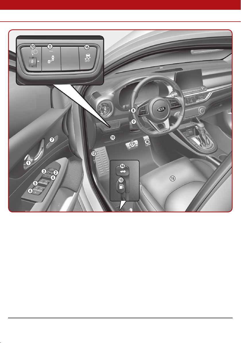
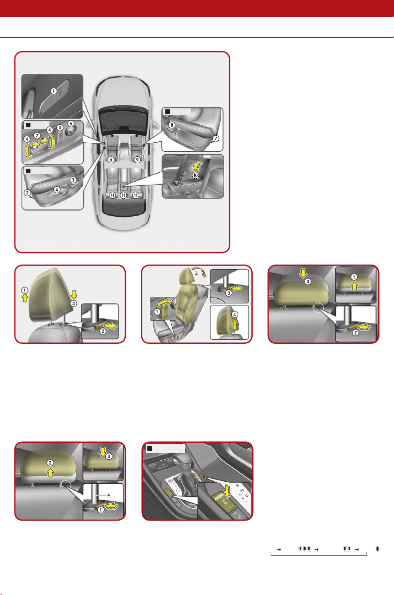
Lighting control [4]
1 OFF position
2 Auto light position*
3 Parking light position
4 Headlight position
Auto light position*
When the light switch is in
the AUTO light position, the
taillights and headlights
will be turned ON or OFF
automatically depending on
the amount of light outside
the vehicle.
Tilt & telescopic steering [4]
To change the steering wheel
angle, pull down the lock release
lever (1), adjust the steering
wheel to the desired angle (2) and
height (3), then pull up the lock-
release lever to lock the steering
wheel in place. Be sure to adjust
the steering wheel to the desired
position before driving.
To decrease the cruising speed:
Follow either of these procedures:
• Move down the SET- switch and hold it. Your vehicle set
speed will decrease by 10 km/h (5 mph). Release the lever at
the speed you want to maintain.
• Move down the SET- switch and release it immediately.The
cruising speed will decrease by 1.0 km/h (1.0 mph) each time
you move down the SET- switch in this manner.
*: if equipped
Type A
Type B To set cruise control speed:
1. Press the driving assist
(CRUISE/ ) button on the
steering wheel, to turn
the function on. The cruise
status on the LCD screen
will appear.
2. Accelerate to the desired
speed, which must be more
than 30 km/h (20 mph).
3. Move down the SET-
switch, and release it at the
desired speed. The cruise
status on the LCD screen
will appear. Release the
accelerator pedal at the
same time. The desired
speed will automatically be
maintained.
To increase cruise control set
speed:
Follow either of these
procedures:
• Move up the RES+ switch
and hold it. Your vehicle set
speed will increase by 10
km/h (5 mph). Release the
lever at the speed you want.
• Move up the RES+ switch
and release it immediately.
The cruising speed will
increase by 1.0 km/h (1.0
mph) each time you move
up the RES+ switch in this
manner.
Cruise control switch [6]
CANCEL / O: Cancels cruise
control operation.
CRUISE / : Turns cruise
control on or off.
RES+: Resumes or increases
cruise control speed.
SET-: Sets or decreases cruise
control speed.

Features of your vehicle
Warning and Indicator Lights
Symbol Color Name of the Symbol
Red Air bag warning light
Red Seat belt warning light
WK-23
Red Parking brake & brake fluid warning light
Yellow Anti-lock brake system (ABS) warning light
WK-23
Yellow/Red Electronic brake force distribution (EBD) system
warning light
Red Electronic power steering (EPS) warning light
Yellow Malfunction indicator lamp (MIL)
Red Charging system warning light
Red Engine oil pressure warning light
Yellow Engine oil level warning light*
Yellow Low fuel level warning light
Yellow Low tire pressure warning light
Red Fuel filter warning light (Diesel engine)
Yellow Master warning light
Yellow Exhaust system (DPF) warning light (Diesel engine)
Exhaust system (GPF) warning light (Gasoline engine)
Yellow SCR warning light (Diesel engine)
Yellow Overspeed warning light*
Yellow LED headlamp warning light*
Red Door ajar warning light*
Yellow Trunk/tailgate open warning light*
*: if equipped

Features of your vehicle
Warning and Indicator Lights
Please refer to the Owner’s Manual Chapter 4 for further information on Warning and Indicators Lights.
Symbol Color Name of the Symbol
Yellow Washer fluid warning light*
White Hood open warning light*
White Sunroof open warning light*
White Ice warning light*
Yellow Electronic stability control (ESC) indicator light
Yellow Electronic stability control (ESC) OFF indicator light
Yellow/Green Auto stop indicator*
Yellow Immobilizer indicator light (Without smart key)
Immobilizer indicator light (With smart key)
Green Turn signal indicator light
Green Low beam indicator light*
Blue High beam indicator light
Green Light ON indicator light
Green Front fog indicator light*
Yellow Rear fog indicator light*
Yellow Glow indicator light (Diesel engine)
Green ECO mode indicator light*
Yellow SPORT mode indicator light*
Green/White/
Yellow SMART mode indicator*
Green Cruise indicator light*
Red KEY OUT indicator light*
*: if equipped

What to do in an emergency
Towing / Changing Tires
Please refer to the Owner’s Manual Chapter 4 for further information on Warning and Indicators Lights.
When being towed by a
commercial tow truck and
wheel dollies are not used,
the front of the vehicle should
always be lifted, not the rear.
Emergency towing [7]
If towing is necessary, we
recommend you to have it
done by an authorized Kia
dealer or a commercial tow
truck service.
When towing your vehicle in an
emergency without wheel
dollies:
1. Set the ignition switch in
the ACC position.
2. Place the transaxle shift
lever in N (Neutral).
3. Release the parking brake.
Changing tires [7]
1. Park on a level surface and
apply the parking brake
firmly.
2. Shift the shift lever into
R (Reverse) with manual
transaxle.
3. Activate the hazard
warning flasher.
4. Remove the wheel lug nut
wrench, jack, jack handle,
and spare tire from the
vehicle.
5. Block both the front and
rear of wheel that is
diagonally opposite the jack
position.
6. Loosen the wheel lug nuts
counterclockwise one turn
each, but do not remove
any nut until the tire has
been raised off the ground.
9. Loosen the wheel nuts and
remove them with your
fingers. Slide the wheel off
the studs and lay it flat so
it cannot roll away. To put
the wheel on the hub, pick
up the spare tire, line up the
holes with the studs and
slide the wheel onto them. If
this is difficult, tip the wheel
slightly and get the top hole
in the wheel lined up with
the top stud. Then jiggle the
wheel back and forth until
the wheel can be slid over
the other studs.
10. To reinstall the wheel, hold
it on the studs, put the
wheel nuts on the studs
and tighten them finger
tight. Jiggle the tire to be
sure it is completely seated,
then tighten the nuts as
much as possible with your
fingers again.
11. Lower the vehicle to
the ground by turning
the wheel nut wrench
counterclockwise.
7. Place the jack at the front
(1) or rear (2) jacking
position closest to the tire
you are changing. Place
the jack at the designated
locations under the frame.
The jacking positions are
plates welded to the frame
with two tabs and a raised
dot to index with the jack.
8. Insert the jack handle
into the jack and turn
it clockwise, raising the
vehicle until the tire
just clears the ground.
This measurement is
approximately 30 mm
(1.2 in). Before removing
the wheel lug nuts, make
sure the vehicle is stable
and that there is no chance
for movement or slippage.

Smart key
What to do in an emergency
In Case of Remote Key Failure / Fuel Filler Door
Starting the engine [6]
• If the battery is weak or
the smart key does not
work correctly, you can start
the engine by pressing the
engine start/stop button
with the smart key.
• When the stop lamp fuse is
blown, you cannot start the
engine normally.
• Replace the fuse with a new
one. If it is not possible,
you can start the engine by
pressing the engine start/
stop button for 10 seconds
while it is in the ACC position.
• The engine can start without
depressing the brake pedal.
But for your safety always
depress the brake pedal and
clutch pedal (if equipped)
before starting the engine.
Mechanical key [4]
• To remove the mechanical
key, press and hold the
release button and remove
the mechanical key.
• To reinstall the mechanical
key, put the key into the hole
and push it until a click sound
is heard.
Opening the fuel filler door [4]
1. Stop the engine.
2. To open the fuel filler
door, pull up the fuel filler
door opener.
3. Pull open the fuel filler
door (1).
4. To remove the cap, turn
the fuel filler cap (2)
counterclockwise.
5. Refuel as needed.
Closing the fuel filler door [4]
1. To install the cap, turn it
clockwise until it “clicks”.
This indicates that the cap
is securely tightened.
2. Close the fuel filler door and
push it lightly and make
sure that it is securely
closed.
4 Door 4 Door

(Gasoline engine) 1.6 MPI (Gasoline engine) 1.6 MPI
(Gasoline engine) 1.6 MPI /
(Gasoline engine) 2.0 MPI
Maintenance
Copyright © 2020 Kia MOTORS Corp. All rights reserved.
MA7Q-EG0DA
Maintenance
Checking the engine oil level [8]
1. Be sure the vehicle is on
level ground.
2. Start the engine and allow
it to reach normal operating
temperature.
3. Turn the engine off and wait
for a few minutes (about
10 minutes) for the oil to
return to the oil pan.
4. Pull the dipstick out, wipe it
clean, and re-insert it fully.
5. Pull the dipstick out again
and check the level. The level
should be between F (Full)
and L (Low).
Do not overfill.
• Use a funnel to help prevent
oil from being spilled on
engine components.
• Use only the specified engine
oil. [9]
Checking the washer fluid
level [8]
• Check the fluid level and add
fluid if necessary.
• Plain water may be used if
washer fluid is not available.
However, use washer
solvent with antifreeze
characteristics in cold
climates to prevent freezing.
Checking the engine coolant
level [8]
• Check the condition and
connections of all cooling
system hoses and heater
hoses. Replace any swollen
or deteriorated hoses.
• The coolant level should be
filled between MAX and MIN
(F and L) marks on the side
of the coolant reservoir when
the engine is cool.
• If the coolant level is low, add
enough distilled (deionized) or
soft water. Bring the level to
MAX (F), but do not overfill.
• When adding coolant, use
only deionized water or soft
water for your vehicle and
never mix hard water in the
coolant filled at the factory.
• The engine in your vehicle
has aluminum engine parts
and must be protected by
an ethylene-glycol with
phosphate based coolant
to prevent corrosion and
freezing.
• DO NOT USE alcohol or
methanol coolant or mix them
with the specified coolant.
• Do not use a solution that
contains more than 60 %
antifreeze or less than 35 %
antifreeze, which would
reduce the effectiveness of
the solution.
• If frequent additions are
required, have the system
inspected by a professional
workshop. Kia recommends
to visit an authorized Kia
dealer/service partner.
For full details and instructions on any item contained in this quick reference guide,
please read the Owner’s Manual.
Other manuals for Cerato
3
This manual suits for next models
1
Table of contents
Other Kia Automobile manuals