Kia VISTO User manual


1
GENERAL INFORMATION
GENERAL
EATC0100
HOW TO USE THIS MANUAL
This manual is divided into 21 sections. The first page of each section is marked with a black tab at the edge of the
page. You can quickly find the first page of each section without looking through the whole table of contents.
Each section includes the essential removal, installation, adjustment and maintenance procedures for servicing all
body styles. This information is correct at the time of publication.
An INDEX is provided on the first page of each section to guide you to the appropriate item.
TROUBLESHOOTING tables are included for each system to help you diagnose the system problem and find the
cause. The repair for each possible cause is referred to in the remedy column to lead you to the solution quickly.
DEFINITION OF TERMS
Standard Value (Service standard)
Indicates the value used when a part or assembled item should be inspected, or the value to which a part or
assembled item should be adjusted after reinstallation. It is given by a tolerance.
Service Limit
Indicates the maximum or minimum value that a part or assembled item must meet when inspected. It is a value
established beyond the standard value.
NOTE, WARNING , CAUTION, ABBREVIATION
NOTE
Information needed in reference to a repair service.
CAUTION
Information about an activit
y
that could cause dama
g
e to the vehicle.
WARNING
Information about an activity that could cause injury or damage to the driver, occupants or
repairman.
ABBREVIATIONS
SOHC : Single Over Head Camshaft
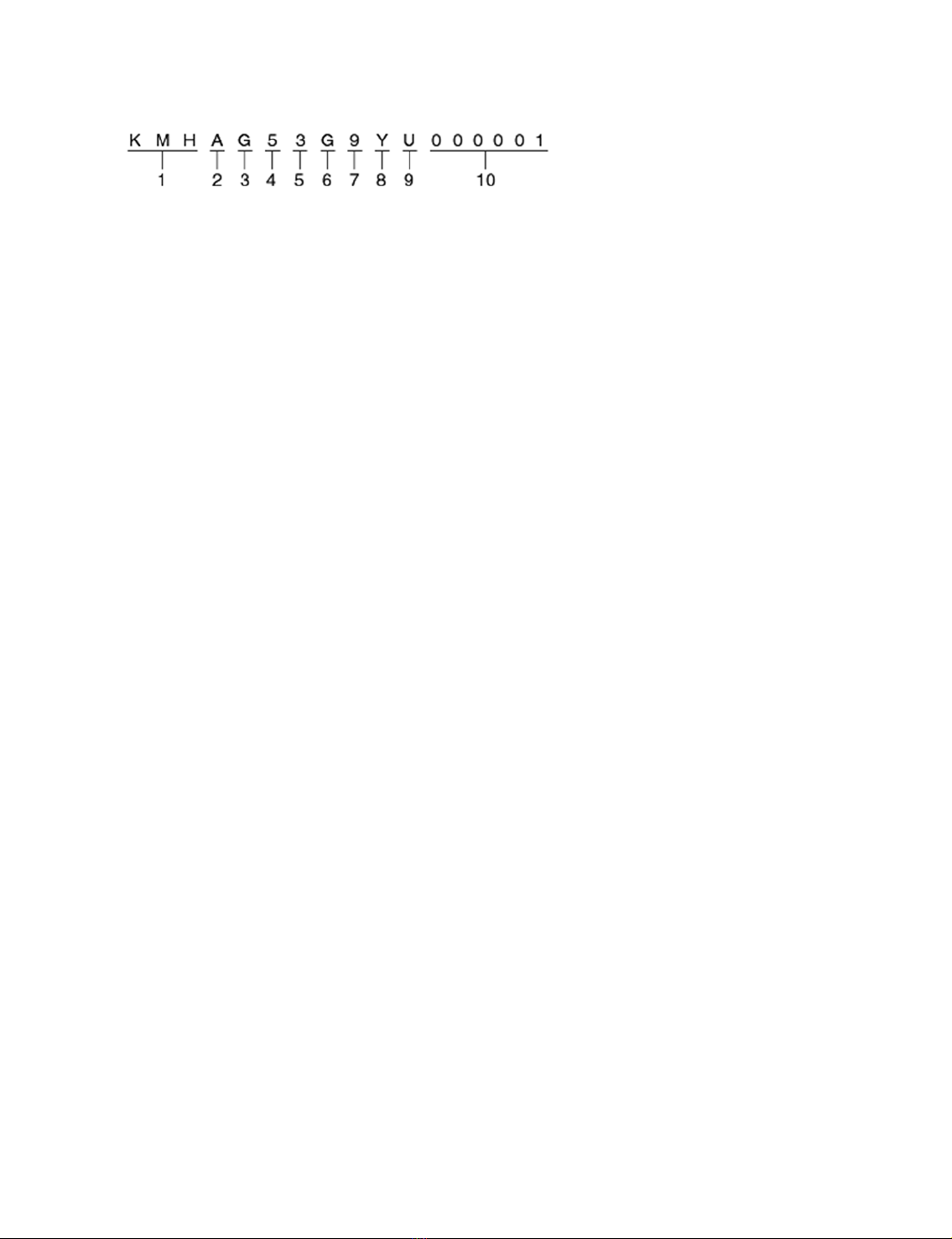
VEHICLE IDENTIFICATION NUMBER LOCATION
The vehicle identification number (VIN) is located on the top of the fire wall.

2
VEHICLE IDENTIFICATION NUMBER
The vehicle identification number consists of 17 digits.
1. W.I.C. (World manufacturer's Identification Code)
KMH - Hyundai Motor Company, Korea
2. Vehicle Line
A : ATOS
3. Model & Series
F : Standard (L)
G : Deluxe (GL)
H : Super deluxe (GLS)
4. Body Type
5 : Sedan 5DR
5. Restraint system
0 - Both sides (None)
1 - Both sides (A/Belt)
2 - Both sides (P/Belt)
3 - Driver side : A/ Belt + A/Bag, Passenger side : P/Belt
4 - A/ Belt + A/ Bag (Driver side + Passenger side)
5 - Depowered A/Bag
NOTE
A/Belt : Active belt
P/Belt : Passive belt
A/Bag : Air bag
6. Engine type
G : G 1.0 S
7. Check digit or others
P : LHD (Left Hand Driver)
R : RHD (Right Hand Driver0
8. Production year
Y - 2000 Model Year, 2 - 2002 Model Year
1 - 2001 Model Year, 3 - 2003 Model Year
9. Production plant
U - Ulsan (Korea)
10. Vehicle production sequence number
000001 - 999999

3
ENGINE IDENTIFICATION NUMBER LOCATION
The engine identification number is stamped on the right front side of the top edge of the cylinder block.
DESCRIPTION OF ENGINE IDENTIFICATION NUMBER
The engine identification number consists of 11 digits.
1. Engine fuel
G - Gasoline
2. Engine range
4 - In line 4 cycle 4 cylinder
3. Engine development order
H : Epsilon engine
4. Engine capacity
C : 999cc
5. Production year
X - 1999
Y - 2000
1 - 2001
2 - 2002
6. Engine production sequence number
000001 - 999999
PROTECTION OF THE VEHICLE
Always be sure to cover fenders, seats, and floor areas before starting work.

4
CAUTION
The support rod must be inserted into the hole near the edge of the hood whenever you inspect the
engine compartment to prevent the hood from falling and causing passible injury.
Make sure that the support rod has been released prior to closing the hood. Always check to be sure
the hood is firmly latched before driving the vehicle.
A WORD ABOUT SAFETY
The following precautions must be followed when jacking up the vehicle.
1. Block the wheels.
2. Place a jack under the specified jacking point.
3. Support the vehicle with safety stands (jack stands) Refer to the page GI-10.
4. Start the engine when engine compartment is clear.
PREPARATION OF TOOLS AND MEASURING EQUIPMENT
Be sure that all necessary tools and measuring equipment are available before starting work.
SPECIAL TOOLS
Use special tools when they are required.
REMOVAL OF PARTS
First find the cause of the problem and then determine whether removal or disassembly is required before starting
the job.
DISASSEMBLY
If the disassembly procedure is complex, requiring many parts to be disassembled, all parts should be disassembled
in a way that will not affect their performance or external appearance.

5
1. Inspection of parts
Each part, when removed, should be carefully inspected for malfunction, deformation, damage, and other
problems.
2. Arrangement of parts
All disassembled parts should be carefully arranged for effective reassembly.
Be sure to separate and correctly identify the parts to be replaced from those that will be used again.
3. Cleaning parts for reuse
All parts to be used again should be carefully and thoroughly cleaned by an appropriate method.
PARTS
When replacing parts, use HYUNDAI genuine parts.

6
REPLACEMENT
Standard values, such as torques and certain adjustments, must be strictly observed in the reassembly of all parts.
If removed, the following parts should always be replaced with new ones.
1. Oil seals
2. Gaskets
3. O-rings
4. Lock washers
5. Cotter pins (split pins)
6. Plastic nuts
Depending on their location.
1. Sealant should be applied to gaskets.
2. Oil should be applied to the moving components of parts.
3. Specified oil or grease should be applied to the prescribed locations (oil seals, etc.) before assembly.

7
ADJUSTMENT
Use gauges and testers to adjust correctly the parts to standard values correctly.
ELECTRICAL SYSTEM
1. Be sure to disconnect the battery cable from the negative (-) terminal of the battery.
2. Never pull on the wires when disconnecting connectors.
3. Locking connectors will click when the connector is secure.
4. Handle sensors and relays carefully. Be careful not to drop them or hit them against other parts.
RUBBER PARTS AND TUBES
Always prevent gasoline or oil from touching rubber parts or tubing.

8
MEASURING BODY DIMENSIONS
1. Basically, all measurements in this manual are taken with a tracking gauge.
2. When a measuring tape is used, check to be sure there is no elongation, twisting or bending
3. For measuring dimensions, both projected dimensions and actual-measurement dimensions are used in this
manual.
DIMENSIONS PROJECTED
1. These are the dimensions measured when the measurement points are projected from the vehicle's surface,
and are the reference dimensions used for body alterations.
2. If the length of the tracking gauge probes is adjustable, measure it by lengthening one of two probes as long
as the different value in height of the two surfaces.
MEASURING ACTUAL DIMENSIONS
1. These dimensions indicate the actual linear distance between measurement points, and are used as the
reference dimensions when a tracking gauge is used for measurement.
2. First adjust both probes to the same length (A=A') before measurement.
NOTE
Check the probes and
g
au
g
e itself to make sure there is no free pla
y
.

9
MEASUREMENT POINT
Measurements should be taken at the center of the hole.
CHECKING CABLES AND WIRES
1. Check the terminal for tightness.
2. Check terminals and wires for corrosion from battery electrolyte, etc.
3. Check terminals and wires for open circuits.
4. Check wire insulation and coating for damage, cracks and degrading.
5. Check the conductive parts of terminals for contact with other metallic parts (vehicle body and other parts).
6. Check grounded parts to verify that there is complete continuity between their attaching bolt(s) and the
vehicle's body.
7. Check for incorrect wiring.
8. Check that the wiring is so clamped to prevent contact with sharp corners of the vehicle body, etc. or hot
parts (exhaust manifold, etc.)
9. Check that the wiring is clamped firmly to provide enough clearance from the fan pulley, fan belt and other
rotating or moving parts.
10. Check that the wiring has a little space so that it can vibrate between fixed and moving parts such as the
vehicle body and the engine.
CHECKING FUSES
A blade type fuse has test taps provided to allow checking the fuse itself without removing it from the fuse block.
The fuse is good if the test lamp lights up when one lead is connected to the test taps (one at a time) and the other
lead is grounded. (Turn the ignition switch so that the fuse circuit becomes operative.)

10
SERVICING THE ELECTRICAL SYSTEM
1. Prior to servicing the electrical system, be sure to turn off the ignition switch and disconnect the battery
ground cable.
NOTE
In the course of MFI or ELC system diagnosis, when the battery cable is removed, any
diagnostic trouble code retained by the computer will be cleared. Therefore, if necessar
y
, read
the diagnostic codes before removing the battery cable.
2.
3. Attach the wiring harnesses with clamps so that there is no slack. However, for any harness which passes
the engine or other vibrating parts of the vehicle, allow some slack within a range that does not allow the
engine vibrations to cause the harness to come into contact with any of the surrounding parts, and then
secure the harness by using a clamp.

11
4. If any section of a wiring harness interferes with the edge of a part, or a corner, wrap the section of the
harness with tape or something similar in order to protect it from damage.
5. When installing any parts, be careful not to pinch or damage any of the wiring harnesses.
6. Never throw relays, sensors or electrical parts, or expose them to strong shock.
7. The electronic parts used in the computer, relays, etc. are readily damaged by heat. If there is a need for
service operations that may cause the temperature to exceed 80°C (176°F ), remove the electronic parts
beforehand.

12
8. Loose connectors cause problems. Make sure that the connectors are always securely fastened.
9. When disconnecting a connector, be sure to grip only the connector, not the wires.
10. Disconnect connectors which have catches by pressing in the direction of the arrows shown the illustration.

13
11. Connect connectors which have catches by inserting the connectors until they make a clicking sound.
12. When using a circuit tester to check continuity or voltage on connector terminals, insert the test probe into
the harness side. If the connector is a sealed connector, insert the test probe through the hole in the rubber
cap until it contacts the terminal, being careful not to damage the insulation of the wires.
13. To avoid overloading the wiring, take the electrical current load of the optional equipment into
consideration, and determine the appropriate wire size.
Norminal size SAE gauge No.
Permissible current
In engine compartment Other areas
0.3 mm² AWG 22 - 5A
0.5 mm² AWG20 7A 13A
0.85 mm² AWG18 9A 17A
1.25 mm² AWG16 12A 22A
2.0 mm² AWG14 16A 30A
3.0 mm² AWG12 21A 40A
5.0 mm² AWG10 31A 54A

14
PRECAUTIONS FOR CATALYTIC CONVERTER
CAUTION
If a large amount of unburned gasoline flows into the converter, it may overheat and create a fire
hazard. To prevent this, observe the following precautions and explain them to your customer.
1. Use only unleaded gasoline.
2. Do not run the engine while the car is at rest for a long time. Avoid running the engine at fast idle for more
than 10 minutes and at idle speed for more than 20 minutes.
3. Avoid spark-jump tests. Do spark-jumps only when absolutely necessary. Perform this test as rapidly as
possible and, while testing, never race the engine.
4. Do not measure engine compression for an extended time. Engine compression tests must be made as
rapidly as possible.
5. Do not run the engine when the fuel tank is nearly empty. This may cause the engine to misfire and create
an extra load on the converter.
6. Avoid coasting with the ignition turned off and during prolonged braking.
7. Do not dispose of a used catalytic converter together with parts contaminated with gasoline or oil.
SRS SYSTEM COMPONENTS INFORMATION
CUSTOMER CAUTIONS
Failure to carry out service operations in the correct sequence could cause the airbag system to be deployed
unexpectedly during servicing, and a serious accident to occur. Further, if there is a mistake in servicing the airbag
system, it is possible that the airbag may fail to operate when required. Before servicing (including removal or
installation of parts, inspection or replacement), be sure to read the following items carefully, then follow the correct
procedures described in the repair manual.
1. Work must be started approx. 30 seconds or longer after the ignition switch is turned to the LOCK position
and the negative (-) battery cable is disconnected. (The airbag system is equipped with a back-up power
source. If work is started within 30 seconds when disconnecting the negative (-) battery cable of the battery,
the airbag may be operative.) When the negative (-) terminal cable is disconnected from the battery, the
clock and audio systems memories will be erased. Before starting work, record the setting of the audio
memory system. When work is finished, reset the audio system as before and adjust the clock.
2. Malfunction symptoms of the airbag system are difficult to confirm, so diagnostic codes become the most
important source of information when troubleshooting. When troubleshooting the airbag system, always
read the diagnostic trouble codes before disconnecting the battery.
3. Never use airbag parts from another vehicle. When replacing parts, replace them with new parts.
4. Never attempt to disassemble and repair the airbag modules, SRSCM, clock spring and Air-bag wiring
harness in order to reuse it.
5. If the SRSCM or air-bag module have been dropped, or if there are cracks, dents or other defects in the
case, bracket or connector, replace them with new ones.
6. After work on the airbag system is completed, reset the SRS SRI.

15
CAUTION
1. Never use a jack beneath the lateral rod or rear suspension assembly.
2. In order to prevent scarring the sub frame, place a piece of cloth on the jack's contact surface
(to prevent corrosion caused by damage to the coating).
3. Never support a vehicle with only a jack. Always use safety stands.
4. Do not attempt to raise one entire side of the vehicle by placing a jack midway between the
front and rear wheels. To do so could result in permanent damage to the body.

16
TIGHTENING
TORQUE TABLE OF
STANDARD PARTS
Bolt nominal diameter
(mm)
Pitch (mm)
Torque Nm (kg.cm, Ib.ft)
Head Mark 4 Head Mark 7
M5 0.8 3-4 (30-40, 2.2-2.9) 5-6 (50-60, 3.6-4.3)
M6 1.0 5-6 (50-60, 3.6-4.3) 9-11 (90-110, 6.5-8.0)
M8 1.25 12-15 (120-150, 9-11) 20-25 (200-250, 14.5-18.0)
M10 1.25 25-30 (250-300, 18-22) 30-50 (300-500, 22-36)
M12 1.25 35-45 (350-450, 25-33) 60-80 (600-800, 43-58)
M14 1.5 75-85(750-850,54-61) 120-140(1,200-1,400,85-100)
M16 1.5 110-130(1,100-1,300,80-94) 180-210(1,800-2,100, 130-150)
M18 1.5 160-180(1,600-1,800, 116-130) 260-300(2,600-3,000, 190-215)
M20 1.5 220-250 (2,200-2,500, 160-
180) 360-420 (3,600-4,200,260-300)
M22 1.5 290-330 (2,900-3,300, 210-
240) 480-550 (4,800-5,500,350-400)
M24 1.5 360-420 (3,600-4,200, 260-
300) 610-700 (6,100-7,000, 440-505)
NOTE
1. The torques shown in the table are standard values under the following conditions:
oNuts and bolts are made of galvanized steel bar.
oGalvanized plain steel washers are inserted.
oAll nuts, bolts, and plain washers are dry.
2. The torques shown in the table are not applicable:
oWhen spring washers, toothed washers and the like are inserted.
oIf plastic parts are fastened.
oIf self-tapping screws or self-locking nuts are used.
oIf threads and surfaces are coated with oil.
3. If you reduce the torques in the table to the percentage indicated below, under the following
conditions, if will be the standard value.
oIf spring washers are used. : 85%
oIf threads and bearing surfaces are stained with oil. : 85%

17
Recommended Lubricants
RECOMMENDED LUBRICANTS EATC0200
Parts Specifications Remarks
Engine oil API Classification SE Above For further details, refer to SAE
viscosity number
Manual transaxle API classification GL-4 SAE grade number:
SAE 75W/90
Automatic transaxle GENUINE HYUNDAI transaxle oil,
GENUINE DIAMOND ATF SP-II
M
Brake DOT 3 or DOT 4
Cooling system High quality ethylene glycol Concentration level 40% (tropical)
Concentration level 50% (normal)
Power steering PSF-3
Transaxle linkage, parking brake
cable mechanism, hood lock and
hook, door latch, seat adjuster, trunk
latch, door hinges, trunk hinges
Multipurpose grease NLGI grade #2
M/EAST : Middle East, GEN.: General Areas
AUST.: Australia, EC : European Communities
LUBRICANTS
CAPACITIES
liter (U.S. qts., lmp.qts.)
Description
Capacities
1.0 I4
Engine oil
Oil pan 2.5 (2.64, 2.20)
Oil filter 0.3 (0.32, 0.26)
Total 2.8 (2.96, 2.46)
Cooling system 6.0 (6.34, 5.28)
Manual transaxle 2.15 (2.27, 1.89)
Automatic transaxle 4.0 (4.23, 2.52)
Power steering 0.9 (0.95, 0.79)

18
Maintenance Information
MAINTENANCE EATC0300
CHANGING ENGINE OIL
1. If the engine is cold, run the engine until it reaches normal operating temperature.
2. Turn off the engine.
3. Remove the oil filler cap and drain plug. Drain the engine oil.
4. Tighten the drain plug to the specified torque.
Tightening torque
Oil pan drain plug :
35-45 N.m (350-450 kg.cm, 25-33 lb.ft)
NOTE
Whenever ti
g
htenin
g
the oil drain plu
g
, use a new drain plu
g
g
asket.
5. Fill new engine oil through the oil filler cap opening.
NOTE
Do not overfill, this will cause oil aeration and loss of oil pressure.
6. Install the oil filler cap.
7. Start and run the engine.
8. Turn off the engine and then check the oil level. Add oil if necessary.

19
REPLACING THE ENGINE OIL FILTER
1. Use a filter wrench to remove the oil filter.
2. Before installing a new oil filter on the engine, apply clean engine oil to the surface of the rubber gasket.
3. Tighten the oil filter to the specified torque.
Tightening torque
Oil filter : 12 -16 N.m (120-160 kg.cm, 9-12 lb.ft)
4. Start and run the engine and check for engine oil leaks.
5. After turning off the engine, check the oil level and add oil as necessary.
REPLACING THE AIR CLEANER FILTER
The air cleaner filter will become dirty during use and the filtering efficiency will be substantially reduced. Replace
with a new one as needed.
1. Disconnect the clip holding air cleaner filter cover.
2. Remove the air filter cover.
3. Remove the air cleaner filter.
4. Install a new air cleaner filter and replace the air cleaner filter cover.
Table of contents
Other Kia Automobile manuals

Kia
Kia Sedona 2010 User manual

Kia
Kia Forte 2014 Owner's manual

Kia
Kia CADENZA 2019 Parts list manual

Kia
Kia Telluride 2023 User manual

Kia
Kia Soul 2023 User manual

Kia
Kia Optima User manual

Kia
Kia Sedona User manual

Kia
Kia Venga User manual

Kia
Kia EV6 2024 Assembly instructions

Kia
Kia Borrego 2011 User manual

Kia
Kia 2016 Sportage User manual

Kia
Kia Sorento 2022 User manual

Kia
Kia Optima User manual

Kia
Kia niro 2023 User manual

Kia
Kia K900 2017 Assembly instructions

Kia
Kia Rio 2022 User manual

Kia
Kia 2016 Sedona User manual

Kia
Kia K2700 2022 User manual

Kia
Kia Optima PHEV 2018 User manual

Kia
Kia Magentis User manual