10
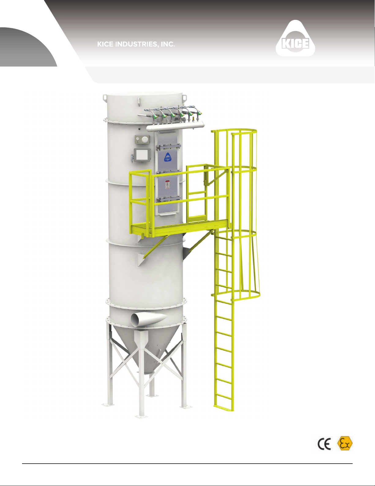
Kice Industries, Inc. 012420 / FLT-M02-0004
S P
•
29CFR1910.147, local enforcement authorities, OSHA, and facility safety practices, before removing any protective
cover, guard, grate or maintenance gate.
•
you have been thoroughly trained in its use by your employer.
•
Experienced employees should receive refresher training for potential hazards and up to date training records should
be maintained at the job site.
• Assume at all times that power is “on”. Treat all conditions as live. This practice ensures a cautious approach that may
prevent an accident or injury.
• Before applying power to any equipment, make certain that all personnel are clear of the machine.
• Operate safely at all times. Use personal protective equipment when and where appropriate, such as hard hats,
personal protective equipment in good repair and convenient to the operator.
•
and fall arresters must be worn by personnel.
•
after all pipes and hoses, including upstream and downstream components, have been completely connected to the
piping system. This will prevent human access while the machine is running.
•
maintenance panels are in place and securely fastened.
• All protective covers, guards, grates, maintenance panels, switches and warning decals must be kept in place and in
good repair. Any equipment with a damaged malfunctioning, defective, or missing protective device must be taken out
of service until the protective device can be repaired or replaced.
•
it is in need of service, lubrication, maintenance or repair.
•
•
device must be installed to achieve this.
• The compressed air supply must be disconnected from the system before service and repair work is carried out. The
company (operator) of the overall system.
•
•
WARNING: All owners and operators should read this manual and be instructed in safe
operating and maintenance procedures before attempting to uncrate, install, operate, adjust
or service this equipment.