For warranty information please visit: kichler.com/customer-care/warranty-information/landscape-warranty
Pour de plus amples informations sur la garantie, cliquez sur le lien ci-dessous : kichler.com/customer-care/warranty-information/landscape-warranty
IS-16097-CB
We’re here to help 866-558-5706
Hrs: M-F 9am to 5pm EST
OUTDOOR USE ONLY
DOM ETRE INSTALLE A L’EXTERIEUR
For Assembling and Installing Fixtures in Canada
Pour L’assemblage et L’installation Au Canada
Nous sommes là pour vous aider 866-558-5706
Heures : du lundi au vendredi, de 9h à 17h (heure de l’Est)
START
DÉMARRAGE
Fig. 5
Fig. 1
SAFETY INSTRUCTIONS
READ THIS FIRST
KEEP THESE INSTRUCTIONS
CAUTION – RISK OF SHOCK –
Disconnect Power at the main circuit breaker panel or main fusebox before
starting and during the installation.
This xture is intended for installation in accordance with the National
Electric Code (NEC) and Local code specications. Failure to adhere to these
codes and instructions may result in serious injury and/or property damage
and will void the warranty. If you are not familiar with code requirements,
installation by a certied electrician is recommended.
Instructions for adding the Hexcell Louver Part No. 16097BK
to the In-Ground Fixtures 16023CBR27, 16023CBR30, 16024CBR27,
16024CBR30, 16025CBR27 and 16025CBR30.
This item is used in conjunction with Hexcell Louver Part No. 16075BK.
INSTALLATION
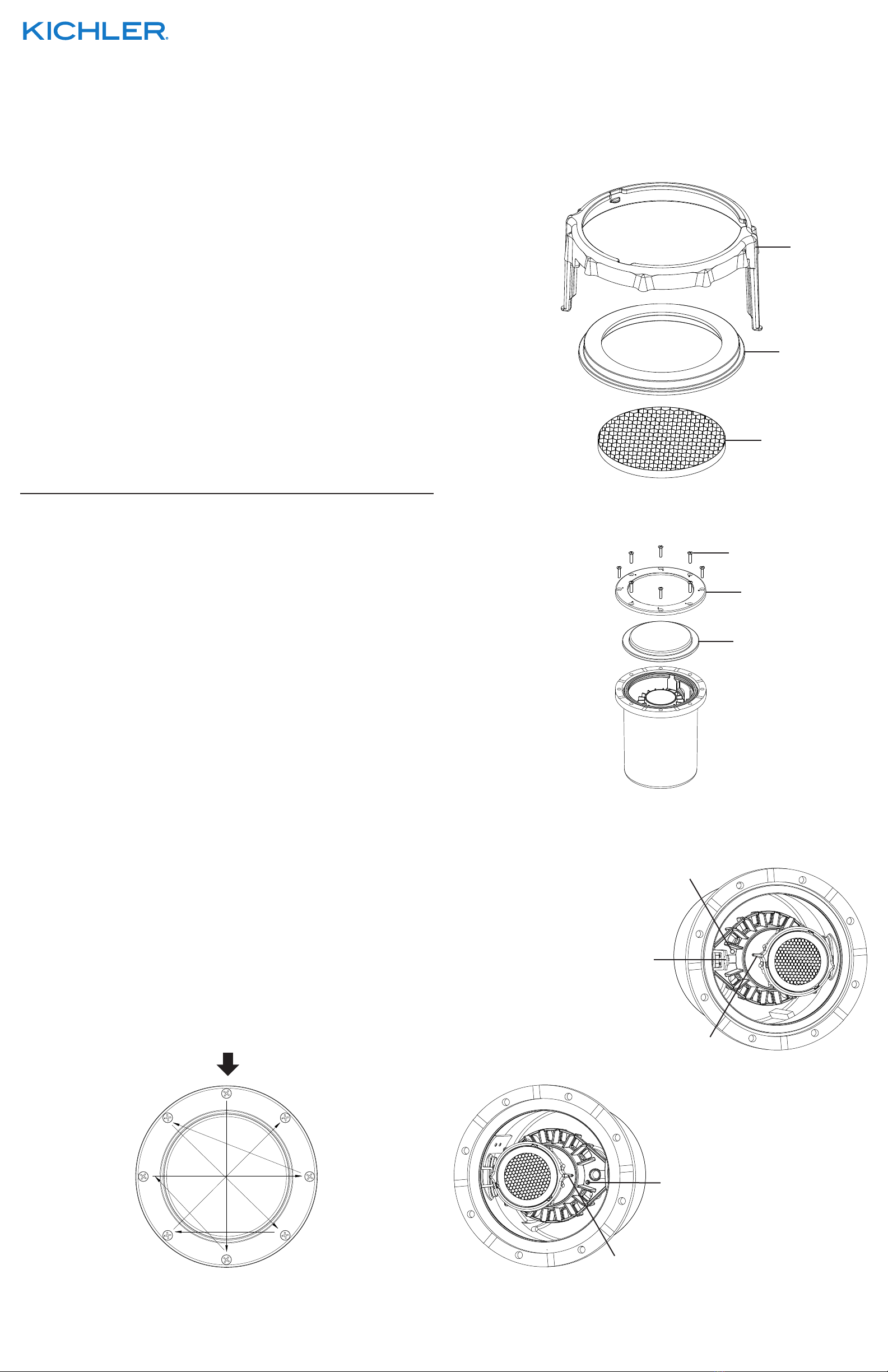
1) First assemble Hexcell Louver to retaining ring and then snap the retaining ring
with Hexcell Louver into the lens holder (see Fig. 1).
2) Remove 8 screws, trim ring and glass cover, place hardware in a secure place
(see Fig. 2).
3) First, insert leg of lens holder in mounting hole on light module closest to
programing sensor, press down until leg locks in place (see Fig. 3). Secondly,
pivot lens holder so that the other leg lines up with the other mounting hole.
Flex other leg into hole and press down until leg locks in place (see Fig. 4).
4) Once Hexcell Louver is installed, reassemble glass cover and trim ring using
the 8 screws (see Fig. 2).
5) To ensure proper sealing of unit, replace all 8 screws and hand tighten screws
to where the screw begins to engage with the housing.
6) Once all screws are in place, use the numbers on the trim ring and torque each
screw following the torqueing sequence. Tighten each screw in pattern 20-25
in-lbs (2.3-2.8 N-m) (see Fig. 5).
CONSIGNES DE SÉCURITÉ
À LIRE EN PREMIER
CONSERVER CES CONSIGNES
ATTENTION – RISQUE DE DÉCHARGES ÉLECTRIQUES –
Couper le courant au niveau du panneau du disjoncteur du circuit principal
ou de la boîte à fusibles principale avant de procéder à l’installation.
Cet appareil est prévu pour l’installation conformément au Code électrique
National (NEC) et les spécications du code Local. Ne pas respecter ces
codes et instructions peut entraîner des blessures graves et/ou des
dommages matériels et annulera la garantie. Si vous ne connaissez pas les
exigences de ces codes, il est recommandé de coner l’installation à un
électricien certié.
Instructions sur l’ajout de la grille Hexcell réf. 16097BK aux luminaires enterrés
dans le sol 16023CBR27, 16023CBR30, 16024CBR27, 16024CBR30,
16025CBR27 et 16025CBR30.
Cet article est utilisé conjointement avec la grille Hexcell réf. 16075BK.
INSTALLATION
1) Assemblez d’abord la grille Hexcell sur la bague de retenue, et enclenchez
ensuite cette bague avec la grille Hexcell dans le support de lentille
(voir Fig. 1).
2) Retirez les huit (8) vis, l’anneau de garniture et le couvercle en verre, placez le
matériel dans un endroit sûr (voir Fig. 2).
3) Commencez d’abord par insérer le pied du support de lentille dans le trou de
montage du module d’éclairage le plus proche du capteur de programmation,
et appuyez ensuite jusqu’à ce que le pied se verrouille en place (voir Fig. 3).
Faites maintenant pivoter le support de lentille de sorte que l’autre pied soit
aligné avec l’autre trou de montage. Insérez l’autre pied dans le trou et
appuyez jusqu’à ce que le pied soit bien en place (voir Fig. 4).
4) Une fois que la grille Hexcell est installée, réassemblez le couvercle en verre et
l’anneau de garniture à l’aide des huit (8) vis (voir Fig. 2).
5) Pour garantir une bonne étanchéité, replacez les huit (8) vis et serrez-les à la
main au point où la vis commence à s’engager dans le boîtier.
6) Unefoisquetouteslesvissontenplace,utilisezleschiressurl’anneaude
garniture et serrez chaque vis en suivant la séquence de serrage. Serrez les
vis comme suit 20-25 po-lb (2,3-2,8 N-m) (voir Fig. 5).
1
8
4
6
2
7
3
5
Fig. 3
Fig. 4
Fig. 2
LENS HOLDER
SUPPORT DE
LENTILLE
RETAINING RING
BAGUE DE
RETENUE
HEXCELL LOUVER
GRILLE HEXCELL
SCREWS
VIS
TRIM RING
ANNEAU DE GARNITURE
GLASS COVER
COUVERCLE EN VERRE
MOUNTING HOLE ON LIGHT MODULE
TROU DE MONTAGE DU MODULE
D’ÉCLAIRAGE
PROGRAMMING SENSOR
CAPTEUR DE
PROGRAMMATION
LENS HOLDER LEG
PIED DU SUPPORT DE
LENTILLE
LENS HOLDER LEG
PIED DU SUPPORT DE
LENTILLE
MOUNTING HOLE ON LIGHT MODULE
TROU DE MONTAGE DU MODULE
D’ÉCLAIRAGE


