KICK ASS KABTRYSHUNT User manual

®
12V BATTERY
MONITOR WITH
500A SHUNT
KABTRYSHUNT
V0.8
USER MANUAL
2 5 0 0
.

TABLE OF CONTENTS
1
1
1
2
2
3
3
4
6
7
8
- - - - - - - - - - - - - - - - - - - - - - - - - - -- - - - - - - - - - - - - - - -
- - - - - - - - - - - - - - - - - - - - - - - - - - -- - - - - - - - - - - - - - - -
- - - - - - - - - - - - - - - - - - - - - - - - - - -- - - - - - - - - - - - - - - -
- - - - - - - - - - - - - - - - - - - - - - - - - - -- - - - - - - - - - - - - - - -
- - - - - - - - - - - - - - - - - - - - - - - - - - -- - - - - - - - - - - - - - - -
- - - - - - - - - - - - - - - - - - - - - - - - - - -- - - - - - - - - - - - - - - -
- - - - - - - - - - - - - - - - - - - - - - - - - - -- - - - - - - - - - - - - - - -
- - - - - - - - - - - - - - - - - - - - - - - - - - -- - - - - - - - - - - - - - - -
- - - - - - - - - - - - - - - - - - - - - - - - - - -- - - - - - - - - - - - - - - -
- - - - - - - - - - - - - - - - - - - - - - - - - - -- - - - - - - - - - - - - - - -
- - - - - - - - - - - - - - - - - - - - - - - - - - -- - - - - - - - - - - - - - - -
WHY KICKASS?WHY KICKASS?
OVERVIEWOVERVIEW
WARNINGSWARNINGS
INCLUDED PARTSINCLUDED PARTS
OPTIONAL ACCESSORIESOPTIONAL ACCESSORIES
PRODUCT OVERVIEWPRODUCT OVERVIEW
SPECIFICATIONSSPECIFICATIONS
INSTALLATIONINSTALLATION
SETUPSETUP
OPERATIONOPERATION
TROUBLESHOOTINGTROUBLESHOOTING
WHY KICKASS?
OVERVIEW
WARNINGS
INCLUDED PARTS
OPTIONAL ACCESSORIES
PRODUCT OVERVIEW
SPECIFICATIONS
INSTALLATION
SETUP
OPERATION
TROUBLESHOOTING

1
WHY KICKASS?
KickAss is focussed on bringing the luxury of home to the outdoors. Your one stop shop for 12V
products. All of our products are designed to be plug and play for the ultimate camping experience.
OVERVIEW
WARNINGS
The KickAss Battery Monitor with 500A Shunt includes the following features:
ŸBattery State of Charge (SOC %).
ŸInstantaneous current (A) flow, positive when charging, negative when discharging
ŸBattery voltage
ŸAmbient temperature
ŸRemaining time to full/empty calculations
ŸLow battery / Low SOC alarm - Audible alarm can be muted
ŸRemote Display with back lit LCD screen
ŸPlease read and understand the product user manual and warnings carefully before installing
and operating.
ŸAny 12V installation work should be done by a professional, failing to do this may result in
damage to your unit or vehicle.
ŸEnsure suitable gauge wiring is used.
ŸIt is the customers responsibility to ensure that all components are safely and correctly installed.
ŸDisassembling the device may void warranty.
ŸDo not expose the display to excessive moisture or dust.
ŸDo not expose the display screen to excessive sunlight, doing so may shorten the lifespan of the
LCD.
CONGRATULATIONS ON PURCHASING YOUR NEW
KICKASS 12V BATTERY MONITOR
WITH 500A SHUNT

2
INCLUDED PARTS
OPTIONAL ACCESSORIES
500A Shunt with M8 Bolts
Shunt Holder
B+ Wire (Shunt power and voltage sensing)
Battery Monitor Display
KA recommends using the 5M (RDU) extension cable to
remotely mount your Battery Monitor Display.
SKU: KARDUEXT5M
5m extension cable
5m Battery Temperature Sensor
Shunt Data and Power Cable Mounting Screws

3
PRODUCT OVERVIEW
SPECIFICATIONS
SOC Display with
Energy Ring
Instantaneous Current
Draw (+ or -)
Battery Voltage
Back Button
OK Button
Temperature
Time Remaining
to Full/Empty
Charge/Discharge
Battery
Up Button
Down Button
Description
Working Voltage Range
Working current (backlight on)
Standby current (backlight off)
Accuracy
Battery Capacity Range
Operating Temperature Range
Display Housing Dimensions
B+ Wire
Display Temperature Sensor Cable
Display Data Cable
Shunt Assembly Data Cable
Optional extension cable wire length
Parameter
10-30V DC
~100 mA
~1-2 mA
1%
0.1 - 999.9Ah
-10º to 60º
126L x 66.6H
20AWG, Length: 100mm
5m
500mm
500mm
Recommended 5m Extension Cable

4
INSTALLATION
Fitting Shunt Assembly
The shunt can be connected to a battery in two ways, bolted directly to the negative battery terminal
or connected via a short wire to the negative terminal.
Option 1 - Direct to Battery
1. To bolt the shunt directly to the battery terminal, remove the bolts from the shunt assembly and
discard the shunt holder.
2. Using the included M8 bolt, washers and nut, attach the shunt side labeled "B-" to the negative
battery terminal.
3. Fit the B+ Wire by inserting the exposed conductor end into the small green terminal block
located on the shunt. This is labeled B+. Tighten down the the terminal block screw with a 2.4mm
flat head screw driver.
4. Now fit the ring terminal to the battery positive pole, along with the system positive loads.
B- P-
B+ B+
B- P-
B+ B+
Option 2 - Fit shunt assembly using holder
1. The shunt can be mounted to a flat surface using any of the pre drilled holes in the shunt holder.
2. Connect a cable assembly using M8 ring terminals and a minimum of 25mmsq wire, to the shunt
side labeled "B-". The cable assembly should be maximum of 300mm long. Connect the other
side of the cable assembly to the battery Negative terminal.
3. Follow steps 3 and 4 as above.
12 VOLT - 120A/H
www.kickassproducts.com.au
AGM - DEEP CYCLE
VISIT OUR WEBSI TE FOR MOR E DETAILS
B- P-
B+ B+
(+) Loads
Shunt Mount
screw fixing points
CAUTION:
- Please check all connections are correctly terminated and secured tightly!
- Ensure the B+ Wire is fitted using circuit protection: Split conduit or an in-line fuse rated at 3A will
be suitable.
(+) Loads

5
INSTALLATION
Connecting Display to the Shunt Assembly
The Battery Monitor Display can be connected to the Shunt, with the provided cables. To do this
firstly connect the data cable to the shunt assembly by plugging in the small white 5 pin connector,
now connect the two round black connectors to join the display and shunt together. The Temperature
sensors can now be run to the battery or desired location for ambient temperature reading.
OK
%
CAP
FCV
LCA
ZCV
POV
ATT
CURRENT
VOLTAGE
TEMP
TIME REMAINING
AH
V
°C
H
B- P-
B+ B+
12 VOLT - 120A/H
www.kickassproducts.com.au
AGM - DEEP CYCLE
VISI T OUR WEB SITE FOR M ORE DETAIL S
Connecting Loads and Chargers to Shunt Assembly
When connecting loads and chargers to the battery using the Shunt, system negative connections
must be connected to the P- side of the Shunt Assembly. No negative connections should be made
directly to the battery terminal as this will cause the battery monitor to provide false readings. When
wiring batteries in parallel, ensure the correct connection configuration is used. Please refer to
diagram.
CAUTION: Use a suitably rated Fuse/Circuit breaker for all loads. When using the shunt in
theparallel configuration, we recommend using an in line fuse for the B+ Wire. See diagram.
TO ELECTRICAL
EQUIPMENT AND
CHARGING UNIT
SINGLE BATTERY
BATTERY A
PARALLEL BATTERIES
BATTERY A
TO ELECTRICAL EQUIPMENT
AND CHARGING UNIT
BATTERY B
TEMP SENSOR
FUSE
FUSE
FUSE

6
Battery Capacity (Ah)
Full Cell Voltage (V)
Low Capacity Alarm (Ah)
Zero Cell Voltage (V)
Power Off Voltage (V)
Battery Attenuation Ratio (H)
SETUP
Initial Setup
Before powering any system loads, the display must be calibrated
to 100% SOC. Do this by ensuring your battery bank is fully
charged and the display is showing 100%. To manually calibrate
the SOC, press and hold the UP arrow for 3 seconds.
NOTE: The connected battery charger should be in the float stage
before manually calibrating the display.
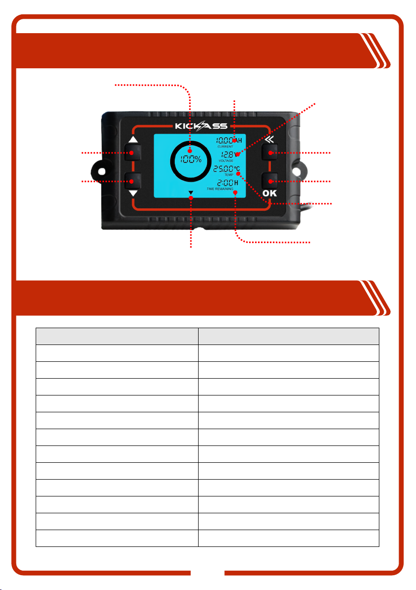
OK
CURRENT
VOLTAGE
TEMP
TIME REMAINING
AH
V
°C
H
%
100
1000
12.8
25.00
2:00
Setting Parameters
To access the parameter setting menu, press and hold the OK
button for approximately 3 seconds.
OK
CURRENT
VOLTAGE
TEMP
TIME REMAINING
AH
V
°C
H
%
100
1000
12.8
25.00
2:00
The following screen will be displayed.
The selected line will begin to flash, to
navigate through each line use the up
and down arrows. Click OK to select
the parameter and then using the up
and down arrows, set the values. Use
the OK button to move the cursor to
the left. The Back (<<) button can be
used to exit out of the selected
parameter and used again to close the
settings menu.
Each of the following parameters will need to be set, below is a table which shows typical values for
different battery types:
CAP - Battery Capacity: The total capacity of the battery bank is measured in Ah and is the total capacity
of your battery bank. For example: 2x 120AH batteries connected in parallel will total 240Ah.
FCV - Full Cell Voltage: This parameter setting is the voltage point at which the battery is fully charged.
When this voltage point is reach, the displayed SOC will calibrate to 100%. The system has now calculate
that the battery bank is fully charged. It is recommended to set this value to the max charge voltage of
your battery charger. Please check the manufactures specifications. NOTE: If calibration is off, see trouble
shooting guide for details.
LCA - Low Capacity Alarm: An audible alarm will sound when the remaining capacity is below this set
value and the current (A) value will flash on the display. For lead acid batteries like AGM, it is recommend
to set this value equal to or above the recommend usable capacity (50% of the total CAP). For example, a
120Ah AGM battery should be set to 60Ah or above.
ZCV - Zero Cell Voltage: The zero cell voltage is the value point at which the battery bank is empty. Once
this value has been reached, the SOC% will automatically reset to 0% and voltage display will flash. The
audible alarm will also sound once per 10s if the load discharge the continues.
NOTE: This value should be set just above the recommended minimum operating voltage of your battery
type. For example, Lithium: 10~10.4V, AGM: 10.5~10.9V
POV - Power Off Voltage: The power off voltage is the value point at which the display screen will turn off
to save power. This will occur after 10s once the battery voltage is below this set value. To wake the
screen up, press the OK button.
ATT - Battery Attenuation Ratio: The Battery attenuation ratio is measured as a percentage (%). This
value is the ratio at which the total (effective) capacity will reduce after each full (discharge/charge) cycle
of your battery bank. The capacity value is automatically changed according to this ratio. E.g. If a 200Ah
(effective capacity) battery has an attenuation value of 1%, the effective capacity after 1 cycle will be
198Ah, after 2 cycles it will be 196.02Ah.
CAP
FCV
LCA
ZCV
POV
ATT
CURRENT
VOLTAGE
TEMP
TIME REMAINING
AH
V
°C
H
%
100
1000
12.8
25.00
2:00

7
Recommended Values for Different Battery Types
* Rated Capacity - The capacity the battery is rated to by the manufacturer. For many battery types like AGM, it is
not recommended to use 100% of the battery capacity.
** DOD: Depth of Discharge - The percentage at which the battery is discharged in relation to the rated capacity.
eg. At 80% DOD, the State of Charge is approximately 20% of the total rated capacity of the battery.
Battery Type GEL AGM WET CALCIUM LITHIUM
CAP
*Total rated capacity of battery bank.
For example: A single @ 120Ah battery: CAP= 120Ah,
2x battery @ 120Ah: CAP= 240AH
FCV
(refer to
charger spec)
14.1V 14.4-14.7V 14.7V 14.7V 14.4-14.6V
LCA 50%-60% of CAP
ZCV 10.8V 10.5V
POV 11.5V 12V
ATT
At 80% DOD**: Rated Capacity ÷ 500
At 50% DOD**: Rated Capacity ÷ 1000
At 20% DOD**: Rated Capacity ÷ 2000
20%
Recommended Attentiation Values
80% DoD 50% DoD 20% DoD
120Ah AGM
170Ah AGM
120Ah Lithium
170Ah Lithium
Not Allowed
Not Allowed
10.4
0.12
0.17
0.12
0.2
0.06
0.085
0.060.24

8
TROUBLESHOOTING
Q: Battery is discharging but the display is showing it is charging or vice versa.
A: It is likely the Shunt is wired back to front. Ensure the negative battery terminal is connected to
the B- side of the shunt and loads/chargers are connected to the P- side of the shunt.
Q: The display is not turning on.
A: Check to see all connection between display and shunt are fully connected, ensure dongle
connection is screwed together.
A: Check to ensure that the red wire is connected to the positive terminal of the battery and to one
of the two B+ points on the Shunt.
A: Press the OK button, if the display turns on than turns off again, it is likely the battery voltage is
below the POV setting.
Q: The Displayed SOC% is not accurate. This could occur if the display shows 0% SOC
before the system is at the correct DOD or the calibrating to 100% SOC is not occurring at
the excepted time. For example, too early or not at all.
A: Check the CAP setting, this may need to be adjusted for the type of battery.
Review the FCV - The setting value for the max charging voltage may need to be reduced (100%
not reached once charger is in float stage) or increased (100% reached before the charger has
reached float stage).
Check ZCV - If 0% is reached too soon, this value needs to be increased and via versea.
Q: What is the maximum current the shunt can monitor?
A: The shunt is rated to 500A continuous draw.
OPERATION
Backlight
The LCD is fitted with a backlight, when charging the backlight will remain on to indicate the battery
is receiving charge. When in standby or discharging, the backlight will remain off. The backlight can
be turned on by pressing the OK button, it will then turn off after 5 minutes.
Alarm
The alarm will sound when the capacity of the battery goes below the set value. This alarm can be
muted by pressing the OK button.
Power off voltage
If the battery falls below the user set power off voltage (POV), the display will turn off within 10
seconds. To view the display, press the OK button, the display will turn off again after 10 seconds of
inactivity.
SOC% Calibration
Manual Calibration is necessary on initial setup and after some time of use, if the SOC% does not
reach 100% under normal opratration. To do this simply fully charge your battery and hold the UP
arrow for 3 seconds. If the display is frequently getting out of calibration, the user defined setting
may require review.
Table of contents
Other KICK ASS Measuring Instrument manuals
Popular Measuring Instrument manuals by other brands

techem
techem ultra S3 operating instructions

Niigata seiki
Niigata seiki WCDI-10D instruction manual

Endress+Hauser
Endress+Hauser Proline Prowirl D 200 Brief operating instructions

Milwaukee
Milwaukee MW14 user manual

Olympus
Olympus DELTA 50 quick start guide

Industrial physics
Industrial physics sheen DV2300 operating instructions