manuals.online logo
Brands
  1. Home
  2. •
  3. Brands
  4. •
  5. Niigata seiki
  6. •
  7. Measuring Instrument
  8. •
  9. Niigata seiki WCDI-10D User manual

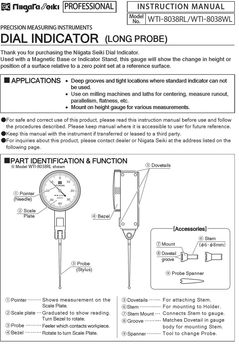
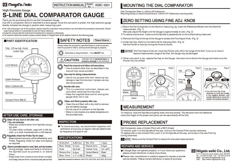
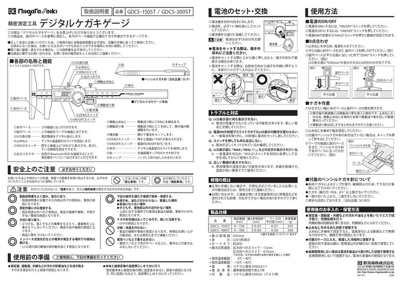
Niigata seiki WCDI-10D User manual

■TROUBLESHOOTING
■MEASUREMENT
■OPERATION ※Measure absolute dimension of workpiece
ABSOLUTE MODE (ABS)
■
SPECIFICATIONS
ABS/SET
MIN C AL
ZERO/ON
ABS/SET
MIN C AL
ZERO/ON
ABS
OO ■ASSEMBLY
ACCESSORIES
ABS/SET
MIN CA L
ZERO/ON
ABS
OO
ba
ABS/SET
MIN CAL
ZERO/ON
ABS
OO
ABS/SET
MIN CAL
ZERO/ON
ABS
OO 
ABS/SET
MIN CAL
ZERO/ON
OO
Niigata Seiki Co., Ltd.
5-3-14, Tsukanome, Sanjo, Niigata, Japan, 955-0055
Tel. : +81-256-33-5522 Fax. : +81-256-33-5518
MAIL intl.sales@niigataseiki.co.jp
URL http://www.niigataseiki.co.jp
Adjacent error
DIGITAL BORE GAUGE
Model No.:WCDI-10D/WCDI-18D
<
combined
>
【Accessories】*Including supplied Digital Gauge
※Not including quantization error (±1 count)
①Loosen the Clamp Screw and insert
the Digital Indicator into the gauge
body. Tighten the Clamp Screw to
secure.
※After attaching, press the [ZERO/ON]
Button on the Digital Indicator to turn on
power. Confirm that the displayed
reading changes by gently squeezing the
measurement head. If necessary, adjust
the depth that the Digital Indicator is
inserted into the gauge body.
②Select the Extension Rod, washer (WCDI-18Donly)for the desired
measurement range.
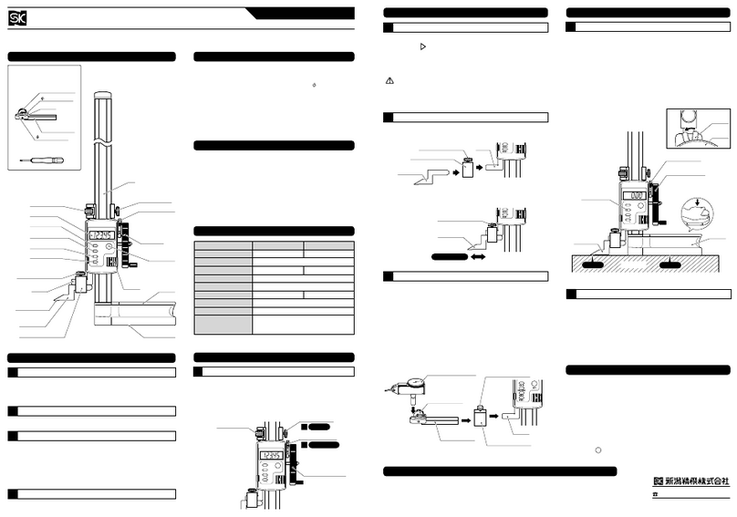
■PART IDENTIFICATION
WCDI
-
10D
6
-
10
12
5
0.7
WCDI
-
18D
10
-
18
0 . 0 0 2
3
12
5
0 . 0 0 2
3
0.9
0〜6.0
【WCDI-18D】【WCDI-10D】Spanner
Spanner
Nut
1. Use the Spanner to loosen the
Nut at the bottom of
Measurement Head.
2. Install the Extension Rod and
tighten.
Attach the Extension Rod,
Washer to the bottom of the
Measurement Head and tighten
with the Spanner.
Ex. Rod
8.5mm +Washer 0.5mm
(WCDI-18D only)Extension Rod
(WCDI-10D)(WCDI-18D)Spanner
(WCDI-10D)(WCDI-18D)NOTICE
■INSERTING・REPLACING BATTERY
■AUTO OFF DELAY
Use only CR2032 type lithiumbutton cell.
NOTICE
Auto Off Delay
2 6 5 3 0 0
**※※*※①Press and hold the [ZERO/ON]Button to turn power OFF.
②Press and hold [ABS/SET]and [ZERO/ON]Buttons at the
same time.
③When「-----」is displayed, ❶release the [ZERO/ON]Button,
❷then release the [ABS/SET]Button in that sequence.
④The Auto Off Delay time will be displayed. Press [ABS/SET]
to change.
※Each press of the [ABS/SET]Button will change the delay
by 1/2 hr. (30 min.)from 0 to 6 hr.
⑤Press [ZERO/ON]when done and display will return to the
measurement screen.
※Once set, the delay time is saved even when power is OFF.
Thank you for purchasing the Digital Bore Gauge.
Please read this manual thoroughly before use for proper operation.
Instruction Manual
●This is a precision instrument, handle with care.
●Do not disassemble or modify.
●Keep instrument away from water and oil.
●Use only with supplied Extension Rods and Washer.
●Keep instrument away from direct sunlight and high temperatures
such as in a car, or near a stove or heat source.
●After use, remove any dirt or cutting chips and apply rust
preventative oil to Extension Rod and Washer. When not in use
store in supplied storage case.
●This product is for measuring inside diameter; use only as directed.
Improper use may cause accident or injury.
●Avoid using in high electric fields, such as near fluorescent lights or
switching power supplies. Electrical interference may cause
incorrect readings.
Pull out the case from the two
side edges to remove. Insert
battery with
(
+
)
side facing
down.
Battery
Case
Battery
(CR2032)※1:Not Used
※2:"0.01" indicates the resolution of
the display's digital bar graph.
The bar graph display will
change with each 0.01mm change in the measured value.
※Spanners shown in drawing
above vary slightly in
appearance, but function will
be same.
Ex.)
WCDI-10D set to 8.5mm
Ex.)
WCDI-18D set to 14.5mm
Length below Handle:
100mm
Extension
Rod
Measurement
Head Guide
Probe
Tip
Probe
Tip
[ZERO/ON]
Button
[CAL]Button
Handle
Cap
Length below
Handle:
※1※2
[MIN]Button
[ABS/SET]
Button
Clamp
Screw
Gauge
(Digital Indicator)
LCD Display
Extension
Rod
Measurement
Head
50mm
(μm)(mm)(mm)(μm)(μm)(mm)(g)Measuring Range
Resolution
Wide range accuracy
Repeatability
Single Stroke Range
Weight
Model No. (hr)●Extension Rods
 WCDI
-
10D ・・・・6・6.5・7・7.5・8・8.5・9・9.5・10mm(9 pieces) WCDI
-
18D ・・・・10・11・12・13・14・15・16・17・18mm(9 pieces)●Washer ・・・・・・・0.5mm(WCDI-18D only)●Spanner ・・・・・・1x
●Battery ・・・・・・・CR2032 Lithium button cell, 1x(for test)Ex. Rod
14mm
Washer
0.5mm
Clamp
Screw
INSERT
Shaft (Fig.1)(Fig.2)(Fig.3)(Fig.4)(Fig.5)(Fig.6)For accurate measurements, follow the procedure described below.
①In cross section perpendicular to the axis of the bore, as shown in Figure 1, position the gauge along diameter ⓐ. This is the
maximum distance, and at this point the Indicator will read the maximum value. The Guide will automatically position the Measurement
Head to diameter ⓐwhen inserted.
※WCDI-10D does not have a guide on the Measurement Head so please manually position at this maximum value.
②In cross section parallel to the axis of the bore through diameter ⓐ, position the indicator to minimize the distance ⓑ. (Figure 2)
In this position the Indicator will read the minimum value. This position must be manually determined by pivoting the Gauge as shown
in Figure 3 while watching the Indicator to find the minimum value.
①Before use, please make sure the Measurement Head components are not loose and tighten if necessary.
②Clean the Measurement Head and the ID of a Ring Gauge Standard using parts cleaner or cleaning solution.
③Press the [ZERO/ON]Button to turn on power. ※A long press to the [ZERO/ON]Button will turn power off.
①Turn on power. If “”or “”symbols are displayed on the LCD,
press the [MIN]Button to turn off. If “ABS”is displayed press the
[ABS/SET]Button to turn off.
②Insert the Measurement Head into the Ring Gauge Standard and press
[MIN]Button to put the Indicator into minimum-mode. Slowly pivot the
gauge (Figure 3)to display the minimum value.
③Remove the gauge from the Ring Gauge and press the [CAL]Button until
“OK”is displayed.
Preparation for measurement is now complete.
④Put the gauge into the workpiece to be measured, and pivot the gauge
slowly. (Figure 3)The LCD will display the difference between the
measured workpiece and the calibration standard. (Figure 6)
※Press the [ON/ZERO]Button momentarily to reset display in preparation
to measure the next workpiece.
①Turn on power. If the “”or “”symbols are displayed on the LCD, press the [MIN]Button to turn off.
②Adjust the “SET”value of the Bore Gauge to match the ID of the Ring Gauge Standard. Press and hold the [ABS/SET]Button until
“SET”blinks on the display.
③Continue holding the [ABS/SET]Button and the display character to the left will blink. Use a short press of the [ABS/SET]Button to
change the value, and a long press to change the character being modified. Repeat this process to enter the dimension of the Ring
Gauge Standard on the LCD display. (Figure 4)
④When the value is entered the flashing position will return to “SET”. A short
press of the [ABS/SET]Button to turn off the flashing.
⑤Insert the Measurement Head into the Ring Gauge Standard and press the
[MIN]Button to put the Indicator into minimum-mode. Slowly pivot the
gauge (Figure 3)to display the minimum value.
⑥Remove the gauge from the Ring Gauge and press the [CAL]Button until
“OK”is displayed.
Preparation for measurement is now complete.
⑦Put the gauge into the workpiece to be measured, and pivot the gauge
slowly. (Figure 3)The LCD will display the measured value. (Figure 5)
※Press the [ON/ZERO]Button momentarily to reset display in preparation
to measure the next workpiece.
※Difference between workpiece and reference
COMPARATIVE MEASUREMENTS
ERROR CORRECTIVE ACTION ※If problem persists, or if you have any
questions, please contact distributor.
※Please note, manufacturer is unable to
respond to inquires or provide service
directly. Please contact distributor.
●LCD does not display
●Displayed value is unstable
●Display is not clear ●Cycle power by removing and
replacing battery.
●Replace battery with new one.
Work-
piece
Work-
piece
Diff. between Work-
piece and Reference
Set to match
Workpiece I.D. value
Ring Gauge
Standard
ABS/SET
MIN C AL
ZERO/ON
ABS/SET
MIN C AL
ZERO/ON
ABS
OO
ABS/SET
MIN CAL
ZERO/ON
ABS
OO
ABS/SET
MIN CAL
ZERO/ON
ABS
OO 
ABS/SET
MIN CAL
ZERO/ON
OO
ABS/SET
MIN CA L
ZERO/ON
ABS
OO
■本体の組み付け●換えロッド WCDI-10D・・・6・6.5・7・7.5・8・8.5・9・9.5・10mm(計9本) WCDI-18D・・・10・11・12・13・14・15・16・17・18mm(計9本)●ワッシャ・・・・・・・0.5mm(WCDI-18Dのみ)●スパナ・・・・・・・・1本●電 池・・・・・・・・CR2032(コイン型リチウム電池:テスト用)×1個広範囲精度(μm)デジタルシリンダゲージ۽ᘹ⬀nrqpnrya⬂Ԁᘈ⬄
この度はデジタルシリンダゲージをお買上げ頂きありがとうございます。ご使用前に、本書をよくお読み頂き正しくお使いくださいますようお願い申し上げます。ٯඏ‑ད࿉
付属品【付属品】にぎりLCD表示部ZERO/ONボタンCALボタンMINボタンABS/SETボタン取付ねじキャップ取付ねじ:付属のデジタルインジケータ(指示器)を含めた値です。*※量子化誤差(±1カウント)含まず①取付ねじをゆるめ、指示器を本体に差し込みます。取付ねじを締めて固定してください。※固定後、ZERO/ONボタンを押して電源を入れ、測定子を押してLCD表示部の数値が変わることを確認してください。上手く動作しない場合は、指示器の差込深さを再度調整してください。②測定する寸法に合わせて、換えロッド・ワッシャ(WCDI-18Dのみ)を選択します。■各部の名称■仕様差し込む
WCDI-10D6-101250.7WCDI-18D10-180.00231250.00230.90〜6.0換えロッド外筒
にぎり下長さ
50mm
測定部測定子【WCDI-18D】【WCDI-10D】
にぎり下長さ100mm
換えロッド測定部案内板測定子スパナスパナナット1.付属のスパナで測定部下部のナットをゆるめてください。2.換えロッドを差し込み、ナットを締めて固定してください。付属のスパナで換えロッド・ワッシャを測定部に固定してください。換えロッド8.5mm換えロッド14mmワッシャ0.5mm+例)WCDI-10D8.5mm測定用ワッシャ0.5mm(WCDI-18Dのみ)換えロッド(WCDI-10D)(WCDI-18D)スパナ※スパナの形状は上図と若干 異なる場合がありますが、 使用上問題ありません。(WCDI-10D)(WCDI-18D)指示器※1(デジタルインジケータ)※2●精密機器ですので、落としたりぶつけたりしないでください。●分解・改造はしないでください。●水や油のかかるところで使用しないでください。●換えロッド・ワッシャなどは付属のものを使用し、他との併用は避けてください。●直射日光の当たる場所や炎天下の車の中、火のそばなどに放置しないでください。●使用後は柔らかい布などでゴミや切粉などを取り除き、換えロッド・ワッシャなどは防錆処理をして、収納ケースの元の位置に保管してください。●本製品は内径測定用機器です。用途以外のご使用は、事故やけがの原因となりますので絶対におやめください。●インバータ式蛍光灯などの電界が発生する場所でのご使用は避けてください。LCD表示部の数値が誤作動を起こす原因となります。ご注意■電池のセット・交換■オートオフ時間の設定電池蓋両側をツマミながら引き出し、(+)側が下になるよう電池をセットして、電池蓋を戻してください。電池は必ずCR2032(コイン型リチウム電池)をお使いください。ご注意電池蓋電池(CR2032)品    番測定範囲(mm)目     量(mm)隣接誤差(μm)繰返し精密度(μm)
測定子の有効ストローク
(mm)オートオフ設定(時間)265300質     量(g)**※※*※ba(図1)(図3)(図2)マスタとなるリングゲージワーク数値を合わせるワークの内径を表示ワークマスタとなるリングゲージとの差を表示■トラブルと対応トラブルの内容対応策LCD表示部に何も表示されない表示が安定しない表示が不明確である電池を入れ直してください。新しい電池と交換してください。●●●●●※症状が改善されない場合や不明な点がございましたらお買い上げの販売店、または当社までご連絡ください。※お問い合わせや、ご連絡が無いまま直接修理品などを送付されても処理、対応ができない場合がありますのでご了承ください。I382-K32401①ご使用の前に、測定部と外筒の間がゆるんでいないか確認し、ゆるんでいたら締め付けてください。②測定子を含めた測定部と、基準リングゲージの内径をパーツクリーナーなどの洗浄液で洗浄します。③ZERO/ONボタンを押して、電源をONにしてください。※電源をOFFにする時は、ZERO/ONボタンを長押ししてください。■測定方法について■使用方法①電源をONにします。LCD表示部に『 』、『 』のマークが表示されている場合は、MINボタンを押してマークを消してください。②マスタとなるリングゲージの数値に、シリンダゲージの数値を合わせます。ABS/SETボタンを長押ししてください。SETボタンが点滅します。③長押しを続けると、点滅位置が変わって行きます。変更したい数値の位置に点滅が移動して来たら、一度ABS/SETボタンを放し、今度は短く押してください。数値が変わります。 これを繰り返し、マスタとなるリングゲージに表示されている実寸法と、LCD表示部の数値を一致させてください。(図4)④数値が一致したら点滅位置を『SET』まで戻し、ABS/SETボタンを短く押して点滅を解除してください。⑤測定部をマスタとなるリングゲージに入れ、MINボタンを押して最小値測定モードにします。(図3)のようにシリンダゲージをゆっくりと振り、最小値を表示させてください。⑥測定部をマスタとなるリングゲージから抜き、CALボタンを長押ししてください。『OK』が表示されます。 これで測定の準備が完了しました。⑦ワークに測定子を入れ、(図3)のようにシリンダゲージをゆっくりと振って、測定してください。LCD表示部に、測定値が表示されます。(図5) ※次のワークを測定する際は、ZERO/ONボタンを一度押してください。絶対測定(ABS)※ワークのサイズを絶対値で表示します。※ワークのサイズをマスタとなるリングゲージとの差で表示します。①電源をONにします。LCD表示部に『ABS』、『  』、『  』のマークが表示されている場合は、ABS/SETボタンとMINボタンを押してマークを消してください。②測定部をマスタとなるリングゲージに入れ、MINボタンを押して最小値測定モードにします。
 
(図3)のようにシリンダゲージをゆっくりと振り、最小値を表示させてください。③測定部をマスタとなるリングゲージから抜き、CALボタンを長押ししてください。『OK』が表示されます。これで測定の準備が完了しました。④ワークに測定子を入れ、(図3)のようにシリンダゲージをゆっくりと振って、測定してください。LCD表示部に、マスタとなるリングゲージとの差が表示されます。(図6) ※次のワークを測定する際は、ZERO/ONボタンを一度押してください。正確な数値を測定するために、測定は下記の手順で行ってください。①円筒の軸に垂直な断面において、直径䒏は最大値となり、指示器は最大値を表示します。(図1)この直径䒏は、可動する案内板によって自動的に求められます。※WCDI-10Dには案内板がありません。手動で最大値を示す位置を探してください。②直径䒏を通る円筒の軸に平行な断面において、直径书は最小値となり、指示器は最小値を表示します。(図2)この直径书は、手動で求めます。シリンダゲージを(図3)のように振り、指示器が最小値を示す点を探してください。比較測定(図4)(図5)(図6)
〒955-0055
新潟県三条市塚野目5丁目3番14号
(0256)33-5502(代)FAX(0256)33-5528
URL http://www.niigataseiki.co.jp
※1:このボタンは使用しません。※2:「0.01」表示は液晶表示部外周のバーグラフの単位です。測定値に0.01mmの変動があった場合それに応じて、バーグラフも1本増減します。例)WCDI-18D14.5mm測定用①ZERO/ONボタンを長押しし、電源をOFFにします。②ABS/SETボタンとZERO/ONボタンを同時に押します。③LCD表示部に「-----」が表示されたら、❶ZERO/ONボタン→❷ABS/SETボタンの順に放します。④LCD表示部に設定時間が表示されるので、ABS/SETボタンを押し、希望の時間を表示させます。※ABS/SETボタンを押すたびに「0.5時間(30分)」ずつオートオフ時間が切り替わります。(0〜6.0時間)⑤ZERO/ONボタンを押し、画面が測定画面に切り替わったら設定完了です。※電源をOFFにしても、設定時間は記憶されています。

This manual suits for next models

1

Other Niigata seiki Measuring Instrument manuals

Niigata seiki GDCS-150D User manual

Niigata seiki

Niigata seiki GDCS-150D User manual

Niigata seiki DUP-360AN User manual

Niigata seiki

Niigata seiki DUP-360AN User manual

Niigata seiki GDCS-150D User manual

Niigata seiki

Niigata seiki GDCS-150D User manual

Niigata seiki KAIDAN GVC-10 User manual

Niigata seiki

Niigata seiki KAIDAN GVC-10 User manual

Niigata seiki N-5AS User manual

Niigata seiki

Niigata seiki N-5AS User manual

Niigata seiki LSL-26 User manual

Niigata seiki

Niigata seiki LSL-26 User manual

Niigata seiki WDI-3058SP User manual

Niigata seiki

Niigata seiki WDI-3058SP User manual

Niigata seiki GDCP-200AA User manual

Niigata seiki

Niigata seiki GDCP-200AA User manual

Niigata seiki GDCS Series User manual

Niigata seiki

Niigata seiki GDCS Series User manual

Niigata seiki SIC EMH-25F User manual

Niigata seiki

Niigata seiki SIC EMH-25F User manual

Niigata seiki WTI Series User manual

Niigata seiki

Niigata seiki WTI Series User manual

Niigata seiki GDCS-150IK2 User manual

Niigata seiki

Niigata seiki GDCS-150IK2 User manual

Niigata seiki CDI-50 User manual

Niigata seiki

Niigata seiki CDI-50 User manual

Niigata seiki GDCS-150DS User manual

Niigata seiki

Niigata seiki GDCS-150DS User manual

Niigata seiki SCDI S Series User manual

Niigata seiki

Niigata seiki SCDI S Series User manual

Niigata seiki DTW-DG02 User manual

Niigata seiki

Niigata seiki DTW-DG02 User manual

Niigata seiki CJU BKD Series User manual

Niigata seiki

Niigata seiki CJU BKD Series User manual

Niigata seiki CDI-18D User manual

Niigata seiki

Niigata seiki CDI-18D User manual

Niigata seiki D IP67S Series User manual

Niigata seiki

Niigata seiki D IP67S Series User manual

Niigata seiki D HL Series User manual

Niigata seiki

Niigata seiki D HL Series User manual

Niigata seiki GDCS-150DR User manual

Niigata seiki

Niigata seiki GDCS-150DR User manual

Niigata seiki SCG Series User manual

Niigata seiki

Niigata seiki SCG Series User manual

Niigata seiki WR-100 User manual

Niigata seiki

Niigata seiki WR-100 User manual

Niigata seiki CJU BKD Series User manual

Niigata seiki

Niigata seiki CJU BKD Series User manual

Popular Measuring Instrument manuals by other brands

EyeQue VisionCheck EQ102 product manual

EyeQue

EyeQue VisionCheck EQ102 product manual

Topcon RL-H1Sa instruction manual

Topcon

Topcon RL-H1Sa instruction manual

Bindicator MP Series Installation & operation manual

Bindicator

Bindicator MP Series Installation & operation manual

AlphaLab TriField EM100 quick start guide

AlphaLab

AlphaLab TriField EM100 quick start guide

Emerson Rosemount 8800D Series Reference manual

Emerson

Emerson Rosemount 8800D Series Reference manual

Itm 89088 instruction manual

Itm

Itm 89088 instruction manual

YOKOGAWA Power Series Plus IM 2493AAA-1 user manual

YOKOGAWA

YOKOGAWA Power Series Plus IM 2493AAA-1 user manual

KROHNE OPTISWIRL 4200 quick start

KROHNE

KROHNE OPTISWIRL 4200 quick start

MKS Granville-Phillips Series 275 instruction manual

MKS

MKS Granville-Phillips Series 275 instruction manual

PCB Piezotronics 356A43 Installation and operating manual

PCB Piezotronics

PCB Piezotronics 356A43 Installation and operating manual

AEMC instruments 502 manual

AEMC instruments

AEMC instruments 502 manual

Endress+Hauser PROline promag 53 operating instructions

Endress+Hauser

Endress+Hauser PROline promag 53 operating instructions

LumaSense 140 Series Manual addendum

LumaSense

LumaSense 140 Series Manual addendum

AEMC instruments MN103 user manual

AEMC instruments

AEMC instruments MN103 user manual

Elster BK-G Series Operating instructions for operators and installers

Elster

Elster BK-G Series Operating instructions for operators and installers

Starrett W733.1 user manual

Starrett

Starrett W733.1 user manual

STONEX R2W PLUS 500 instruction manual

STONEX

STONEX R2W PLUS 500 instruction manual

OHAUS MB90 quick start guide

OHAUS

OHAUS MB90 quick start guide

manuals.online logo
manuals.online logoBrands
  • About & Mission
  • Contact us
  • Privacy Policy
  • Terms and Conditions

Copyright 2025 Manuals.Online. All Rights Reserved.