KICK ASS KAF-30DS User manual

30L DC COMPRESSOR
DRAWER FRIDGE
KAF-30DS

Thank You For Purchasing A
KickAss® Fridge / Freezer
Features:
Please ensure all safety and operational instructions are read carefully to get the
maximum benefit from your new fridge.
Digital electronic thermostat with LED temperature display
Reliable refrigeration system with Secop compressor
Efficient electronic technology, low energy consumption
Multi-voltage system (DC 12-24 Volt) and (AC 220-240 Volt)
Adjustable low voltage battery protection
IMPORTANT SAFETY SYMBOLS
Warning! - Safety Directive
Failure to observe this directive could lead to serious injury.
Caution! - Safety Directive
Failure to observe this directive could lead to injury or damage to the
appliance.
Note! - Important Information
Failure to observe this note may lead to damage to the appliance or
impede performance.
1

2

TECHNICAL DATA (STANDARD CONFIGURATIONS)
Operating voltage 12 o 24 VDC
Refrigerant gas and charge R134a 0,044 kg - CFC Free (CO2 eq. 0,063 t)
Dimensions 260 x 440 x 695 (mm)
Net weight 18 Kg
Installed power 45 Watt
SPECIFICATIONS
PRODUCT FEATURES
Slide out drawer
Drawer latch
Soft touch controls
Power connection
Compressor cooling vents
3

INSTALLATION
Mounting
KickAss DRAWER refrigerators have been designed and constructed exclusively for
recessed installation and installation that is in compliance with standard dimensions. The
refrigerator must always be in a horizontal position, with the compressor’s rubber feet at
the bottom. The compressor is capable of functioning at angles of up to 30°. The
compressor can become damaged with any higher inclinations.
Ventilation
It is extremely important for the compressor/condensing unit located behind the
refrigerator to be well ventilated so that the fresh air can enter at the bottom and
pass behind the refrigerator, with the hot air being allowed to escape from the top or
sides.
Electrical Connections
• Before turning on the appliance, check to make sure that the voltage of the electrical
system and/or battery complies with that which is indicated on the unit’s data plate.
• Connect the refrigerator directly to the battery or to the relative main switch and make
sure that the system is equipped with an electric device that’s capable of protecting the
circuit against possible overcurrents.
• The product is supplied with a 10 A fuse. A separate switch that simultaneously
disconnects the power cables must be installed upstream from the refrigerator. Check to
make sure that this switch supports the 10 A current load.
SIZE OF THE ELECTRICAL CABLES
Always use cables of a suitable cross-section. The minimum cross-sections are listed in the table
below:
Cross-
section in
mm²
AWG section Max 12 V cable length m/ft Max 24V cable length m/ft
2.5 13 2.5/8 5/16
4 11 4/13 8/26
6 9 6/19 12/39
10 8 10/33 20/66
For system protection, the fuse must be installed in the positive wires (+) as close as possible to
the battery. We recommend using 15 A fuses for 12 V and 7.5 A fuses for 24 V. If using a main
switch, it must be able to withstand a minimum current of 20 A. Avoid extra junctions in wiring to
prevent voltage drops that can influence battery protection settings.
4

TEMPERATURE ADJUSTMENT SETTINGS
TEMPERATURE REGULATION WITH DIGITAL DISPLAY
4 3 2 1
DISPLAY FUNCTIONS
• Switching on: Press and hold the 1 button for 4 seconds.
• Shut-down (Stand-By): Press and hold the 1 button for 4 seconds.
• Internal temperature adjustment buttons 2 and 3.
• Access to programming menu [Pro].
TEMPERATURE SETTING
Switch on the refrigerator, set the desired temperature using the 2 button to increase or 3 to
decrease the temperature, which will be saved automatically.
MENU FUNCTION [PRO]
The Pro menu allows for changes to the following data: offset 1, offset 2, offset 3, battery
protection (For offset information see page 7).
To access the Pro menu, press the 2 and 3 buttons simultaneously for 4 seconds. The message
will then appear on the digital display. Press the 1 button to confirm entry into the
menu.
The offset1 value will appear. This value can be changed from +8 to -8 using buttons 2 and 3.
Press 1 to confirm the new data entered and go to setting for the next parameter.
The offset2 value will appear. This value can be changed from +8 to -8 using buttons 2 and 3.
Press 1 to confirm the new data entered and go to setting for the next parameter.
The offset3 value will appear. This value can be changed from +8 to -8 using buttons 2 and 3.
Press 1 to confirm the new data entered and go to setting for the next parameter.
The figure shown, or or , refers to the level of battery saving set. The value can be
modified using button 2 or 3.
Press 1 to confirm the new data entered and go to setting for the next parameter.
The figure shown or refers to the selection of the temperature scale,
Celsius or Fahrenheit, the selection of the factory setting is in Celsius, the value can be changed
by pressing the button 2 or 3.
To exit from the Pro menu, wait a few seconds until the display shuts down. Data will be saved
automatically.
5

GRAPHICAL DISPLAY OF THE SEQUENCE FOR SETTING THE PRO MENU
6

OFFSET
After a few hours of refrigeration system operation, insert a digital thermometer (not included)
inside the compartment in the position where you wish to have a more precise temperature and
check that the temperature indicated on the display coincides with the temperature read on the
digital thermometer. If it does not coincide, change the Offset related to the temperature you wish
to reach inside the compartment until the temperature read on the display coincides with the
temperature indicated on the digital thermometer.
Offset Temperature Interval
1 T ≥ -6°C
2 -12°C ≤ T ≤ -7°C
3 T ≤ -13°C
Data which is used to align the temperature shown on the display with the actual internal
temperature. Adjustment for each offset can vary from -8 / +8.
POWER OPTIONS
LOW VOLTAGE PROTECTION
In order to prevent excessive battery depletion, a protection device shuts off the compressor in
case of insufficient voltage and turns it back on when the voltage in the system increases after the
batteries have been charged.
Battery Protection
Battery level Digital
Display
12 Vdc 24 Vdc
Cut-Out
Comp. off
Cut-In
Comp. on
Cut-Out
Comp. off
Cut-In
Comp. on
Low 9.6 10.6 21.3 22.7
Medium 11.1 12.1 22.3 23.7
High 11.8 12.8 24.3 25.7
7

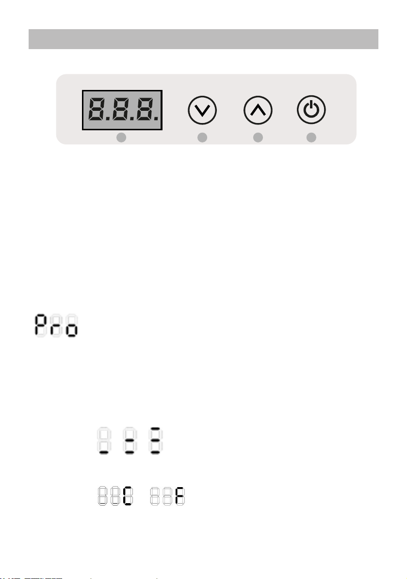
DISPLAY ERRORS TABLE
TROUBLESHOOTING
Error Cause
E1 Insufficient voltage (Volts below the cut-in / cut-out value)
E2 Defective fan
E3 Control unit error or compressor blocked
E4 The refrigeration system is too loaded with gas and/or the compressor is
running at a number of revolutions that is too low
E5 Room temperature is too high
E6 Internal temperature sensor error
Defect Possible cause Intervention
The refrigerator does not
cool, the compressor will
not start.
No electrical power. Battery
in poor condition. Faulty
thermostat. Defective
electronic control unit.
Check to make sure that the electronic
control unit is receiving sufficient power
and voltage; check the fuse. Verify that
the internal lighting is working and that
the compressor is receiving power.
Check the cables, lugs and connectors.
Verify that the battery is charging
properly. Check the thermostat: Bridge
T - C with a separate cable. If the
compressor will not start, its electronics
are probably defective. Replace. If the
compressor starts up with the bridge,
the thermostat is defective. Replace
the thermostat.
The compressor only
performs brief attempts at
starting up.
There is insufficient voltage or
else a drop in voltage during
the attempt to start. The
protection device is activated.
The Batteries are drained.
Check the cables and connections;
remove any traces of oxidation or
corrosion. Charge the batteries, start
the motor or connect the battery
charger.
The compressor functions
but doesn’t cool.
Loss of refrigerant through
the evaporator or the
tubing. Tubing clogged.
Carry out a leak check and repair
any leaks, drain and refill the proper
amount of R134a refrigerant. (This
operation must be carried out by a
qualified technician.)
The compressor runs for
a long time but doesn’t
cool properly (reduced
efficiency).
Insufficient ventilation,
the condensation unit is
overheating. The fan is not
working properly. There is too
much frost on the evaporator.
The door does not close
properly and lets in warm,
moist air. The condenser is
blocked by dust.
Increase the ventilation. Replace
the fan. Defrost the unit. Correct the
position of the door and check the
gasket. Clean the condensing unit.
GENERAL TROUBLESHOOTING
8

The fuse blows. The wrong fuse is being
used. Defective electronic
control unit.
Check the fuse: see table in section
4.4. Replace the electronic control unit.
The compressor is
operating intermittently.
Battery low or electrical
cables in poor condition.
Check wiring conditions, examining for
loose connections, rust or corosion. If
wiring needs to be replaced, see the
manual for correct sizing. If wiring is in
good condition, check battery function
and replace if in poor condition.
The compressor never
stops (correct fridge
performance)
Incorrect thermostat
connection on the electronic
control unit. Thermostat
broken. Condensation
is not working properly,
evaporator cools but not
enough to cause the
thermostat to stop the
compressor.
Rotate the thermostat to off position. If
the refrigerator continues to function,
then there is continuity on the control
unit. Correct the problem on thermostat
connections (make sure the bridge
is present on C and P and not on C
and T on the electronic control unit).
Rotate the thermostat to off position.
If the compressor switches off but it is
impossible to regulate temperature,
replace the thermostat or recharge the
cooling system.
The compressor never
stops (poor fridge
performance)
Environment very hot +
insufficient ventilation or
little gas in the refrigerant
circuit.
Check ventilation. The compressor
must be installed in a well-ventilated
location. If possible, remove the
refrigerator from the installation hole.
If the refrigerator operates better,
improve ventilation, consulting the
manual for correct installation. If
ventilation is instead optimal, check
for the presence of gas in the system,
contacting a specialised technician.
9

THANK YOU FOR CHOOSING
KickAss® is committed to providing you with the
most up to date product information. As printed
material is harder to update we have created an online
user guide portal including videos, user guides and
product tips so you can view or download the latest
product information at any time. This also helps to save
our environment which we are committed to just as
much as we are committed to our customer service.
To get started with this product, please visit
and search for your SKU code
ONLINE USER GUIDES
SCAN QR CODE
USERGUIDES.KICKASS.COM.AU

This product is warranted for 3 years from the date of purchase. In Australia, our
goods come with guarantees that cannot be excluded under the Australian
Consumer Law. You are entitled to a replacement or refund for a major failure and
compensation for any other reasonably foreseeable loss or damage. You are also
entitled to have the goods repaired or replaced if the goods fail to be of acceptable
quality and the failure does not amount to a major failure.
Warranty does not cover products that have not been used in accordance with the
KickAss® user guide or are outside the warranty terms and conditions.
AUSTRALIAN DIRECT PRODUCT QUALITY
QUESTIONS AND COMMENTS
Customer Support
For any technical or warranty enquires
please visit our customer service
portal at:
warranty.kickass.com.au
Please visit us at kickass.com.au or email us at [email protected]
This KickAss product comes with a 3 year warranty on the
whole unit, for your peace of mind. In the unlikely event this
product fails when used according to our user guide, we
will either repair or replace it. For full warranty terms and
conditions on this product, please see the user guide at:
userguides.kickass.com.au
WARRANTY INFORMATION

Table of contents
Other KICK ASS Refrigerator manuals