Page 3 of 3 DATA SHEET DC-9102E-KID
Issue 1.0
Specifications
Operating Voltage 24VDC (12VDC ~28VDC)
Standby Current ≤60mµA
Alarm Current ≤55mA
Fire LED Red, periodical flash when polling when LED status is set to
‘ON’. No illumination when the status is set to ‘OFF’. Periodical
two flashes when in fault or sensing chamber is dirty. Steady
illumination when in alarm.
Remote indication output Polarity-sensitive output, directly connecting with remote
indicator (built in 10k resistor in series, max. output current is
2mA); no illumination when in nofrmal state; flash when in alarm.
Max. ripple voltage 2V (peak to peak value)
Alarm Reset Instant power down 910s mon, 1.0VDC max.
Sensitivity setting The sensitivity can be set by hand held programmer. There are
two sensitivity levels: level 1 (default ) and level 2.
Wiring Two-wire, polarity sensitive.
Ingress Protection Rating IP2X
Environmental Temperature -10˚C~+50˚C
Relative Humidity ≤95%, non-condensing
Material ABS
Dimension Diameter : 100mm Height : 44.5mm (without base)
Mounting Hole Distance 45mm ~ 75mm
Weight Approx. 110g
Ordering information
Part number Description Ship Wt., lb
(kg)
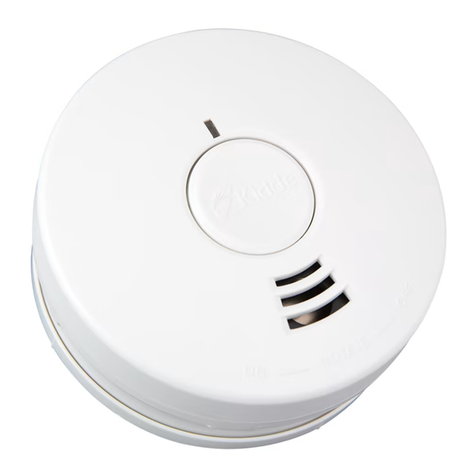
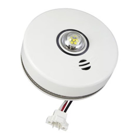
DC-9102E-KID Conventional Photoelectric Smoke Detector
Before performing maintenance ensure the proper authorities are notified that the
system is undergoing maintenance and will temporarily be out of service. Disable the
zone or system undergoing maintenance to avoid any unwanted alarms.
Prior to commissioning ensure the dust covers are left on the detectors and measures
are taken to keep the detectors free from dust, dampness and corrosion.
Detector should be cleaned at least once a year to ensure normal operation of the
system.
The detector should be tested after any cleaning or when replaced.
Protect the metal component on the PCB against damp and improper distortion.
If nuisance alarms are often found of the detector on site, the sensing chamber should
be cleaned and replaced when necessary.
a) Open the top cover of detector, and draw out the sensing chamber by slightly
lifting its two sides using a flat screwdriver, as shown in Fig. 7.
b) Clean the sensing chamber by using an alcohol
cotton swab, clean water and brush. Please
note not to leave any cotton in the chamber.
c) Re-install the sensing chamber and top cover.
Maintenance
FIGURE 7
Accessories and Tools
Module Name Remarks
P-9910B Handheld Programmer Order separately
DB-01 Base Order separately
Australia & New Zealand
Phone: 1800 672 171
Outside Australia: +61 3 9518 5588
Email:cs@resecurityproducts.zendesk.com
Web: www.kidde.com.au
Head Oce
10 Ferntree Place
Notting Hill, Victoria 3168
Australia
©2021Carrier.Allrightsreserved.
KiddeAustraliaisaCarriercompany.
