nect up to a total of 6 remote signaling evices an /or relay mo ules.
• When mixing mo els which have battery backup (1275, 1276, 1285, 1296,
i12040, i12040A, i12060, i12060A, i12080, i12080A, i4618, i4618A, PE120,
P12040, PI2000, PI2010, KN-COPE-i, KN-SM-FM-i, KN-COSM-IB,
KN-COSM-IBA, HD135F, KN-COB-IC, KN-COP-IC, i12010S, i12010SCO,
RF-SM-ACDC) with mo els without battery backup, (1235, i12020, i12020A,
KN-COSM-I,120X, SM120X, CO120X, SL177i, SLED177i) be a vise that the
mo els without battery backup will not respon uring an AC power failure.
• The maximum wire run istance between the first an last unit in an intercon-
necte system is 1000 feet.
• Figure 4 illustrates interconnection wiring. Improper connection will result in
amage to the alarm, failure to operate, or a shock hazar .
• Make certain alarms are wire to a continuous (non-switche ) power line.
NOTE: Use stan ar UL liste househol wire (as require by local co es) avail-
able at all electrical supply stores an most har ware stores.
FIGURE 4 INTERCONNECT WIRING DIAGRAM
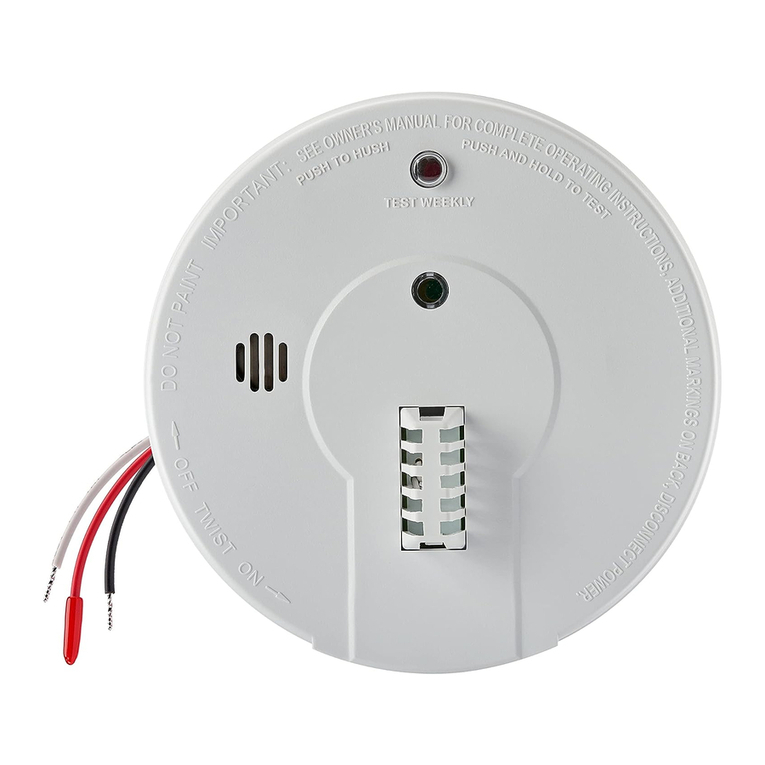
WIRES ON ALARM HARNESS CONNECTED TO
Black Hot Si e of AC Line
White Neutral Si e of AC Line
Re Interconnect Lines (Re Wires) of Other
Units in the Multiple Station Set up
BATTERY INSTALLATION
See MAINTENANCE (section 6) for battery installation.
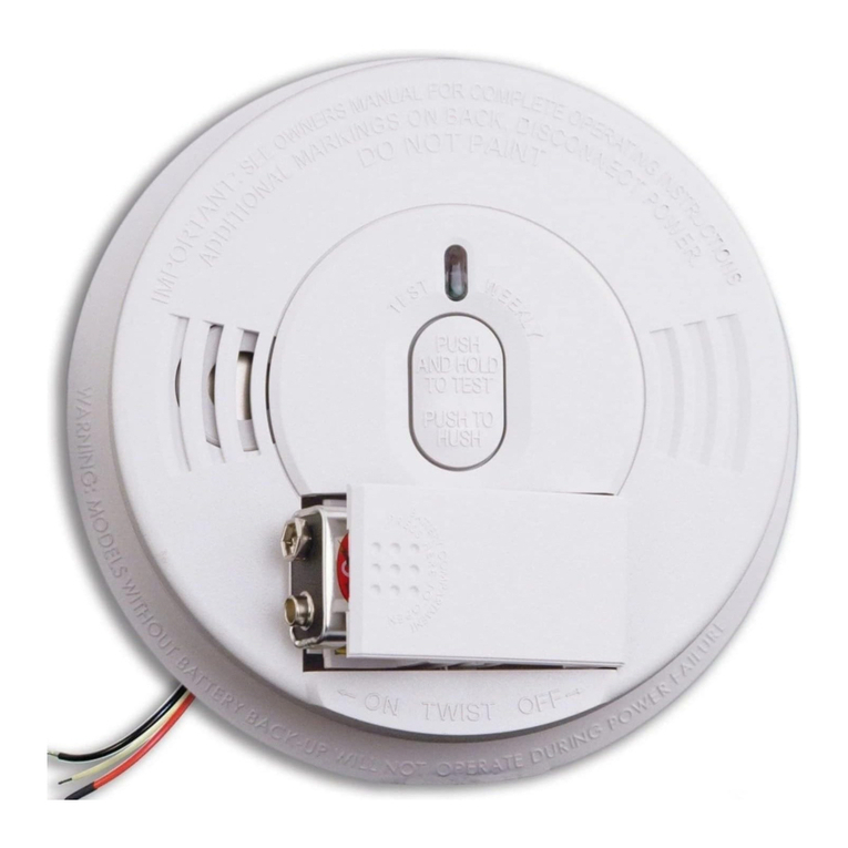
CAUTION! IF THE BATTERY REMINDER FINGER(S) ARE NOT HELD
DOWN IN THE BATTERY COMPARTMENT BY THE BATTERY, THE BATTERY
DOOR WILL NOT CLOSE, THE AC QUICK CONNECTOR WILL NOT ATTACH
TO THE ALARM, AND THE ALARM WILL NOT ATTACH TO THE TRIM RING
(SEE SECTION 6, FIGURE 9).
FUSE OR CIRCUIT BREAKER
RED
BLACK
WHITE
BLACK
WHITE
RED
CONNECTOR CONNECTOR
Kidde
Relay Module
SM120X
First
Alarm
Additional
Alarm Optional
Accessory Additional
Alarm
1220-7208-02_EN_V2a.qxd:_ 2015.12.4 10:19 AM Page 6

