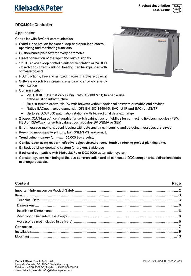
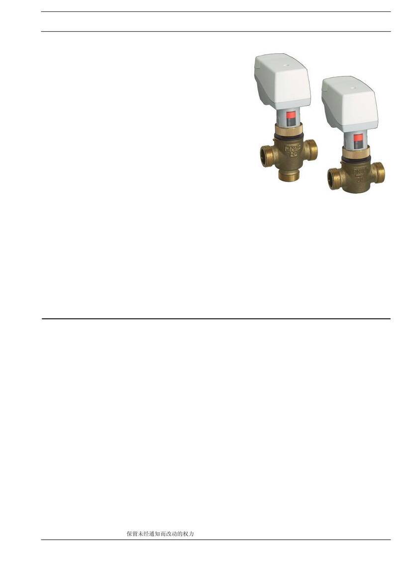
Kieback&Peter FBR5 User manual

Kieback&Peter GmbH & Co. KG
Tempelhofer Weg 50, 12347 Berlin/Germany
Telefon: +49 30 60095-0, Telefax: +49 30 60095-164
www.kieback-peter.de, [email protected]
Datasheet 2.50-60.003-01-EN
FBR3
Issue 2016-01-05
A
Änderungen vorbehalten - Contents subject to change - Sous réserve de modifications - Reservado el derecho a modificación - Wijzigingen
voorbehouden - Con riserva di modifiche - Innehåll som skall ändras - Změny vyhrazeny - Zmiany zastrzeżone - Возможны изменения -
A változtatások jogát fenntartjuk - ֱ⬭㒣䗮ⶹ㗠ᬍࡼⱘᴗ
Product Description
FBR3 Room Controller
Application
The FBR5 Rom Controller are used within the DDC3000
and DDC4000 automation systems for individual room
control.
With 2 continuous output signals DC 0 V to 10 V for
sequential control.
The fieldbus is used for data communication with the
DDC3xxx/DDC4xxx controller.
DDC software menus, such as optimize/heating; limiting
value and Y Set, can extend the basic closed loop control
function.
Content Page
Important Information Regarding Product Safety ..................................................................................................2
Item........................................................................................................................................................................3
Technical Data.....................................................................................................................................................3
Accessories (not included in delivery) .................................................................................................................3
Dimensions..........................................................................................................................................................4
Connection...........................................................................................................................................................4
Mounting and Installation.......................................................................................................................................5
Setting the Fieldbus Address.................................................................................................................................6
self-control program...............................................................................................................................................6
Bridging program ...................................................................................................................................................6

APage 2 / 6
Product DescriptionFBR3
Datasheet 2.50-60.003-01-EN Issue 2016-01-05
Important Information Regarding Product Safety
Safety Instructions
This data sheet contains information on installing and commissioning the product "FBR3". Each
person who carries out work on this product must have read and understood this data sheet. If you
have any questions that are not resolved by this data sheet, you can obtain further information from
the supplier or manufacturer.
If the product is not used in accordance with this data sheet, the protection provided will be impaired.
Applicable regulations must be observed when installing and using the device. Within the EU, these
include regulations regarding occupational safety and accident prevention as well as those from the
VDE (Association for Electrical, Electronic & Information Technologies). If the device is used in other
countries, it is the responsibility of the system installer or operator to comply with local regulations.
Mounting, installation and commissioning work on the devices may only be carried out by qualified
technicians. Qualified technicians are persons who are familiar with the described product and who
can assess given tasks and recognize possible dangers due to technical training, knowledge and
experience as well as knowledge of the appropriate regulations.
Legend
WARNING
Indicates a hazard of medium risk which can result in death or severe bodily injury if it is not avoided.
CAUTION
Indicates a hazard of low risk which can result in minor or medium bodily injury if it is not avoided.
!CAUTION
Indicates a hazard of medium risk which can result in material damage or malfunctions if it is not
avoided.
NOTE
Indicates additional information that can simplify the work with the product for you.
Notes on Disposal
For disposal, the product is considered waste from electrical and electronic equipment (electronic
waste) and must not be disposed of as household waste. Special treatment for specific components
may be legally binding or ecologically sensible. The local and currently applicable legislation must be
observed.

A
Page 3 / 6
Datasheet 2.50-60.003-01-EN
FBR3Product Description
Issue 2016-01-05
Item
Technical Data
Accessories (not included in delivery)
FBR3 Fieldbus loop controller for individual room control with 2 continuous output signals
DC 0 V to 10 V.
Nominal voltage DC 12 V ±20%; 1,6 W
Inputs Room sensor with KP10 measuring system (2.73 V at 0 °C; TC = 10 mV/K)
Remote adjuster for setpoint correction (10 k)
3 digital inputs for voltage-free contacts, configurable for program time
extension, presence detector, window contact, fault message, operating
message, etc.
Outputs 2 continuous outputs DC 0 to 10 V, max. 5 mA
1 “Plant On” relay output; voltage-free changeover switch AC 230 V;
8 (3) A
1 transistor output for LED display; DC 12 V, 2 mA
Bus connection Fieldbus, max. 2000 m
Address switch Addressing 01–63 by means of 2 rotary switches in the housing
Displays 2 LEDs LED data: flashes during fieldbus data transmission
LED error: lights up in case of fieldbus error
Housing Plastic housing, cover color RAL 9010 (pure white)
Installation Mounted on wall or on flush-mounted box
Degree of protection IP20
Protection class II in accordance with EN 60730
Ambient temperature 0 to 45°C
Ambient humidity 20.. 80 % r.h., non-condensing
Weight 0.60 kg
Dimensions WxHxD mm 154x83.4x35
Z19 Standard rail bracket clip
For mounting on TH35-7.5 top hat rail

APage 4 / 6
Product DescriptionFBR3
Datasheet 2.50-60.003-01-EN Issue 2016-01-05
Dimensions
Connection
205,0
110,0
15,0
39,0
4
5
6
7
8
9
10
11
14
15
16
21
23
24
25
26
27
28
29
30
31
32
33
K1
K2
K3
K4
230V AC
8(3)A
V 1 Y
V1Y
0 V AC/DC
Y2 = 0..10 VDC
24 V AC Y1 = 0..10 VDC
K5
0 V
12 V DC
12 VDC
+
CAN +
-
CAN -
ϑ
KP10
10KΩ
3
2
1
LED
12 V/ 2 mA
FBR3
M
M
29
30
31
32
12 VDC
+
-
FBR3
20
19
18
17
DDC3000
29
30
31
32
12 VDC
+
-
FBR3
20
19
18
DDC4000
40
39
38
DDC4000
CAN1
CAN2

A
Page 5 / 6
Datasheet 2.50-60.003-01-EN
FBR3Product Description
Issue 2016-01-05
Mounting and Installation
WARNING
Contact with live parts of electrical domestic installation can cause death due to electric shock.
Mounting/removal may only be carried out when power is switched off.
Wall mounting
Flush mounting
1 2 3 4
3,5x 35
5 6 7
01..63
8
910
1 2 3 4
01..63
5 6

APage 6 / 6
Product DescriptionFBR3
Datasheet 2.50-60.003-01-EN Issue 2016-01-05
■Lines for the power supply and fieldbus should be laid together in one shielded cable, cable type
at least 0.8 mm in diameter, with the wires twisted together in pairs. Here, one twisted pair of wires
is to be used for the power supply and another for the fieldbus (see wiring diagram).
■At the end of the fieldbus (furthest point from the DDC controller, max. 2000 m), the two connection
lines must be fitted with a terminating resistor of about 180 (terminating resistor is included with
the DDC controller).
Setting the Fieldbus Address
The rotary switches for setting the fieldbus are
located inside the cover. Information on opening
and closing the device can be found in the chapter
"Mounting and Installation", page 5.
Set the first rotary switch to the first digit of the
fieldbus address, the second rotary switch to the
second digit.
The example shows the address 15.
Permitted range for the fieldbus address: 01 to 63
After setting the address to 00 and switching on
the power, the FBR3 functions in the self-control
program. (See chapter “self-control program.”,
page 6.)
self-control program.
Use without a controller is possible. The self-control program is then responsible for the control
functions of the FBR3. To use the self-control program, set the fieldbus address to “00” (See
chapter “Setting the Fieldbus Address”, page 6.).
Use of the self-control program is indicated by the flashing red external LED.
In the self-control program, the FBR3 regulates the system to a setpoint of a 15 °C night setpoint or
20 °C day setpoint as a constant P loop controller.
The closed loop control function affects the heating (output Y1) and cooling (output Y2) sequences.
The contact K2 is used to switch between the night setpoint and day setpoint.
K2 open = night setpoint 15 °C
K2 closed = day setpoint 20 °C
NOTE
The setting knob is not supported in the self-control program.
Further information can be found in the project planning documentation.
Bridging program
If communication with the automation station is interrupted, the FBR3 continues to work with the
current parameterization in the bridging program.
Use of the bridging program is indicated by the illuminated red external LED.
19
36
1
18
01
2
3
4
5
6
7
8
9
01
2
3
4
5
6
× 10 × 1

Table of contents
Other Kieback&Peter Controllers manuals

Kieback&Peter
Kieback&Peter BMR410 Technical specifications

Kieback&Peter
Kieback&Peter MD15/230-HR Technical specifications

Kieback&Peter
Kieback&Peter MD15-FTL-HE User manual

Kieback&Peter
Kieback&Peter MD15-FTL-902 User manual

Kieback&Peter
Kieback&Peter DDC4200e User manual

Kieback&Peter
Kieback&Peter MD15/230 Technical specifications

Kieback&Peter
Kieback&Peter MD15-FTL-315 User manual

Kieback&Peter
Kieback&Peter DDC4400e Technical specifications

Kieback&Peter
Kieback&Peter MD15-R-HE Technical specifications

Kieback&Peter
Kieback&Peter MD15-HR User manual