Kieback&Peter DCS2501 Technical specifications

Kieback&Peter GmbH & Co. KG
Tempelhofer Weg 50, 12347 Berlin/Germany
Telefon: +49 30 60095-0, Telefax: +49 30 60095-164
www.kieback-peter.de, [email protected]
Datasheet 2.50-12.501-01-EN
DCS2501
Issue 2014-05-20
A
Änderungen vorbehalten - Contents subject to change - Sous réserve de modifications - Reservado el derecho a modificación - Wijzigingen
voorbehouden - Con riserva di modifiche - Innehåll som skall ändras - Změny vyhrazeny - Zmiany zastrzeżone - Возможны изменения -
A változtatások jogát fenntartjuk - ֱ⬭㒣䗮ⶹ㗠ᬍࡼⱘᴗ
Product Description
DCS2501 Gateway (Internet)
Application
The DCS2501 is an Ethernet gateway in System 3000. It allows you to
connect to a remote BMS via the Internet.
The DCS2501 features a P90 interface for direct communication with a
DDC3000, an HRP or an LRP.
The DCS2501 enables you to replace an existing modem connection
with an Internet connection.
Content Page
Important Information Regarding Product Safety ..................................................................................................2
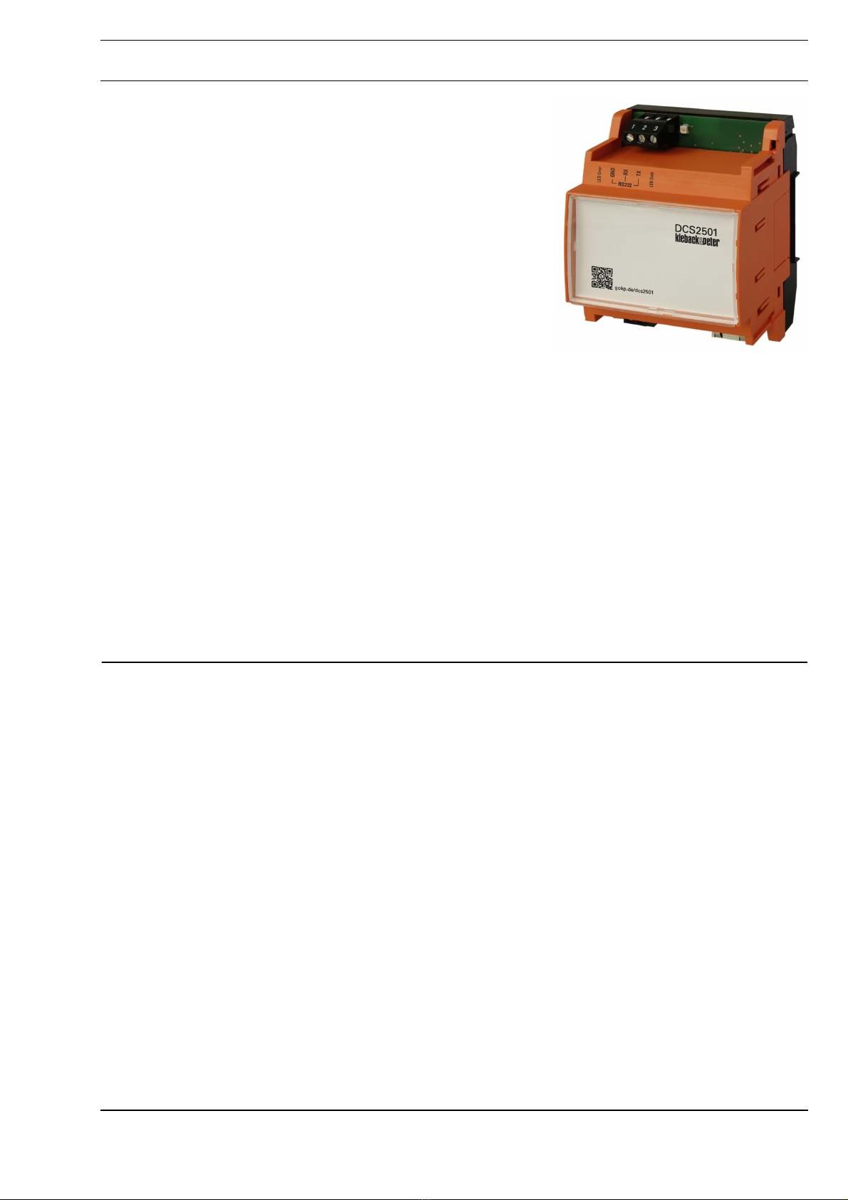
Item........................................................................................................................................................................3
Technical Data.....................................................................................................................................................3
Compatibility ........................................................................................................................................................3
Dimensions..........................................................................................................................................................3
Connection...........................................................................................................................................................4
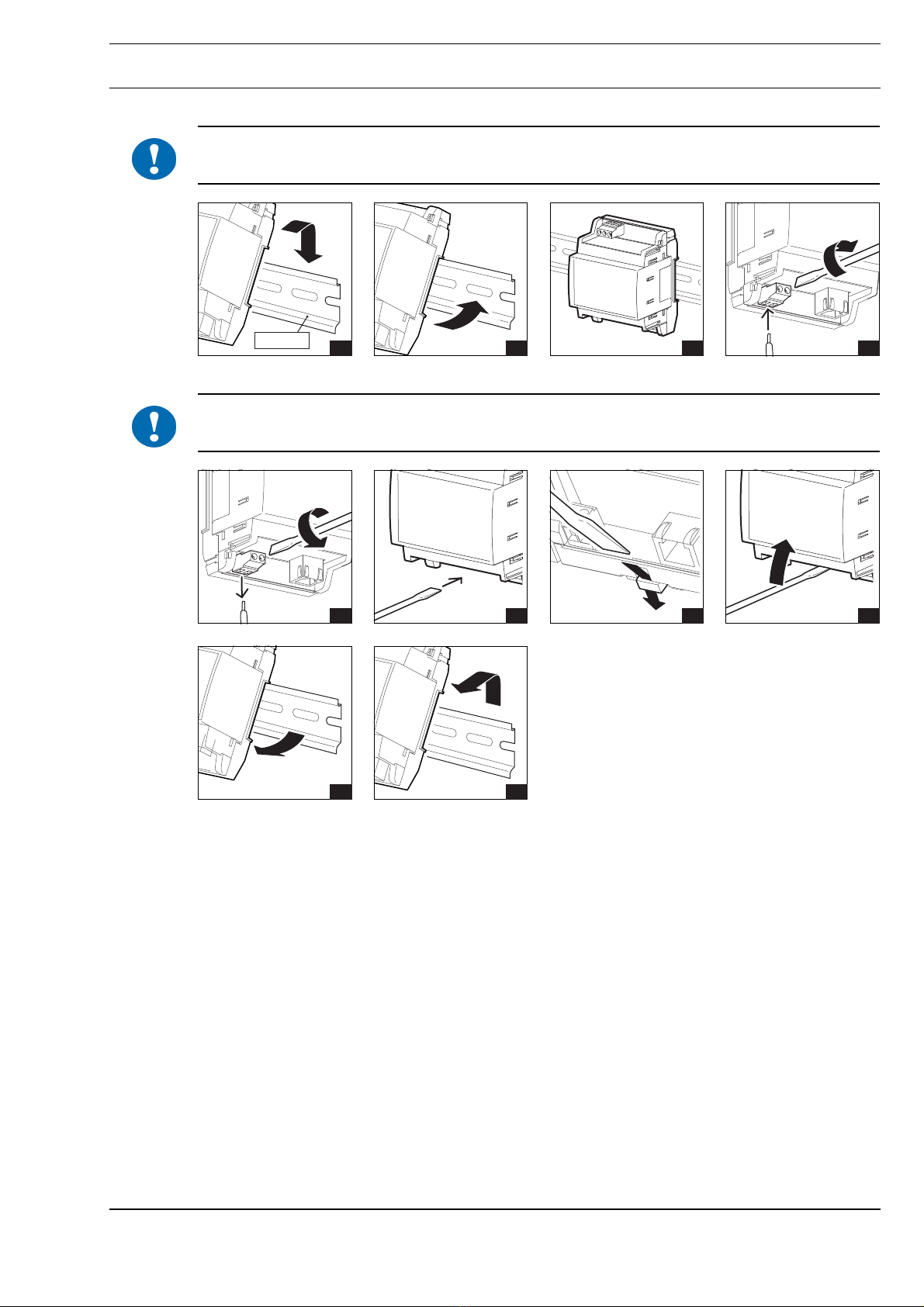
Mounting ................................................................................................................................................................5
Removal.................................................................................................................................................................5
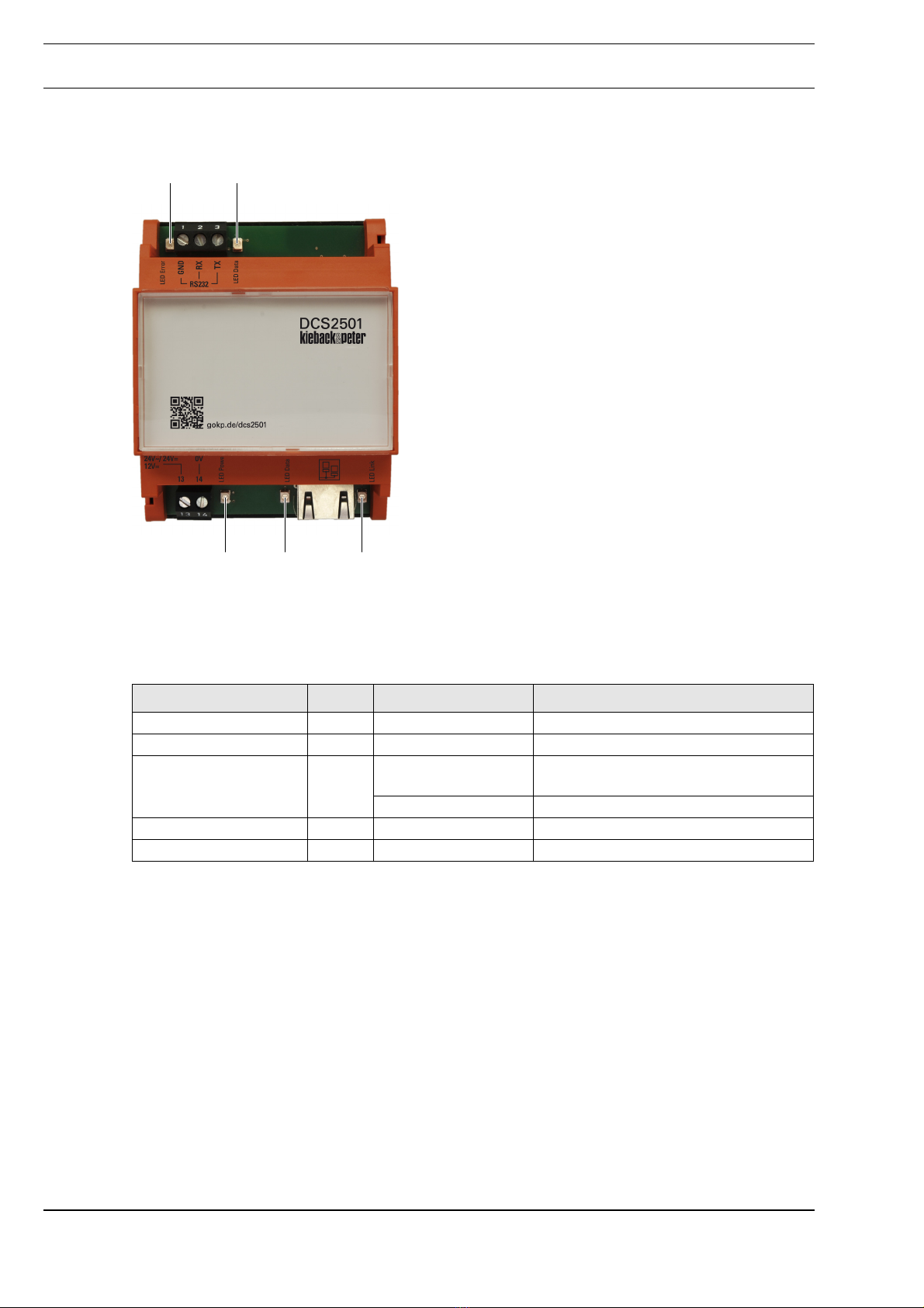
Indicators and Controls..........................................................................................................................................6
LEDs....................................................................................................................................................................6
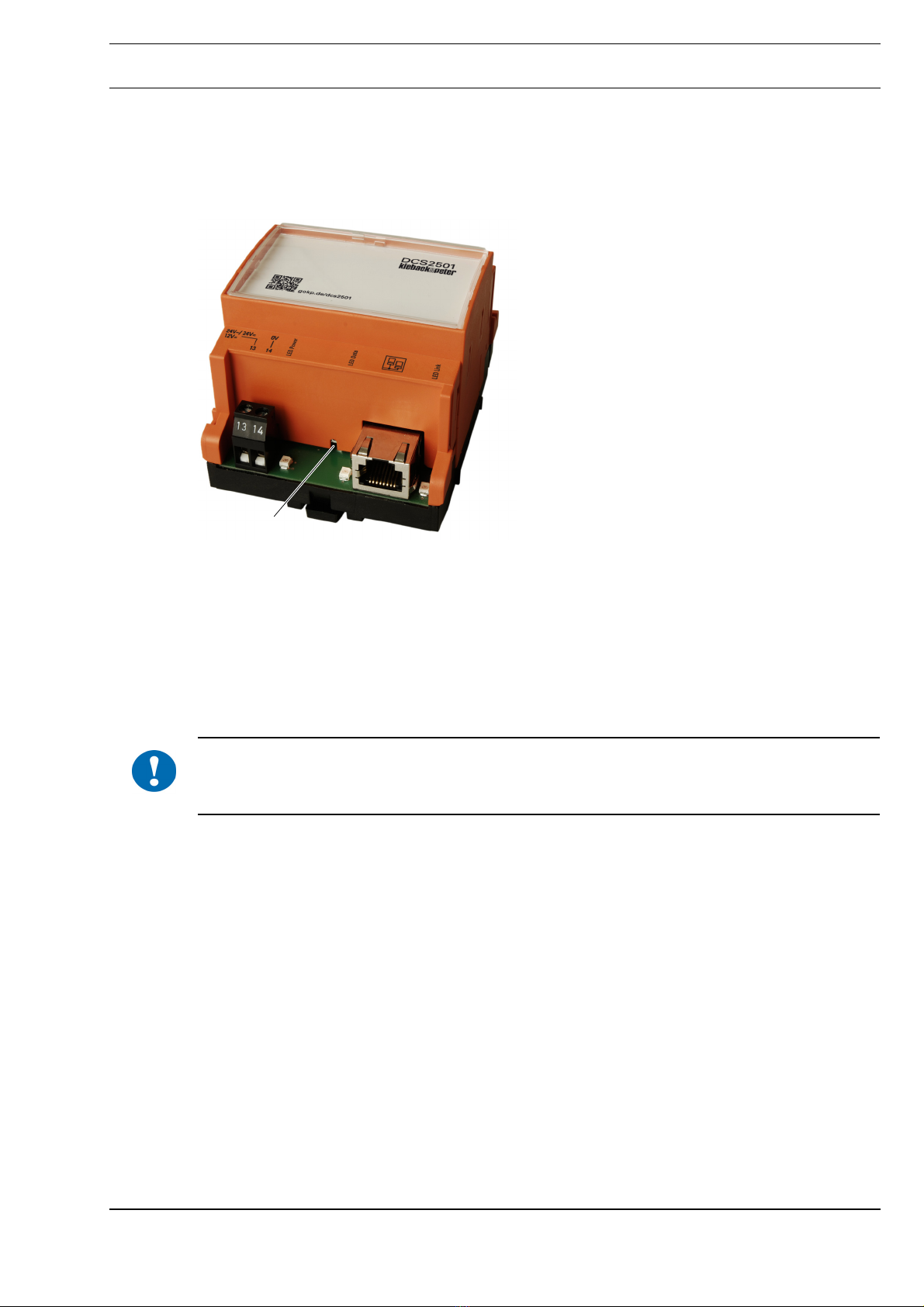
Reset button ........................................................................................................................................................7
Commissioning ......................................................................................................................................................8
Configuring the DCS2501....................................................................................................................................9
Configuring the controller...................................................................................................................................11
Configuring the BMS..........................................................................................................................................12
Preparation ..........................................................................................................................................................13

APage 2 / 14
Product DescriptionDCS2501
Datasheet 2.50-12.501-01-EN Issue 2014-05-20
Important Information Regarding Product Safety
Safety Instructions
This data sheet contains information on installing and commissioning the product "DCS2501". Each
person who carries out work on this product must have read and understood this data sheet. If you
have any questions that are not resolved by this data sheet, you can obtain further information from
the supplier or manufacturer.
If the product is not used in accordance with this data sheet, the protection provided will be impaired.
Applicable regulations must be observed when installing and using the device. Within the EU, these
include regulations regarding occupational safety and accident prevention as well as those from the
VDE (Association for Electrical, Electronic & Information Technologies). If the device is used in other
countries, it is the responsibility of the system installer or operator to comply with local regulations.
Mounting, installation and commissioning work on the devices may only be carried out by qualified
technicians. Qualified technicians are persons who are familiar with the described product and who
can assess given tasks and recognize possible dangers due to technical training, knowledge and
experience as well as knowledge of the appropriate regulations.
Legend
WARNING
Indicates a hazard of medium risk which can result in death or severe bodily injury if it is not avoided.
CAUTION
Indicates a hazard of low risk which can result in minor or medium bodily injury if it is not avoided.
!NOTICE
Indicates a hazard of medium risk which can result in material damage or malfunctions if it is not
avoided.
NOTE
Indicates additional information that can simplify the work with the product for you.
Notes on Disposal
For disposal, the product is considered waste from electrical and electronic equipment (electronic
waste) and must not be disposed of as household waste. Special treatment for specific components
may be legally binding or ecologically sensible. The local and currently applicable legislation must be
observed.

A
Page 3 / 14
Datasheet 2.50-12.501-01-EN
DCS2501Product Description
Issue 2014-05-20
Item
Technical Data
Compatibility
The DCS2501 is compatible with BMS version 9.13 or higher. Lower BMS versions are not supported.
DCS2501 Gateway (Internet)
Nominal voltage 12 V DC ± 10 %; 1.6 W
Or
24 V DC ± 10 %; 1.6 W
Or
24 V AC ± 20 %; 50..60 Hz; 3.6 VA
Indicators and Controls LEDs for bus operation and indicating errors
■1 LED for supply voltage
■2 LEDs Ethernet
■2 LEDs for P90
Reset button
Interfaces P90: Screw terminal, RS232
Ethernet: RJ45 sokket, 100BASE-T / 10BASE-T
Housing Base: Plastic (PC); black
Hood: Plastic (PBT); orange (RAL 2009)
Overvoltage category III
Rated impulse voltage 800 V
Level of contamination 2
How It Works
Protection class
Degree of protection
Ambient temperature
Ambient humidity
Type 1
III
IP20
0..50 °C
During operation: 20% to 80% r.h.; non-condensing
Out of operation: 5% to 90% r.h.; non-condensing
Installation Standard rail TH 35-7.5 in closed housing
CE conformity 89/336/EWG electromagnetic compatibility
73/23/EWG Low Voltage Directive
Weight 130 g
Dimensions WxHxD mm 71.8 x 90 x 60, 4 horizontal pitches

APage 4 / 14
Product DescriptionDCS2501
Datasheet 2.50-12.501-01-EN Issue 2014-05-20
Dimensions
Connection
P90
P90 uses RS232 as its bus. RS232 is specified in ANSI EIA/TIA-232-F.
To connect the RS232 bus, use a shielded pair of wires for the data lines (RX and TX) and an
additional wire for signal ground (GND).
The maximum cable length for RS232 is 15 m for standard cables, e.g. JY(ST)Y cables with
100 pF/m. If you need to cover larger distances, use a cable with a low capacity. A cable with half the
capacity has twice the maximum length.
Example calculation: A Cat7 cable with 40 pF/m allows a length of 15 m • 100 pF / 40 pF = 37.5 m
71,8
0,09
60,0
44,7
13 14
0V
321
RJ45
Ethernet
RS232
GND
RX
TX
24V~
24V=
12V=
12V=
24V=
0V
24V~
321
RS232
GND
RX
TX
GND
TX
RX
DDC3010
DDC3100
DDC3035
302931
GND
TX
RX
DDC3002
DDC3003
DDC3200
DDC3300
595860
321
RS232
GND
RX
TX
GND
TX
RX
HRP/LRP
313233

A
Page 5 / 14
Datasheet 2.50-12.501-01-EN
DCS2501Product Description
Issue 2014-05-20
Mounting
!NOTICE
Mount or remove only when power is switched off.
Removal
!NOTICE
Mount or remove only when power is switched off.
EN 50022 1 2 3 4
1 2 3 4
5 6

APage 6 / 14
Product DescriptionDCS2501
Datasheet 2.50-12.501-01-EN Issue 2014-05-20
Indicators and Controls
LEDs
1 LED RS232: Error
2 LED RS232: Data
3 LED Power
4 LED Ethernet Data
5 LED Ethernet Link
LED Color Signal Meaning
"LED RS232: Error" (1) Red Remain lit No P90 connection
"LED RS232: Data" (2) Green Flickering Data being transferred
"LED Power" (3) Green Flashing Device is starting/running a firmware
update
Remain lit Device is ready
"LED Ethernet Data" (4) Yellow Flickering Data being transferred
"LED Ethernet Link" (5) Green Remain lit Connection OK
12
34 5

A
Page 7 / 14
Datasheet 2.50-12.501-01-EN
DCS2501Product Description
Issue 2014-05-20
Reset button
Pressing the reset button can either restore the device to its initial state or restart the DCS2501.
Briefly pressing the reset button restarts the DCS2501. The settings of the DCS2501 are maintained.
Pressing the reset button for at least 3 seconds performs a reset. All settings are deleted and the
initial state is restored.
1 Reset button
Restart
►Ziehen Sie den Ethernet-Stecker vom Gerät ab.
Dadurch werden Störungen des Netzwerks vermieden.
►Drücken Sie kurzzeitig den Reset-Taster im Loch (z. B. mit einer Büroklammer).
Es wird ein Neustart durchgeführt.
Reset
!NOTICE
Pressing the reset button for longer deletes all the DCS2501’s settings and restores it to its initial
state.
►Disconnect the Ethernet connector from the device.
This prevents the network from being disrupted.
►Press the recessed reset button for at least 3 seconds (e.g. with a paper clip).
The device is reset. The device is restored to its initial state.
1

APage 8 / 14
Product DescriptionDCS2501
Datasheet 2.50-12.501-01-EN Issue 2014-05-20
Commissioning
Information for the network administrator
If the DCS2501 and the BMS communicate via the Internet, the DCS2501 requires a public IP
address at which it can be reached by the BMS.
The DCS2501and the BMS can also communicate via NAT if port forwarding is activated for all ports.
VPN can also be used, e.g. via the Kieback&Peter technoWay.
The bandwidth required for DCS2501 is less than 200 kbit/s.
The network’s “ping” response time must be less than 200 ms.
The network’s maximum downtime must be less than 20 ms.
The standard Ethernet MTU should be 1500 bytes. DSL routers often use a smaller MTU. If this is
the case, the Ethernet packets from the DCS2501 and the BMS are sent in fragmented form.
Adjusting the router’s MTU improves the performance.
If the IP address is assigned via DHCP, the BMS must have a fixed IP address. This fixed IP address
will be provided to the Kieback&Peter representative setting up the BMS.
The following ports on the DCS2501 must be accessible from the BMS:
■Port 22 (SSH):
For encrypted data communication with the BMS.
■Port 23 (SSH/Telnet):
For low-level analysis of the device by Kieback&Peter Support (optional).
■Port 80 (HTTP):
For configuring the DCS2501 via the implemented web server (optional).
■Port 19280 (DDC/IPC):
For configuring the IP address. The IP address can be configured using an XML frame sent as a
broadcast (optional).

A
Page 9 / 14
Datasheet 2.50-12.501-01-EN
DCS2501Product Description
Issue 2014-05-20
Configuring the DCS2501
►Connect the DCS2501 to your computer with an Ethernet cable. It doesn’t matter whether you
use a crossover or a non-crossover cable; the DCS2501 automatically identifies the cable.
►Ensure that the DCS2501 and your computer are connected to the power supply and turned on.
►Open a web browser on the computer and call up the IP address of the DCS2501. In the default
settings:
http://192.168.1.1
►Select a language by clicking on a flag below the menus in the web interface.
The configuration is available in German and English.
Log on to the DCS2501
►Select the Logon/Logoff menu.
►Select User 3.
►Enter the password.
Rights concept
■User 1
– Users are automatically User 1 when the DCS2501’s web server is called up.
Or
After every logoff through the Logon/Logoff menu.
– User 1 can only view the settings on the DCS2501, not change them.
■User 3
– Password: "2460"
– User 3 can: Change IP and DCS settings, run updates.
■User 4 (all rights)
– Only available for developers from Kieback&Peter.

APage 10 / 14
Product DescriptionDCS2501
Datasheet 2.50-12.501-01-EN Issue 2014-05-20
Enter the settings
►Enter the information from the table "Planning template DCS2501", on page 13.
►Enter the network setting information:
►Click the “Save” button.
A message appears saying the settings will not be applied until the next time the device is
restarted.
►Enter the device setting information:
NOTE
For configuration via NAT, the WAN IP address of the BMS’s router must be used in the device
settings of the DCS2501.
For configuration via NAT, the WAN IP address of the DCS2501’s router must be used in the device
settings of the BMS.

A
Page 11 / 14
Datasheet 2.50-12.501-01-EN
DCS2501Product Description
Issue 2014-05-20
Operating mode
The following settings can be chosen as the operating mode:
■BMS active
– BMS active means that the BMS establishes the connection to the DCS2501.
– The DCS2501requires a fixed IP address.
■DCS aktive
– DCS active means that the DCS2501 establishes the connection to the BMS.
– The BMS requires a fixed IP address.
■Deactivated
– The DCS2501 is not integrated into the network (not active).
►Click the “Save” button.
A message appears saying the settings will not be applied until the next time the device is
restarted.
►Restart the device.
►To do so, click on “System restart” in the menu bar.
Configuring the controller
►Configure the following parameters in the DDC3000:
NOTE
The parameter 2055/01 allows you to check the communication of the DDC3000 to the BMS via the
DCS2501.
Parameter Value
4599/01 = ON
4600/01 = Baud rate
See table "Planning template DCS2501", on page 13
2051/01 = DST mode
2031/01 = P90
The modem menu must be deactivated.

APage 12 / 14
Product DescriptionDCS2501
Datasheet 2.50-12.501-01-EN Issue 2014-05-20
Configuring the BMS
►Open the “Device configuration” menu on the BMS.
►Add a new device or change the existing device DCS2501.
►Enter the settings.
►See table "Planning template DCS2501", on page 13
NOTE
If multiple DCS2501s are used on one BMS, a unique DCS identification must be assigned to each
DCS2501.
A valid identification consists of max. 10 characters. Valid characters are A-Z, a-z or 0-9.
NOTE
For configuration via NAT, the routers’ IP address must be used.
Type: P90
Subtype: □LRP-HRP
□DDC3000
Connection: □DCS2501 - BMS active
□DCS2501 - DCS active
DCS identifica-
tion:
Example: “DDC3000”
Host: IP address of the DCS

A
Page 13 / 14
Datasheet 2.50-12.501-01-EN
DCS2501Product Description
Issue 2014-05-20
Preparation
You need the following information from the network administrator. Protocol the information in this
table:
Tab. 1: Planning template DCS2501
DCS2501 DCS ID
See
chapter “Configuring
the BMS”, page 12.
Operating mode
(connection):
See: Section Operat-
ing mode on page11
□BMS aktive
□DCS aktive
□Deactivated
IP configuration □Manual
□DHCP
- Manual IP address:
Network mask:
Gateway:
Host name:
DDC3000 / HRP /
LRP
Baud rate:
BMS IP address of the BMS:

APage 14 / 14
Product DescriptionDCS2501
Datasheet 2.50-12.501-01-EN Issue 2014-05-20
Table of contents
Other Kieback&Peter Gateway manuals