Kieback&Peter GmbH & Co. KG
Tempelhofer Weg 50, 12347 Berlin/Germany
Telefon: +49 30 60095-0, Telefax: +49 30 60095-164
www.kieback-peter.de, info@kieback-peter.com
Datasheet 2.50-40.132-01-EN
FBG132-FTL EnOcean System Gateway
Issue 2013-08-13
A
Änderungen vorbehalten - Contents subject to change - Sous réserve de modifications - Reservado el derecho a modificación - Wijzigingen
voorbehouden - Con riserva di modifiche - Innehåll som skall ändras - Změny vyhrazeny - Zmiany zastrzeżone - Возможны изменения -
A változtatások jogát fenntartjuk - 保留未经通知而改动的权力
Product Description
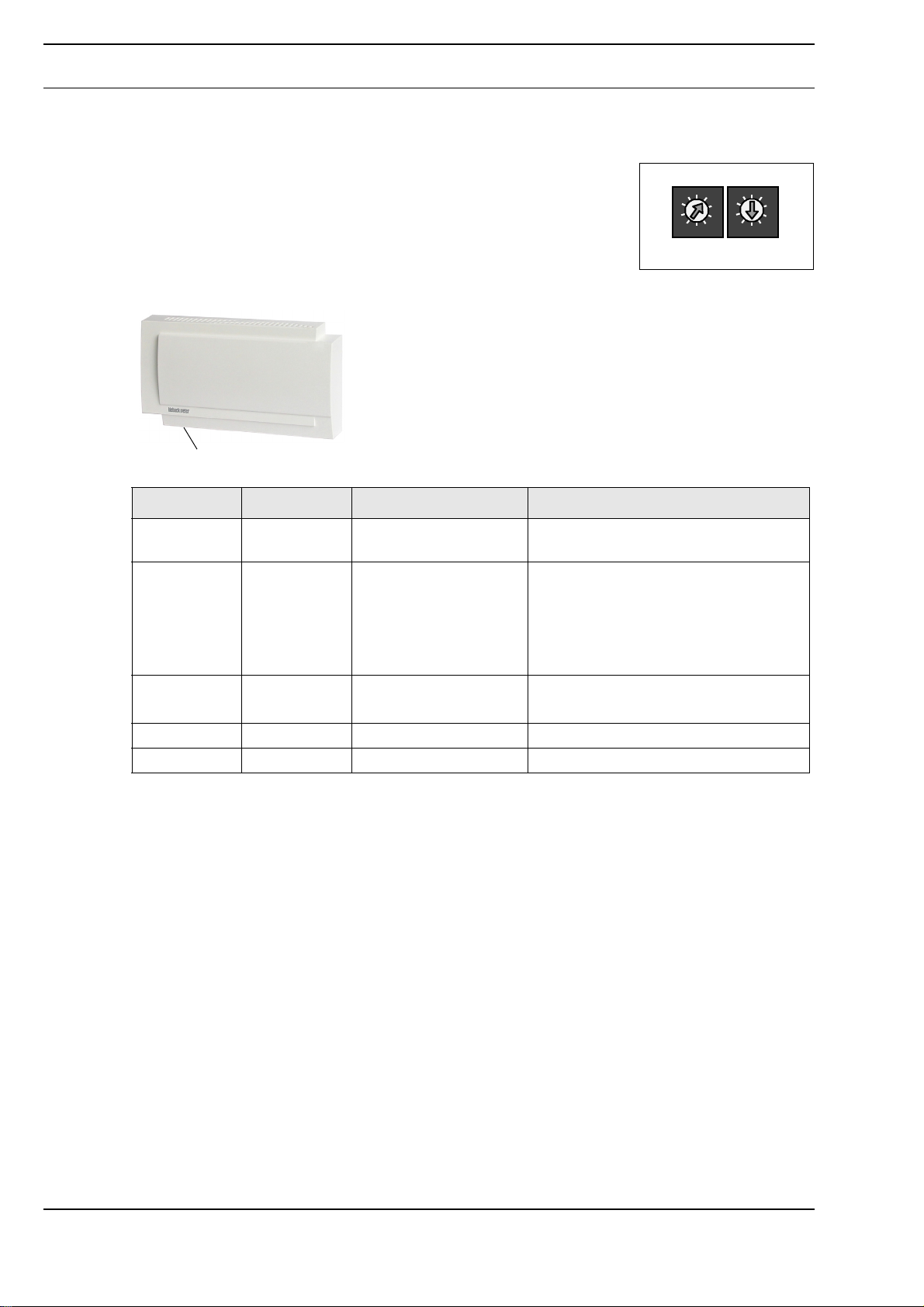
FBG132-FTL EnOcean System Gateway
Application
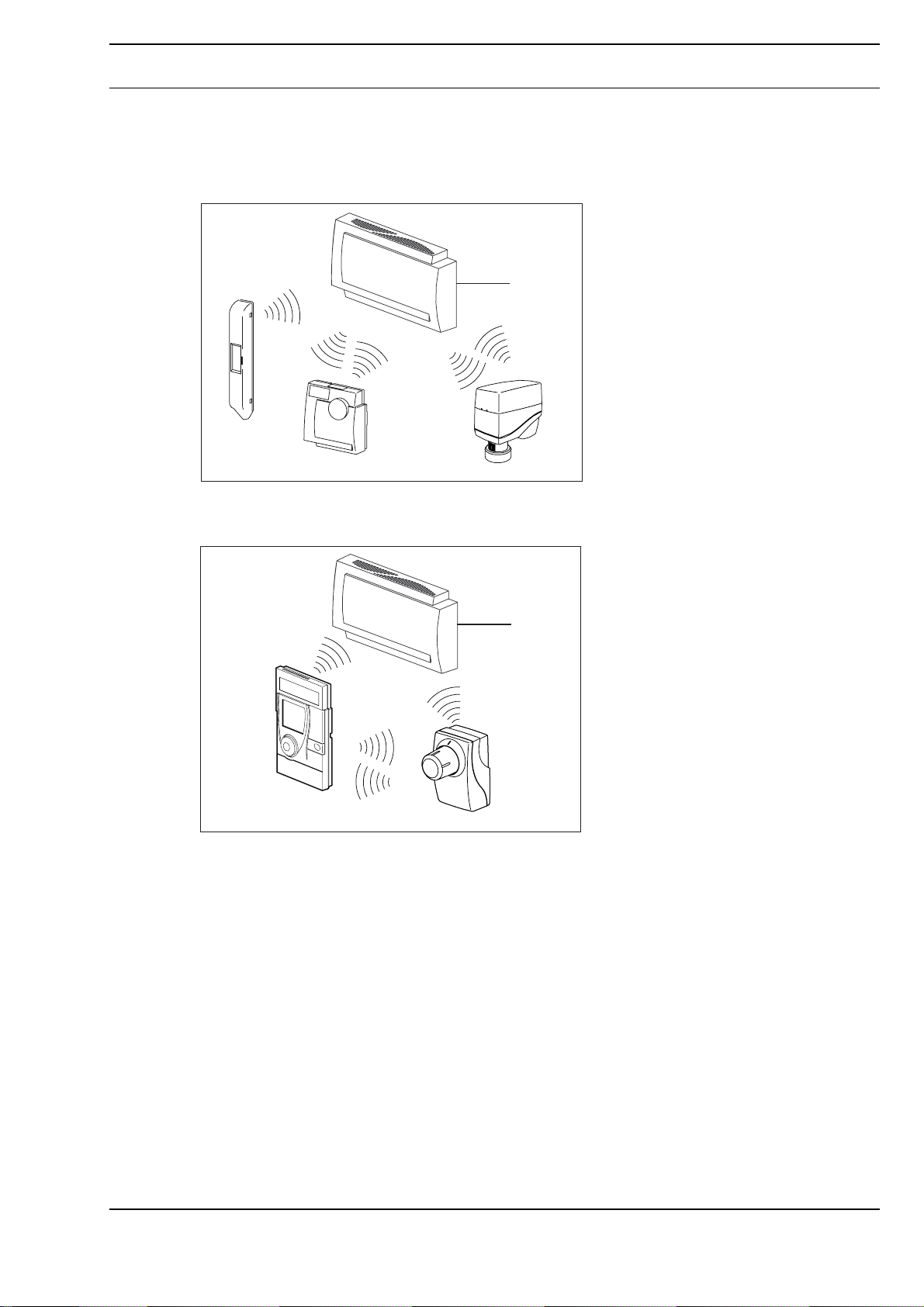
EnOcean system gateway for direct integration of up to 32
radio partners into the DDC4000 automation system for
building automation and control.
The system gateway supports the non-proprietary EnOcean
radio protocol.
It transmits the wireless data straight to the communication
structure of the DDC4000 automation system and the
building management system.
Content Page
Important Information Regarding Product Safety ..................................................................................................2
Item........................................................................................................................................................................3
Technical Data.....................................................................................................................................................3
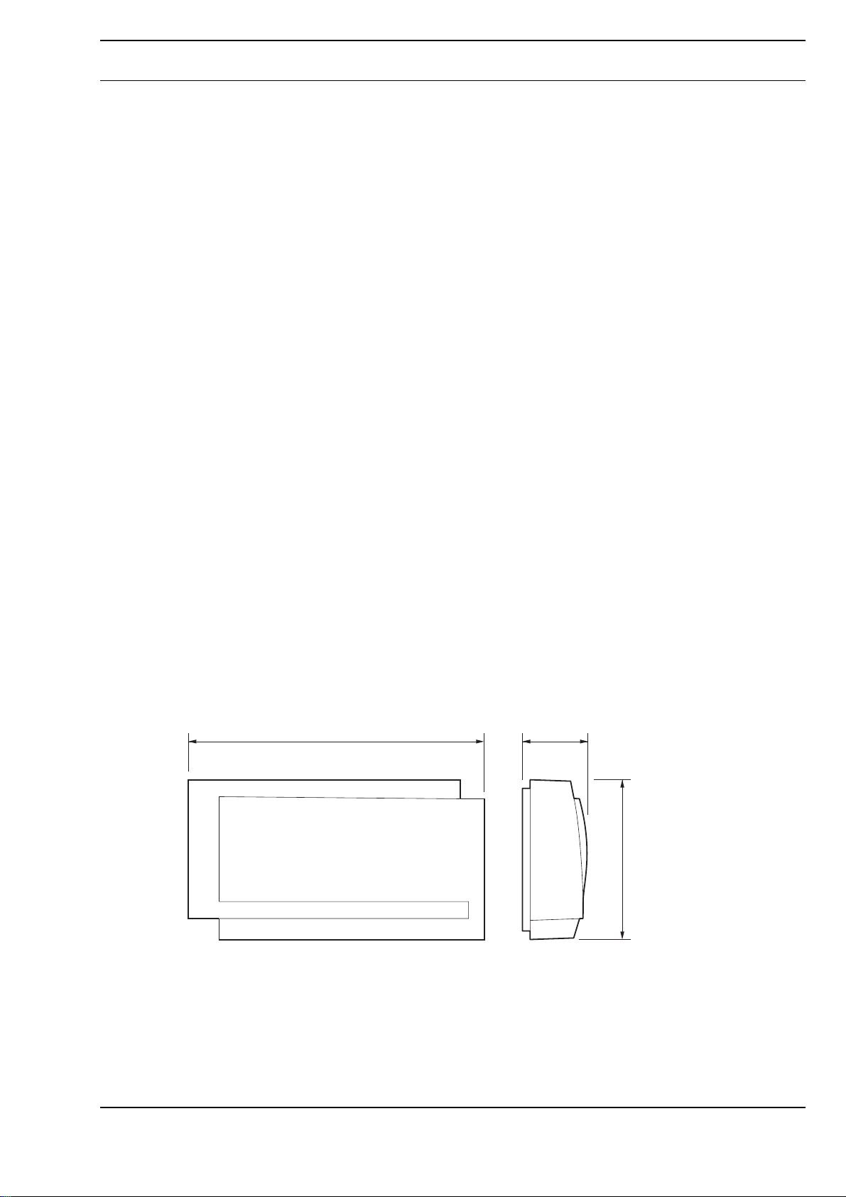
Dimensions..........................................................................................................................................................3
Connection...........................................................................................................................................................4
Wireless Interface ..................................................................................................................................................4
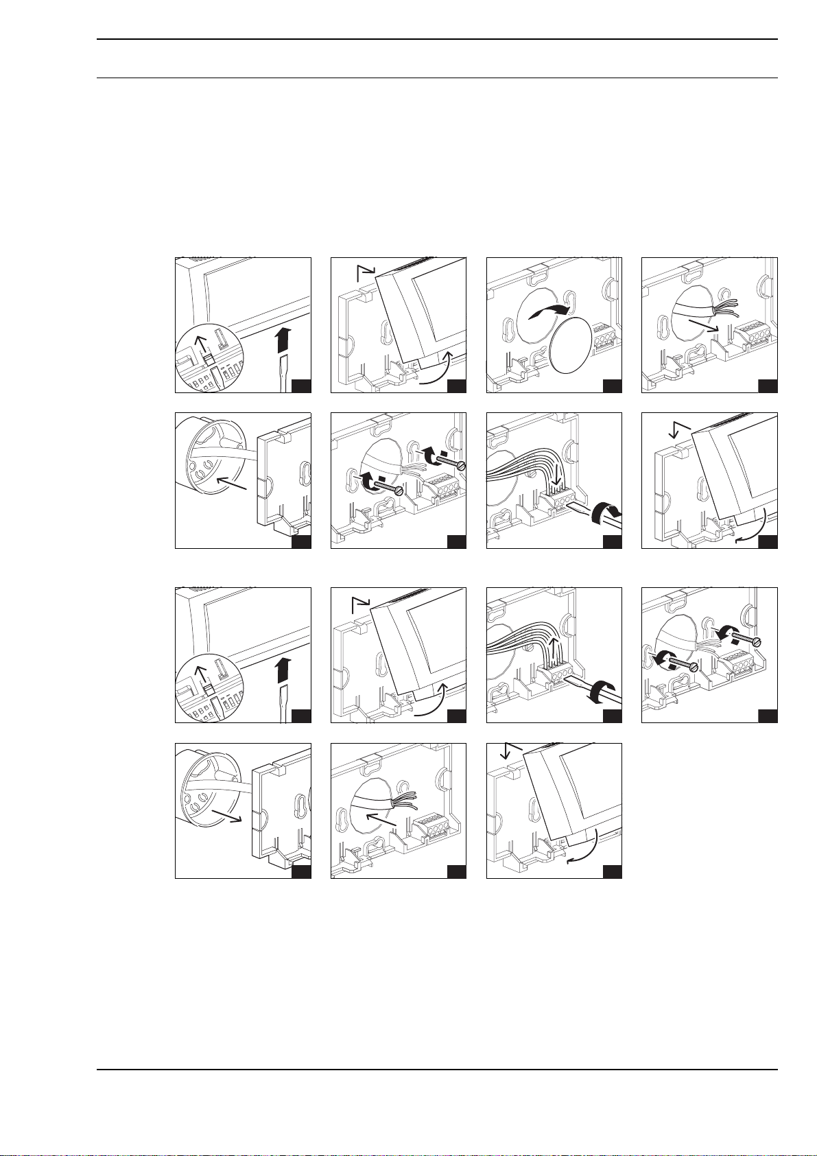
Installation..............................................................................................................................................................6
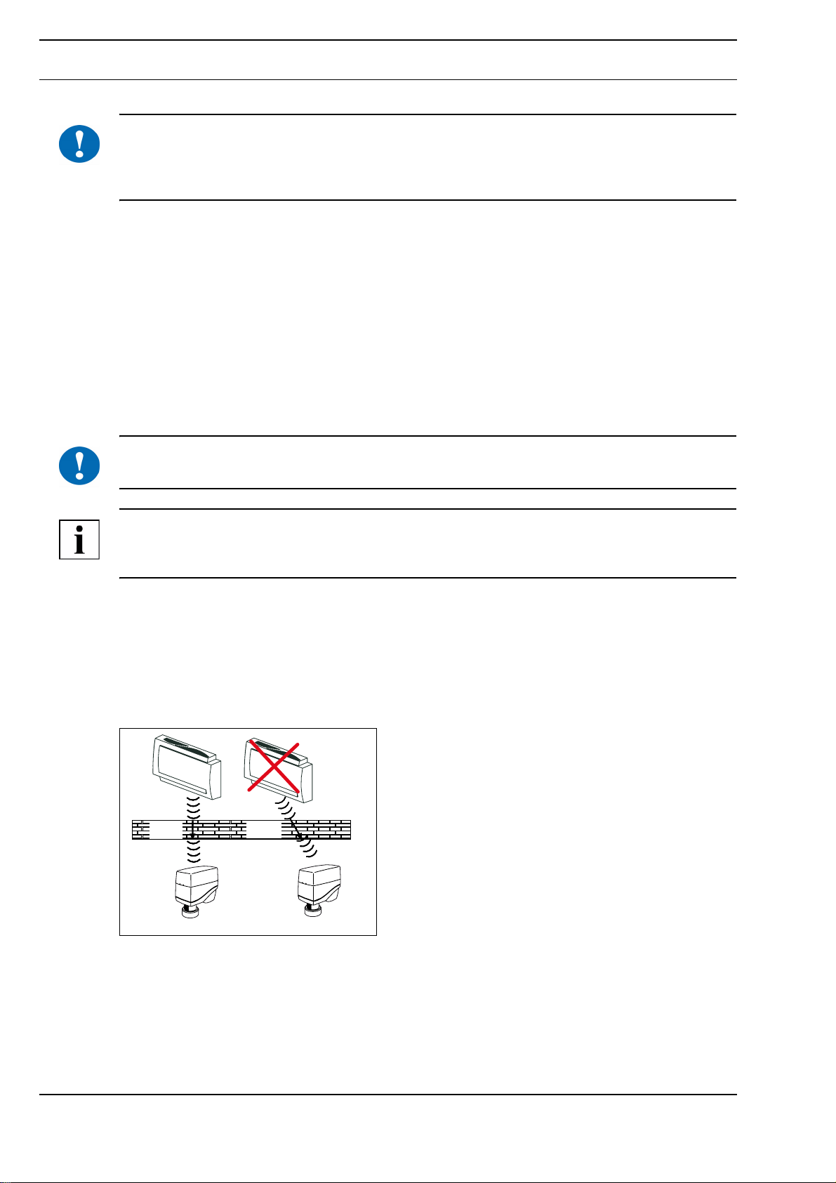
General radio installation instructions..................................................................................................................6
CAN bus installation notes...................................................................................................................................7
Mounting ................................................................................................................................................................7
Removal.................................................................................................................................................................7
Settings and LED displays.....................................................................................................................................8
Commissioning ......................................................................................................................................................9