Technical data sheet 1.15-10.002-01-en
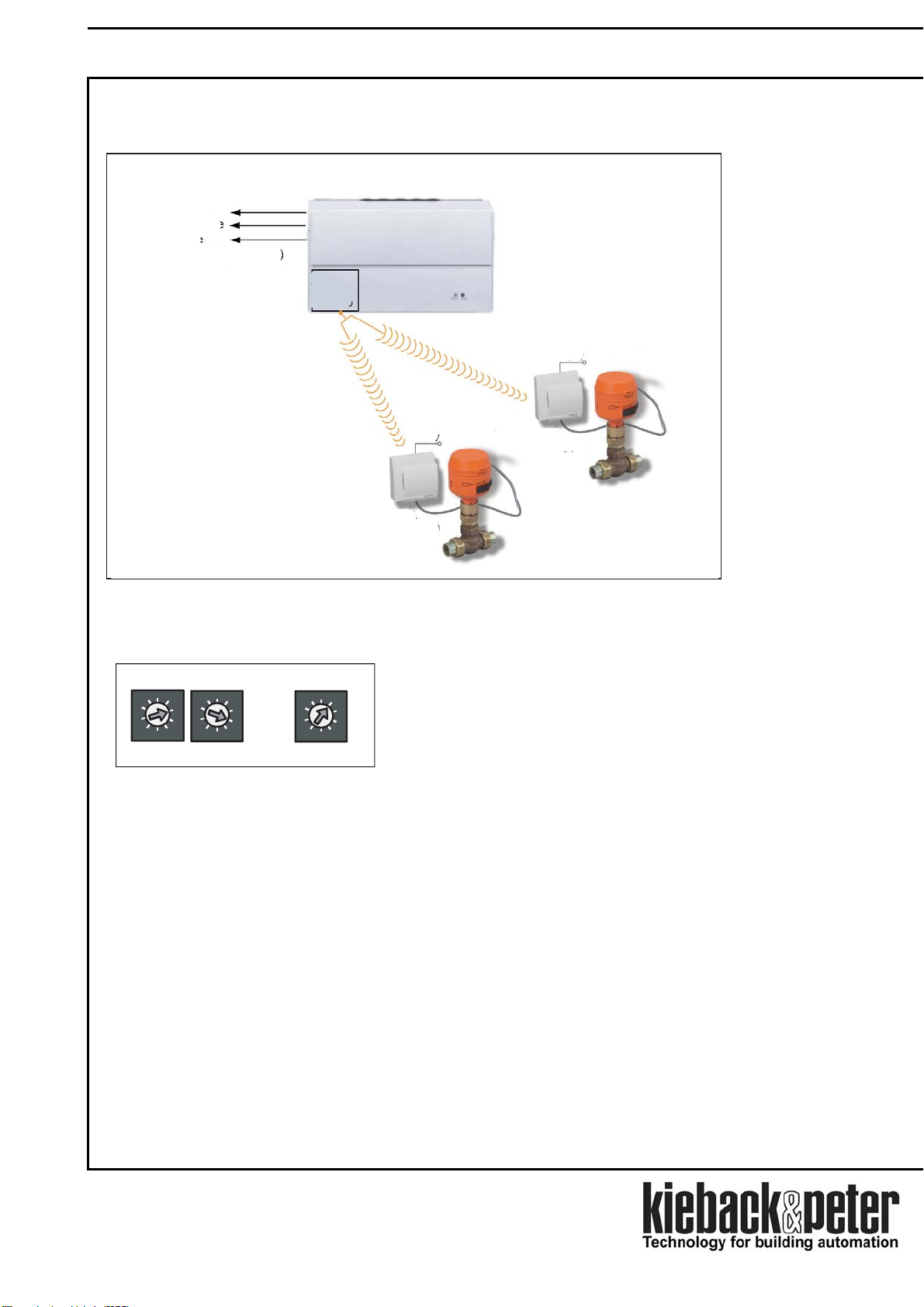
Multi radio connection MFA Device Description
Notes on the device description
The description contains instructions on using and assembling the Multi Radio Controller MFA.
In case of questions which cannot be clarified with this device description, please refer to the supplier or
manufacturer for further information.
The indicated installation instructions/regulations are valid in the Federal Republic of Germany.
When using the I/O components in other countries, the builder or operator of the plant is responsible for
compliance with the respective national regulations.
The operating staff is to be instructed in accordance with the description of the technical data sheet.
Safety Instructions
The currently valid worker’s occupational health regulations and regulations for the prevention of industrial
accidents must be observed when assembling and using the modules.
Any work concerning the installation or initial operation of the modules shall be exclusively carried out by qualified
specialists, see paragraph “Qualified specialists”.
Every person utilizing the devices shall have read and understood the descriptions in the technical data sheet.
Meaning of the symbols in the technical data sheet:
Warning of dangerous electrical voltage
Danger
General warning, strictly observe this notice
Warning
Further notice to observe
Note
Danger means mortal danger, severe bodily injuries or serious material damage in case of
non-observance.
Warning means danger of bodily injuries or material damage in case of non-observance.
Note indicates an information which is particularly stressed.
Qualified specialists
Qualified specialists for the purposes set out in this technical data sheet are persons who are familiar with the described
devices and possess a qualification for their respective occupation.
These are for instance:
•Authorization to connect the devices according to the VDE rules and local Electricity Board regulations, as
well as the authorization to switch the devices on and off taking the in-house regulations into account.
•Knowledge of the regulations for prevention of accidents.
•Knowledge of the utilization of the devices within the plant system.
•etc.
Page 2 / 8