Kikusui PCR-LA Series User manual

RC03-PCR-LA
Part No. Z1-002-752, IB003981
Jul. 2003
OPERATION MANUAL
REMOTE CONTROLLER
PCR-LA Series

Use of Operation Man
ual
Please read through and understand this Operation Manual before operating the prod
-
uct.
After reading, al
w
ays k
eep the manual nearby so that you may refer to it as
needed.
When mo
ving the product to another location, be sure to bring the manual as
well.
If you fi
nd an
y incorrectly arranged or missing pages in this manual, the
y will be
replaced. If the manual it gets lost or soiled, a ne
w cop
y can be pro
vided for a fee. In
either case, please contact Kikusui distrib
utor/agent, and pro
vide the “Kikusui P
art
No.
” gi
v
en on co
v
er
.
This manual has been prepared with the utmost care; ho
we
v
er
, if you ha
v
e an
y ques
-
tions, or note an
y errors or omissions, please contact Kikusui distrib
utor/agent.
Reproduction and reprinting of this operation manual, whole or partially
, without our
permission is prohibited.
Both unit specifi
cations and manual contents are subject to change without notice.
© 2003 Cop
yright Kikusui Electronics Corporation
Printed in Japan

RC03-PCR-LA
Safety Symbols
I
Saf
ety Symbols
F
or the safe use and safe maintenance of this product, the
following symbols are used throughout this manual and on
the product. Understand the meanings of the symbols and
observe the instructions they indicate (the choice of sym-
bols used depends on the products).
Indicates that a high voltage (over 1000 V) is used here.
To uching the part causes a possibly fatal electric shock.
If physical contact is required by your work, start work
only after you make sure that no voltage is output here.
Indicates an imminently hazardous situation which, if
ignored, will result in death or serious injury.
Indicates a potentially hazardous situation which, if
ignored, could result in death or serious injury.
Indicates a potentially hazardous situation which, if
ignored, may result in damage to the product and other
property.
Shows that the act indicated is prohibited.
Is placed before the sign “DANGER,” “WARNING,” or
“CAUTION” to emphasize these. When this symbol is
marked on the product, see the relevant sections in this
manual.
Indicates a protective conductor terminal.
Indicates a chassis (frame) terminal.
OR
WARNING
CAUTION
DANGER

II
Arrangement of this manual
RC03-PCR-LA
Arrang
ement of this man
ual
This Operation Manual is made up of the follo
wing sections.
Chapter 1
General
Outlines and describes the features of the RC03-PCR-LA Remote
Controller
.
Chapter 2
Precautions and Preparation for Use
Pro
vides the precautions and preparation information that must be
understood for use of the Remote Controller
.
Chapter 3
Operation Check
Describes the operation check that must be conducted prior to opera
-
tion of the Remote Controller
.
Chapter 4 Operation Method
Describes the operations of the Remote Controller and the e
xtended
functions of the PCR-LA
A
C po
wer supply
.
Chapter 5
Parts Names and Functions
Denotes the names of the switches, indications, and other parts of the
RC03-PCR-LA, and describes their functions.
Chapter 6
Maintenance
Describes the maintenance procedures for the RC03-PCR-LA.
Chapter 7
Specifications
Contains a list of the specifi
cations.
Appendix
Contains the Hierarch
y of Remote Controller K
e
y Operating Menus,
and the Po
wer Line
Abnormality Simulation Operation Setting Sheet.

RC03-PCR-LA
Contents
III
Contents
Safety Symbols
- - - - - - - - - - - - - - - - - - - - - - - - - - - - - - - - -
I
Arrangement of this manual
- - - - - - - - - - - - - - - - - - - - - - - - - - - -
II
Chapter 1
General
1-1
1.1
Outline
- - - - - - - - - - - - - - - - - - - - - - - - - - - - - - - - - - - - - -
1-1
1.2
Features
- - - - - - - - - - - - - - - - - - - - - - - - - - - - - - - - - - - - -
1-1
1.3
Applicable Product Version
- - - - - - - - - - - - - - - - - - - - - - - -
1-1
Chapter 2
Precautions and Preparation for Use
2-1
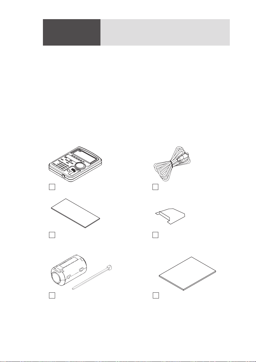
2.1 Check at Unpacking - - - - - - - - - - - - - - - - - - - - - - - - - - - - - 2-1
2.2 Handling Precautions - - - - - - - - - - - - - - - - - - - - - - - - - - - - 2-2
2.3 Combination with Other Options - - - - - - - - - - - - - - - - - - - - 2-2
2.4 Connecting the Remote Controller Cable - - - - - - - - - - - - - - - 2-3
2.5 Installation of the Split Cores - - - - - - - - - - - - - - - - - - - - - - - 2-4
2.6 Installation of the Connector Cover - - - - - - - - - - - - - - - - - - - 2-4
2.7 Moving Precautions - - - - - - - - - - - - - - - - - - - - - - - - - - - - - 2-5
2.8 How to Use the Magnet Sheet - - - - - - - - - - - - - - - - - - - - - - 2-6
2.9 Quick Reference Card- - - - - - - - - - - - - - - - - - - - - - - - - - - - 2-6
Chapter 3 Operation Check 3-1
3.1 Checking the Initial Setup Status - - - - - - - - - - - - - - - - - - - - 3-1
3.2 Operation Check - - - - - - - - - - - - - - - - - - - - - - - - - - - - - - - 3-3
Chapter 4 Operation Method 4-1
4.1 Basic Operation of the Remote Controller - - - - - - - - - - - - - - 4-1
4.2 Functions in Common with the PCR-LA AC Power Supply - - 4-1
4.3 Functions Extended by Using the Remote Controller - - - - - - - 4-3
Chapter 5 Parts Names and Functions 5-1
Chapter 6 Maintenance 6-1
6.1 Cleaning - - - - - - - - - - - - - - - - - - - - - - - - - - - - - - - - - - - - - 6-1
6.2 Before Requesting a Repair - - - - - - - - - - - - - - - - - - - - - - - - 6-2
Chapter 7 Specifications 7-1
7.1 Specifications - - - - - - - - - - - - - - - - - - - - - - - - - - - - - - - - - 7-1
7.2 Dimensions - - - - - - - - - - - - - - - - - - - - - - - - - - - - - - - - - - - 7-2

IV Contents RC03-PCR-LA
Appendix A-1
A.1 Hierarchy of Remote Controller Key Operating Menus - - - - - A-1
A.2 Power Line Abnormality Simulation Operation Setting Sheet - A-4
Index - - - - - - - - - - - - - - - - - - - - - - - - - - - - - - - - - - - - - - - I-1

RC03-PCR-LA General 1-1
Chapter 1
General
Outlines and describes the features of the RC03-PCR-LA Remote
Controller.
1.1 Outline
This device (RC03-PCR-LA) is a remote controller for the PCR-LA
Series AC power supplies. Use of the RC03-PCR-LA with a PCR-LA
AC power supply allows power line abnormality simulation.
1.2 Features
A dedicated key is provided for data setting of power line abnormal-
ity simulation.
Power line abnormality simulation enables simulation of interruption,
fast voltage dip (dip) or fast voltage swell (pop).
The function is used to test switching power supplies or electronics
devices.
1.3 Applicable Product Version
This Remote Controller requires the PCR-LA Series AC power sup-
plies equipped with ROM of version 3.0X.
This Operation Manual applies to the RC04-PCR-LA Remote Con-
trollers equipped with ROM of version 1.0X.
When making an inquiry about the product, please provide us with
the following information:
- Model name
- ROM version
- Serial number
For the procedure for checking the ROM version of the Remote Con-
troller, see “3.2 Operation Check”. For the procedure for checking the
ROM version of the PCR-LA Series AC power supply, see the PCR-
LA Series AC Power Supply Operation Manual.

1-2 General RC03-PCR-LA

RC03-PCR-LA Precautions and Preparation for Use 2-1
Chapter 2
Precautions and Preparation for Use
Provides the precautions and preparation information that must be
understood for use of the Remote Controller.
2.1 Check at Unpacking
The RC03-PCR-LA Remote Controller was carefully tested and
inspected, both mechanically and electrically, before shipment to
ensure its normal operation. Check the Remote Controller upon
receipt for damage that might have occurred during transportation.
Also, check that all items listed below have been provided. If the
device appears to be damaged or if any accessory missing, notify
Kikusui distributor/agent.
Fig.2-1 Items Contained in the Package
Remote controller (1)
Operation Manual (1 copy)
[Z1-002-752]
Magnet sheet (1 sheet)
[R7-000-001]
Split cores (with stopper bands) (2pcs.)
[67-90-0080] [P4-000-551]
Connector cover (1)
[Q1-300-006]
Remote controller cable (1 pc.)
[85-50-0140]
[67-90-0080]
[P4-000-551]

2-2 Precautions and Preparation for Use RC03-PCR-LA
2.2 Handling Precautions
■Do not drop the remote controller or subject it to other
impact.
■Do not place the remote controller where it could be
exposed to water or other liquid.
■Do not use or store the remote controller in direct sunlight.
■Do not use of store the remote controller in an area sus-
ceptible to rapid temperature changes.
■When the remote controller is used with the provided mag-
net sheet, which attaches to the back of the remote con-
troller, never place the remote controller near magnetic-
susceptible items, such as floppy disks and credit cards.
2.3 Combination with Other Options
PCR-LA Series AC power supplies are provided with a variety of
options in addition to the RC03-PCR-LA Remote Controller. Note
that this Remote Controller cannot be used simultaneously with
another option.

RC03-PCR-LA Precautions and Preparation for Use 2-3
2.4 Connecting the Remote Controller Cable
•Before connecting the controller cable, always turn
OFF the PCR-LA AC power supply POWER switch.
When removing the cable, first turn the POWER
switch of the PCR-LA power supply OFF.
•When turning ON the PCR-LA AC power supply POWER
switch, the PCR-LA AC power supply identifies the Remote
Controller that is connected. Therefore, before turning ON the
PCR-LA AC power supply POWER switch, connect the
Remote Controller to the PCR-LA AC power supply.
1. Connect the controller cable connector with a protection
cover to one of the two connectors (see Fig. 2-2) in the
remote controller. Exercise care that the orientation of the
connector is correct.
2. Insert the protection cover, cover the connector and turn the
cover clockwise to fix it securely.
3. Connect the other connector of the remote cable to the TO
REMOTE CONTROLLER connector on the front of the
PCR-LA power supply. In this case, align the cable connec-
tor such that it is oriented with that of the connector on the
front panel.
Fig.2-2 Connecting the Remote Controller Cable
CAUTION
NOTE

2-4 Precautions and Preparation for Use RC03-PCR-LA
2.5 Installation of the Split Cores
1. Unlock the core and open it.
2. Close the core so that the cable is not caught in it.
3. As shown in Fig. 2-3, tie up the cable with the accompany-
ing stopper band. Keep the distance between the plug and
the core below 100 mm.
Fig.2-3 Location of Split Core Installation
2.6 Installation of the Connector Cover
Install the connector cover of the 8P mini plug connector which is not
used.
Installation
1. As shown in Fig. 2-4, insert the accompanying connector
cover from the lower part of the connector.
2. Insert the cover till it is locked.
Fig.2-4 Connector Cover Installation
Within 100 mm
Within 100 mm

RC03-PCR-LA Precautions and Preparation for Use 2-5
Removal
1. As shown in Fig. 2-5, unlock the connector cover with twee-
zers.
2. Slowly pulled down the connector cover.
Fig.2-5 Connector Cover Removal
2.7 Moving Precautions
■Before moving the PCR-LA AC power supply, always dis-
connect the controller cable.
Moving a PCR-LA AC power supply with this device connected may
place unreasonable stress on the remote controller cable or cause the
remote controller to fall.
■When the magnet sheet is used, do not move a PCR-LA AC
power supply with the remote controller attached to the
side of the equipment.
Vibration during movement may cause the remote controller to fall.
■When moving the equipment, follow the instructions given
in the PCR-LA AC Power Supply Operation Manual.

2-6 Precautions and Preparation for Use RC03-PCR-LA
2.8 How to Use the Magnet Sheet
The Remote Controller has a magnet sheet that can be attached to the
back of the remote controller. This allows the remote controller to be
placed on the side panel of the PCR-LA AC power supply or other
steel surface.
Fig.2-6 Attaching the Magnet Sheet
•When the provided magnet sheet is on the back of
the remote controller, never place the remote control-
ler near magnetic-susceptible items, such as floppy
disks and credit cards.
2.9 Quick Reference Card
The remote controller has a quick reference card that briefly describes
keys and simulation waveforms. This card is useful when using the
memory and simulation functions.
Fig.2-7 Quick Reference Card
CAUTION

RC03-PCR-LA Operation Check 3-1
Chapter 3
Operation Check
Describes the operation check that must be conducted prior to opera-
tion of the Remote Controller.
After connecting the Remote Controller by the steps described in
Chapter 2, check the Initial Setup Status and make an operation
check. Always make an operation check as described in this chapter,
if you have installed a new Remote Controller or changed its location,
if the operator changes, or if the Remote Controller has not been used
for a long time.
Before operating this device, read through the PCR-LA AC Power
Supply Operation Manual and gain an understanding of the basic
operations of the AC power supply.
3.1 Checking the Initial Setup Status
The condition in which a PCR-LA AC power supply and this device
are simultaneously purchased and power is fed for the first time (fac-
tory shipment status) is called Initial Setup Status.
The main setting in the Initial Setup Status are as follows:
• OUTPUT OFF
•RANGE 100 V
•AC/DC AC
• Frequency 50.00 Hz
•Voltage 0.0 V
• Display mode Voltmeter
If the Remote Controller is not in the Initial Setup Status, use the reset
function to activate the Initial Setup Status. Reset can be performed
either on the PCR-LA AC power supply or via the Remote Controller.
To perform a reset on the PCR-LA AC power supply, see instructions
in the PCR-LA AC Power Supply Operation Manual.
Note that performing a reset cancels all settings made thus far and
activates the Initial Setup Status.

3-2 Operation Check RC03-PCR-LA
• Home Position
The status in effect immediately after the POWER switch is
turned ON is called the Home Position (regardless of OUT-
PUT ON/OFF). To return to the Home Position from another
mode, press the ESC key.
•ENTER Wait
This is the condition in which the ENTER key has not yet
been pressed to initiate the operations performed thus far. In
this condition, the ENTER LED on the Remote Controller
blinks. To cancel a operation before pressing the ENTER key,
press the ESC key.
ENTER Wait for this device has the same meaning as the
ENT Wait of the PCR-LA AC power supplies.
DESCRIPTION

RC03-PCR-LA Operation Check 3-3
3.2 Operation Check
•Remote Controller operation must be checked after
the operation check of the PCR-LA AC power supply
has been completed.
Operation Check Procedure
The following describes how to make an operation check from the
Initial Setup Status.
1. Tu rn the PCR-LA AC power supply POWER switch ON.
The Remote Controller’s display unit shows the ROM version for
a few seconds.
Fig.3-1 ROM Version Display
After a few seconds, the Home Position appears.
2. Press the V key to select the voltage setting mode.
This causes both the V and SET LEDs to light up.
3. Tu rn the rotary encoder to confirm that the voltage varies.
This completes the operation check.
This operation check does not check all functions. However, if the
operation check has been complete, the main functions operate cor-
rectly.
CAUTION

3-4 Operation Check RC03-PCR-LA

RC03-PCR-LA Operation Method 4-1
Chapter 4
Operation Method
Describes the operations of the Remote Controller and the extended
functions of the PCR-LA AC power supply.
4.1 Basic Operation of the Remote
Controller
Remote controller operation is designed to be as much as possible the
same as that of the PCR-LA AC power supply control panel. How-
ever, part of the operation and operation of new functions provided by
the Remote Controller differ from that of the PCR-LA power supply
control panel.
4.2 Functions in Common with the PCR-LA
AC Power Supply
This section discusses the functions common to the Remote Control-
ler and the PCR-LA AC power supply control panel. The following
functions are the same key operation as that of the PCR-LA AC
power supply control panel. For details about operation, refer to the
PCR-LA AC Power Supply Operation Manual.
Ta b le 4-1 Functions Whose Key Operation is the Same as
That of the PCR-LA AC Power Supply
* The Remote Controller makes the selected digit brighter than the other digits.
Voltage Setting Function
To enter the voltage setting mode, press the V key in the Home Position.
Frequency Setting Function
To enter the frequency setting mode, press the F key in the Home
Position.
Functions Key operation
OUTPUT ON/OFF OUTPUT key
Key-lock function KEYLOCK (SHIFT, 4)
Output voltage range change RANGE (SHIFT, 7)
Output mode change AC/DC (SHIFT, 8)
Digit function* +/- (SHIFT, .)

4-2 Operation Method RC03-PCR-LA
Switching the Voltage Display Mode
To switch the voltage display mode on the Remote Controller, press
the Vrms/Vset (SHIFT, V) key in the Home Position.
Change to the Current Display Mode
To enter the current measurement mode, press the I key in the Home
Position.
Memory Function
The RC03-PCR-LA Remote Controller allows read only operation.
Data in memory addresses 0 to 9 can be read by following the same
procedure as that performed with the PCR-LA power supply. To write
data into the memory, perform operations from the PCR-LA power
supply control panel or through the GPIB or RS-232C interface.
Memory Read Procedure
Select the same output voltage mode (AC, DC, or AC + DC) as that
used when setting the memory. To read the contents stored at each
address (“ADRS”), follow the procedure specified below.
1. Press the ESC key to select the Home Position.
2. Press the MEM key to light up the MEM LED.
3. Enter a memory address using the numeric keys or rotary
encoder.
The memory address entered will be indicated in the rightmost
area of the 7-segment LEDs.
Fig.4-1 Displaying a Memory Address
This causes the set value stored in the entered memory address to
be read.
Pressing the V key in the voltage setting mode causes a voltage
value to appear on the 7-segment LED, while pressing the F key
in the frequency setting mode causes a frequency value to appear.
To return the memory address display, press the ESC or MEM
key.
4. To confirm the read value, press the ENTER key. To cancel it,
press the ESC key.
This allows you to exit the memory address display.
This manual suits for next models
1
Table of contents
Other Kikusui Remote Control manuals
Popular Remote Control manuals by other brands

Sony
Sony RM-V40A operating instructions

Amulet Devices
Amulet Devices Remote Product guide

Philips
Philips SBCRU510/00B Instructions for use

Panasonic
Panasonic WVCU650 - SYSTEM CONTROLLER ADDENDUM operating instructions

NKE
NKE Pad Pilot Series USER MANUAL & INSTALLATION SHEET

TouchTunes
TouchTunes Remote Control user guide