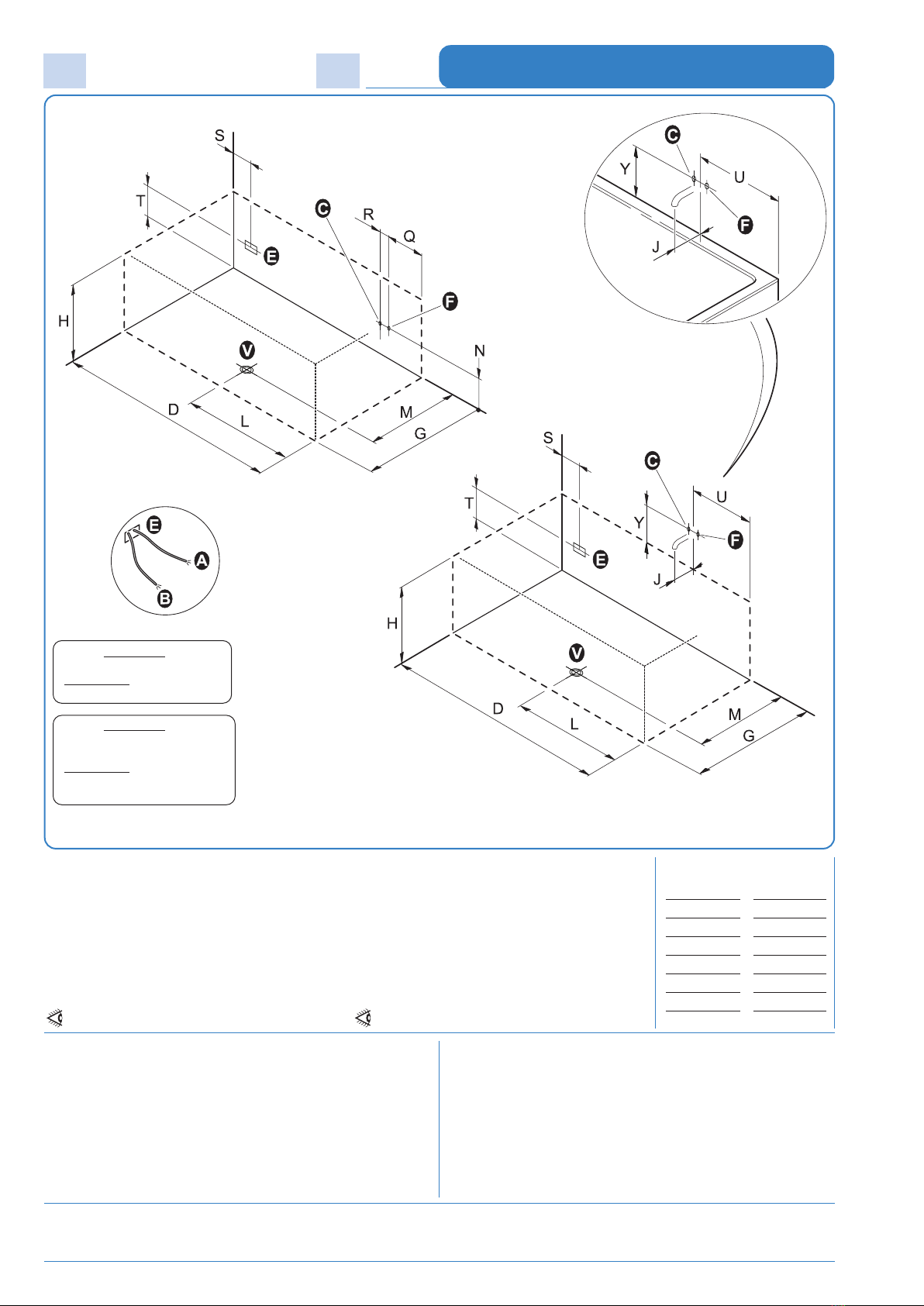
Il disegno rappresenta la versione SINISTRA. La versione DESTRA è speculare.
The drawing show the LEFT side version. The RIGHT side version is mirrow-like.
I dati e le caratteristiche indicate non impegnano la SFA S.p.A., che si riserva il diritto di apportare tutte le modiche ritenute opportune senza obbligo di preavviso o sostituzione
Accertarsi che l’impianto elettrico dello stabile sia conforme alle norme CEI 64.8 e protetto da un
interruttore dierenziale accertandosi che l’impianto di messa a terra sia eciente e conforme alle
disposizioni CEI. Il collegamento elettrico dell’impianto idromassaggio, va eseguito in modo sso
e permanente e deve essere controllato da un interruttore omnipolare con apertura dei contatti di
almeno 3 mm, ed avere un potere di interruzione pari a 16A o 25A (a seconda del tipo di sistema),
posto fuori dalle zone 0,1,2,3 e comunque lontano da possibili erogazioni o spruzzi d’acqua.
Il cavo di alimentazione alla centralina, deve essere del tipo H05 a tre conduttori di sezione non
inferiore a 2,5 mm
2
o 4,0 mm
2
(a seconda del tipo di sistema). Per il passaggio nelle pareti di detto
cavo, usare l’apposito tubo corrugato di tipo PT.
La responsabilità del Costruttore decade nel caso in cui i componenti elettrici dell’apparecchio, ven-
gano manomessi o sostituiti con ricambi non originali e/o non riconosciuti conformi dal Costruttore.
IL COSTRUTTORE NON E’ RESPONSABILE PER I DANNI DOVUTI AD UNA ERRATA O NON CONFORME INSTALLAZIONE.
Make sure the building electrical installation conforms to the EIC 64.8 standard and that it is protected
by a magnetic circuit breaker, ascertaining also that the grounding terminal is ecient and fully com-
pliant with IEC provisions. The electrical connection of the bathtub shall be carried out permanently and
be monitored by a single-pole switch, whose contacts can open 3mm at least and featuring a cut-out
capacity equal to 16A or 25A (based on the system type), located outside areas 0, 1, 2 and 3 and at any
rate, as far as possible from water supply or jets.
The power-cord to the controller must be H05 with a three conductor cross-section is not less than
2,5mm
2
or 4,0 mm
2
(based on the system type). To drive the cord through the walls, use the appropriately
supplied PT corrugated pipe.
This warranty is void if failure has resulted from the electrical components of the appliance being either
tampered with or replaced by second-hand spare parts, and/or spare parts whose conformity is not
acknowledged by the manufacturer..
IN NO EVENT SHALL THE MANUFACTURER BE LIABLE FOR ANY DAMAGES WHATSOEVER THAT MAY ARISE FROM INAPPROPRIATE AND NON-COMPLIANT INSTALLATION PROCEDURES.
Neither the information nor the characteristics reported are binding for SFA S.p.A. which reserves the right to make any improvements, as deemed necessary, without notice or with no liability to replacement.
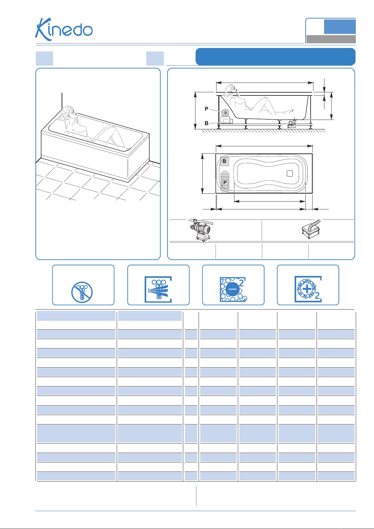
Schema di installazione
Installation plan
A - Allaccio elettrico per idromassaggio IPX5
(scatola con pressacavo PG13,5) Tensione 230V CA (max)
Uscita cavo alimentaz. mt.2 tipo H05-3x2,5 mm2o 3x4,0 mm2
(a seconda del sistema)
B - Uscita cavo equipotenziale - lunghezza 2 mt
C - Attacco acqua calda per rubinetteria 1/2”
F - Attacco acqua fredda per rubinetteria 1/2”
E - Area cavi alimentazione elettrica
V - Scarico a pavimento ø 40mm
L’installazione deve avvenire a pavimento e pareti nite.
A - Electrical connect. for IPX5 box
(PG13,5 junction box with cable seal) 230 V AC (max.)
Voltage 2 m. power cable output, H05-3x2,5 mm2o 3x4,0 mm2
type (based on the system type).
B - Equipotential bonding conductor output - lenght 2mt
C - Hot water tting for 1/2” tapware
F - Cold water tting for 1/2” tapware
E - Line cord area
V - ø 40mm drain tting
Installation should occur once both the oor and walls are completed.
Misure sono in “cm”
Measurement in “cm”
VASCA
BATHTUB
COROLLA - 170x70
Rubinetteria a bordo vasca
Bath-side tapware
Rubinetteria a muro
Wall-mounted tapware
D = 170
G = 70
H = 61
L = 85
M = 55
N = 35
Q = 50
R = 8
S = 15
T = 35
U = 50
Y = 13
J = min. 13
Versione “Senza sistema”:
NO predisposizioni “A” - “B” - “E”
“Without system” version:
NO predispositions “A” - “B” - “E”
Versione “Senza sistema”
+ SOUNDLIGHT SYSTEM (opzionale):
SI predisposizioni “A” - “B” - “E”
“Without system” version
+ SOUNDLIGHT SYSTEM (opzionale)::
YES predispositions “A” - “B” - “E”