OPERATION
INSTALLING THE CORRECT FILTER FOR THE APPLICATION
Before reinstalling the cover/motor assembly on, it is important to determine the desired
cleaning application, wet or dry vacuuming. Each cleaning application requires different types of
filters.
DRY VACUUMING OPERATIONAL STEPS
Before vacuuming dry materials, it is important that you have read and understood the
safety rules in this manual.
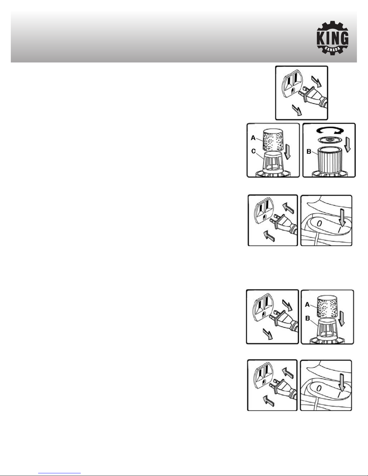
1) Unplug the power cord from the power source.
2) Remove the cover/motor assembly, for normal vacuuming operation, a clean and dry foam
filter should be installed. If the vacuuming operation is extremely dusty, a clean and dry
cartridge filter should be installed instead. Slide the foam filter (A) Fig.9 or the cartridge
filter (B) over the cage (C). If it is necessary to vacuum dry materials and you have just
finished vacuuming wet materials, the foam or cartridge filter must be completely dried or else
they will clog up quickly and will be difficult to clean. The foam or cartridge filter can be dried
quickly by running the vacuum for 5-10 minutes without the hose installed.
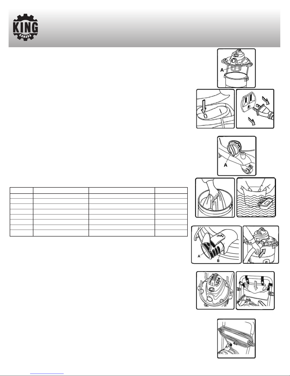
3) Reposition and secure the cover/motor assembly to the tank.
4) Attach the flex hose to the inlet on the front of the vacuum.
5) Assemble the 2 extension wands and the contour handle together and then attach hose to
contour handle.
6) Attach either the floor sweep, crevice tool or gulper tool to the other end of the extension
wand.
7) Plug the power cord to a 110V power source.
8) Start the vacuum by pushing the On/Offswitch to the On position as shown in Fig.10. The On
position is indicated by the international symbol “I” on the switch.
9) Once the vacuuming operation is finished, push the switch to the Off position indicated by the
international symbol “O” on the switch and unplug the power cord from the power source.
10) Remove the cover/motor assembly and lay it aside, being careful not to damage the filter
and dump the tank contents into a suitable waste disposal container. Airborn dust will be
produced when cleaning, wear dust mask!
Warning!
Never use the cartridge filter for vacuuming wet materials. When vacuuming fine dust, it will be
necessary to clean the foam and cartridge filters at more frequent intervals.
WET VACUUMING OPERATIONAL STEPS
Before vacuuming wet materials, it is important that you have read and understood the
safety rules in this manual.
1) Unplug the power cord from the power source.
2) Remove the cover/motor assembly and install a clean and dry foam filter.If wet vacuuming
under normal conditions or when vacuuming large amounts of liquid, only install the foam filter,
slide the foam filter (A) Fig.11over the cage (B). Make sure the inside of the tank is clean.
3) Reposition and secure the cover/motor assembly.
4) Attach the flex hose to the inlet on the front of the vacuum.
5) Assemble the 2 extension wands and the contour handle together and then attach hose to
contour handle.
6) Attach either the floor sweep, crevice tool or gulper tool to the other end of the extension
wand. For wet applications, remove the brush insert from the floor sweep by pressing the 2
snap points at each end of the floor sweep, the assembly will pop out, replace it with the
squeegee insert and snap it back into the floor sweep.
7) Plug the power cord to a power source.
8) Start the vacuum by pushing the On/Off switch to the On position as shown in Fig.12. The On
position is indicated by the international symbol “I” on the switch.
9) When vacuuming large amounts of liquid, do not completely immerse the nozzle accessory
in the liquid, leave a gap at the top of the nozzle accessory opening to allow air inflow.
10) Once the vacuuming operation is finished, push the switch to the Offposition indicated by
the international symbol “O” on the switch and unplug the power cord from the power source.
Warning!
Never use the cartridge filter for vacuuming wet materials.
The foam filter should be cleaned after each wet vacuuming operation.
Should it become necessary to pick up the vacuum to move it, DO NOT pick up the vacuum by
the top handle unless the tank is empty. Do not pull the vacuum by the hose, this may tip the
vacuum over if the wheels are obstructed in any way.
Figure 9
Figure 10
Figure 11
Figure 12