(714) 891-0008 • www.kinginstrumentco.comWhen it comes to ow...we’re instrumental. 2
CAUTION
• 7450 Series meters have o-ring seals. Use with incompatible uid-
may cause o-rings to swell which may cause glass tube to fail.
• Extra caution must be exercised when meters are used in high
pressure gas cylinder applications. Pressure regulators should be
installed at the cylinder and at the inlet of the meter.
• Serious property damage and great personal injury could occur as
the result of a meter misused or used in an unsuitable application.
CLEANING
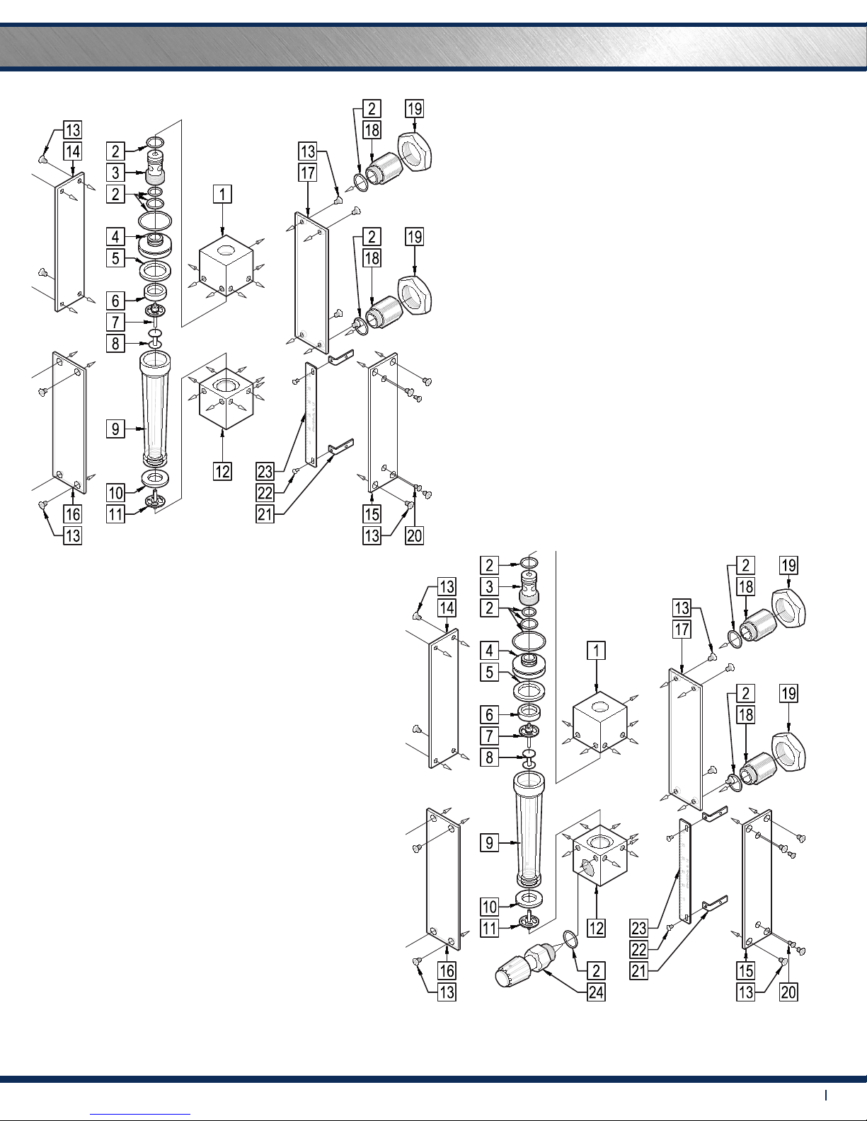
Carefully remove the owmeter from the piping system. Remove the
front and back shield. Remove the end ttings using a 7/8” wrench. Us-
ing a 3/16” hex key, back o the compression screw by turning counter
clockwise. This will release the compression of the glass tube. Carefully
remove the screws that hold the outlet block. Remove the outlet block
and internals. Remove glass tube.
Valve Models: Remove valve from the bottom block using a 7/8” open
ended wrench. Disassembly of valve is not recommended. Outer valve
o-ring should be replaced during meter maintenance and cleaning.
All components are now fully accessible for cleaning. Components can
be cleaned with a mild soap solution. This will be an eective cleaner
of rust stains. A bottle brush may be helpful in cleaning the inside of
the glass tube. Caution must be used so that materials of construction
are not damaged by cleaning solutions. Hard water deposits can be
removed with a 5% acetic acid solution (vinegar). Before the meter is
reassembled, inspect all parts for damage. O-rings should be replaced
during meter maintenance and cleaning.
To reassemble, position the glass tube on the bottom block and
center onto bottom gasket. Insert oat, if on a guide rod make sure
the bottom end of the guide rod is inserted into the center hole of the
bottom oat stop. Re-install the outlet block. Using a 3/16” hex key turn
compression screw counterclockwise while keeping the glass tube
centered between the bottom and top gaskets. Re-install end ttings,
valve and shields.
REPAIR
7450 meters that require repair should be sent to the factory. Please
call for a Return Merchandise Authorization (RMA) number and return
instructions.
WARNING:
Pressure and temperature ratings are based on a study of the engi-
neering data for particular materials used in construction and on the
design of individual models. This information is supplemented by
destructive test results. Meters with stainless enclosures must never be
operated without shields securely in place. Meters exposed to dicult
environments such as those created by certain chemicals, excessive
vibration or other stress inducing factors could fail at or below the
suggested maximums. Never operate meters above pressure and
temperature maximums. It is strongly recommended that all meter
installations utilize an appropriate pressure relief valve and/or rupture
disc. The pressure settings and locations of these devices should be
such that meters cannot be over pressurized. Meter failure could
result in damage to equipment and serious personal injury. Always
use suitable safety gear, including OSHA approved eye protection
when working around meters in service. We are happy to pass along
chemical compatibility information that has been published by the
manufacturer’s of raw materials used in our products; however, this
information should not be construed as a recommendation made by
King Instrument Company, Inc. for a specic application.
FLOAT TYPES AND ORIENTATIONS
7450 Series Installation Instructions
Maximum Non-Shock Pressure and Temperature
Temperature Pressure
200° F 200 psig
Ambient Temp. 33° F -125° F
Pressure and temperature ratings are based on a study of the engineering data
for particular materials used in construction and on the design of individual
models. This information is supplemented by destructive test results. Meters with
stainless enclosures must never be operated without shields securely in place.
Meters exposed to difficult environments such as those created by certain
chemicals, excessive vibration or other stress inducing factors could fail at or
below the suggested maximums. Never operate meters above pressure and
temperature maximums. It is strongly recommended that all meter installations
utilize an appropriate pressure relief valve and/or rupture disc. The pressure
settings and locations of these devices should be such that meters cannot be
over pressurized. Meter failure could result in damage to equipment and serious
personal injury. Always use suitable safety gear, including OSHA approved eye
protection when working around meters in service. We are happy to pass along
chemical compatibility information that has been published by the manufacturer's
of raw materials used in our products; however, this information should not be
construed as a recommendation made by King Instrument Company, Inc. for a
specific application.
7450 meters that require repair should be sent to the factory. Please call for a
Return Merchandise Authorization (RMA) number and return instructions.
-7450 Series meters have o-ring seals. Use with incompatible fluids may cause
o-rings to swell which may cause glass tube to fail.
1) Inspect meter for damage that may have occurred during shipping.
Report any damage to the container to the freight carrier immediately.
This is important information. Read it carefully
before beginning work.
2) Make sure your pressure, temperature, fluid and other
requirements are compatible with the meter including o-rings.
3) Select a suitable location for installation to prevent excess stress
on the meter which may result from:
a) Misaligned pipe.
b) The weight of related plumbing.
c) "Water Hammer" which is most likely to occur when flow is
suddenly stopped as with quick closing solenoid operated valves.
(If necessary, a surge chamber should be installed. This will also be
useful in pressure start-up situations.)
d) Thermal expansion of liquid in a stagnated or valve isolated
system.
f) Instantaneous pressurization which will stress the meter and
could result in tube failure.
NOTE: In closed thermal transfer or cooling systems, install the meter
in the cool side of the line to minimize meter expansion and
contraction and possible fluid leaks at the threaded connections.
4) Handle the meter carefully during installation.
a) Use an appropriate amount of teflon tape on external pipe
threads before making connections. Do not use paste or stick type
thread sealing products.
5) Install the meter vertically with the inlet port at the bottom.
6) Meters with stainless steel fittings will support several feet of pipe
as long as significant vibration or stress resulting from misaligned pipe
are not factors.
EPR 225 °F
Buna-N
Viton
Kalrez
275 °F
350 °F
400 °F
Non-valve
Inlet / Outlet Valve
4,000 psig
1,500 psig
Maximum Non-Shock
Pressure and
Temperature O-Ring Temperature
Ambient
temperature 33° F - 125° F
Viton and Kalrez are registered trademarks of DuPont Dow
Elastomers.
O-Ring Material Maximum
Temperature Meters are not specifically recommended for service other than
water or air. The user must determine meter suitability for use
with other fluids.
e) It is recommended to install valving which will allow the meter to
be drained. Meter should be drained when not in use or prior to
maintenance.
7) Meters used in gas service should have suitable valves plumbed in
at the inlet and outlet of the meter. These valves should be no more
than 1-1/2 pipe diameters from the meter ports. The valve at the
outlet should be used to create back pressure as required to prevent
float bounce. It should be set initially and then left alone. The inlet
valve should be used for throttling purposes. Depending on the
installation, valves may not be essential, but they are most useful in
many installations. Remember: To get a correct reading of flow in gas
service, it is necessary to know the pressure right at the outlet of the
meter (before the valve).
8) Pressure and temperature maximums must never be exceeded.
-Extra caution must be exercised when meters are used in high pressure gas
cylinder applications. Pressure regulators should be installed at the cylinder and
at the inlet of the meter.
-Serious property damage and great personal injury could occur as the result of a
meter misused or used in an unsuitable application.
LP FLOAT
Maximum flow
meter capacity
with limited
viscosity immunity
OUTLET END FITTING
O-RING
COMPRESSION FITTING
COMPRESSION SEAT
INLET SEAL
INLET FLOAT STOP /
INLET END FITTING
SIDE PLATE /
SIDE PLATE
SCALE SIDE PLATE
OUTLET SEAL
OUTLET FLOAT STOP
FLOAT STOP /
FLOAT
GLASS METER TUBE
SHIELD (CLEAR)
SHIELD (WHITE)
END FITTING
END FITTING NUT
SCALE BRACKET
SCALE BRACKET
SCALE PLATE
SCALE PLATE
VALVE ASSEMBLY
OUTLET END FITTING
O-RING
COMPRESSION FITTING
COMPRESSION SEAT
INLET SEAL
INLET FLOAT STOP /
INLET END FITTING
SIDE PLATE /
SIDE PLATE
SCALE SIDE PLATE
OUTLET SEAL
OUTLET FLOAT STOP
OUTLET FLOAT STOP /
FLOAT
GLASS METER TUBE
SHIELD (CLEAR)
SHIELD (WHITE)
END FITTING
END FITTING NUT
SCALE BRACKET
SCALE BRACKET
SCALE PLATE
SCALE PLATE
BLOCK
EXTENSION ASSEMBLY
BLOCK
SHIELD SCREW
HOLDER
EXTENSION ASSEMBLY
SCREW
SCREW
BLOCK
EXTENSION ASSEMBLY
BLOCK
SHIELD SCREW
HOLDER
EXTENSION ASSEMBLY
SCREW
SCREW
GV FLOAT
Highest immunity
to viscous fluids
with medium
capacity.
SL FLOAT
Maximum flow
meter capacity
with limited
viscosity immunity
4X
4X 4X
2X
2X
2X
4X
4X
4X 4X
2X
2X
2X
4X
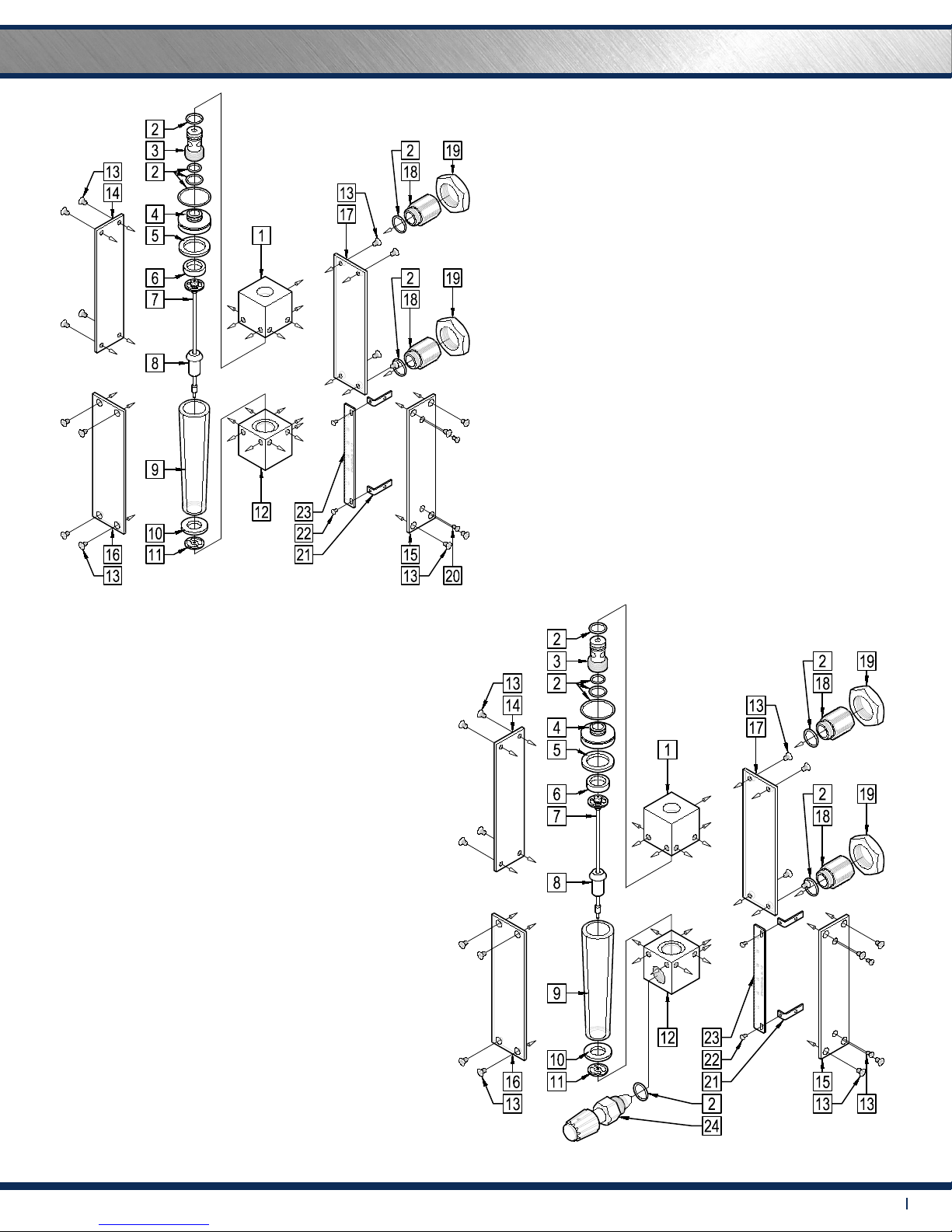
Carefully remove the flowmeter from the piping system. Remove the front and
back shield. Remove the end fittings using a 78" wrench. Using a 316" hex key,
back off the compression screw by turning counter clockwise. This will release
the compression of the glass tube. Carefully remove the screws that hold the
outlet block. Remove the outlet block and internals. Remove glass tube.
Valve Models: Remove valve from the bottom block using a 78" open ended
wrench. Disassembly of valve is not recommended. Outer valve o-ring should be
replaced during meter maintenance and cleaning.
To reassemble, position the glass tube on the bottom block and center onto
bottom gasket. Insert float, if on a guide rod make sure the bottom end of the
guide rod is inserted into the center hole of the bottom float stop. Re-install the
outlet block. Using a 316" hex key turn compression screw counterclockwise while
keeping the glass tube centered between the bottom and top gaskets. Re-install
end fittings, valve and shields.
All components are now fully accessible for cleaning. Components can be
cleaned with a mild soap solution. This will be an effective cleaner of rust stains.
a bottle brush may be helpful in cleaning the inside of the glass tube. Caution
must be used so that materials of construction are not damaged by cleaning
solutions. Hard water deposits can be removed with a 5% acetic acid solution
(vinegar). Before the meter is reassembled, inspect all parts for damage. O-rings
should be replaced during meter maintenance and cleaning.
Pressure and temperature ratings are based on a study of the engineering data
for particular materials used in construction and on the design of individual
models. This information is supplemented by destructive test results. Meters with
stainless enclosures must never be operated without shields securely in place.
Meters exposed to difficult environments such as those created by certain
chemicals, excessive vibration or other stress inducing factors could fail at or
below the suggested maximums. Never operate meters above pressure and
temperature maximums. It is strongly recommended that all meter installations
utilize an appropriate pressure relief valve and/or rupture disc. The pressure
settings and locations of these devices should be such that meters cannot be
over pressurized. Meter failure could result in damage to equipment and serious
personal injury. Always use suitable safety gear, including OSHA approved eye
protection when working around meters in service. We are happy to pass along
chemical compatibility information that has been published by the manufacturer's
of raw materials used in our products; however, this information should not be
construed as a recommendation made by King Instrument Company, Inc. for a
specific application.
7450 meters that require repair should be sent to the factory. Please call for a
Return Merchandise Authorization (RMA) number and return instructions.
-7450 Series meters have o-ring seals. Use with incompatible fluids may cause
o-rings to swell which may cause glass tube to fail.
1) Inspect meter for damage that may have occurred during shipping.
Report any damage to the container to the freight carrier immediately.
This is important information. Read it carefully
before beginning work.
2) Make sure your pressure, temperature, fluid and other
requirements are compatible with the meter including o-rings.
3) Select a suitable location for installation to prevent excess stress
on the meter which may result from:
a) Misaligned pipe.
b) The weight of related plumbing.
c) "Water Hammer" which is most likely to occur when flow is
suddenly stopped as with quick closing solenoid operated valves.
(If necessary, a surge chamber should be installed. This will also be
useful in pressure start-up situations.)
d) Thermal expansion of liquid in a stagnated or valve isolated
system.
f) Instantaneous pressurization which will stress the meter and
could result in tube failure.
NOTE: In closed thermal transfer or cooling systems, install the meter
in the cool side of the line to minimize meter expansion and
contraction and possible fluid leaks at the threaded connections.
4) Handle the meter carefully during installation.
a) Use an appropriate amount of teflon tape on external pipe
threads before making connections. Do not use paste or stick type
thread sealing products.
5) Install the meter vertically with the inlet port at the bottom.
6) Meters with stainless steel fittings will support several feet of pipe
as long as significant vibration or stress resulting from misaligned pipe
are not factors.
EPR 225 °F
Buna-N
Viton
Kalrez
275 °F
350 °F
400 °F
Non-valve
Inlet / Outlet Valve
4,000 psig
1,500 psig
Maximum Non-Shock
Pressure and
Temperature O-Ring Temperature
Ambient
temperature 33° F - 125° F
Viton and Kalrez are registered trademarks of DuPont Dow
Elastomers.
O-Ring Material Maximum
Temperature Meters are not specifically recommended for service other than
water or air. The user must determine meter suitability for use
with other fluids.
e) It is recommended to install valving which will allow the meter to
be drained. Meter should be drained when not in use or prior to
maintenance.
7) Meters used in gas service should have suitable valves plumbed in
at the inlet and outlet of the meter. These valves should be no more
than 1-1/2 pipe diameters from the meter ports. The valve at the
outlet should be used to create back pressure as required to prevent
float bounce. It should be set initially and then left alone. The inlet
valve should be used for throttling purposes. Depending on the
installation, valves may not be essential, but they are most useful in
many installations. Remember: To get a correct reading of flow in gas
service, it is necessary to know the pressure right at the outlet of the
meter (before the valve).
8) Pressure and temperature maximums must never be exceeded.
-Extra caution must be exercised when meters are used in high pressure gas
cylinder applications. Pressure regulators should be installed at the cylinder and
at the inlet of the meter.
-Serious property damage and great personal injury could occur as the result of a
meter misused or used in an unsuitable application.
LP FLOAT
Maximum flow
meter capacity
with limited
viscosity immunity
OUTLET END FITTING
O-RING
COMPRESSION FITTING
COMPRESSION SEAT
INLET SEAL
INLET FLOAT STOP /
INLET END FITTING
SIDE PLATE /
SIDE PLATE
SCALE SIDE PLATE
OUTLET SEAL
OUTLET FLOAT STOP
FLOAT STOP /
FLOAT
GLASS METER TUBE
SHIELD (CLEAR)
SHIELD (WHITE)
END FITTING
END FITTING NUT
SCALE BRACKET
SCALE BRACKET
SCALE PLATE
SCALE PLATE
VALVE ASSEMBLY
OUTLET END FITTING
O-RING
COMPRESSION FITTING
COMPRESSION SEAT
INLET SEAL
INLET FLOAT STOP /
INLET END FITTING
SIDE PLATE /
SIDE PLATE
SCALE SIDE PLATE
OUTLET SEAL
OUTLET FLOAT STOP
OUTLET FLOAT STOP /
FLOAT
GLASS METER TUBE
SHIELD (CLEAR)
SHIELD (WHITE)
END FITTING
END FITTING NUT
SCALE BRACKET
SCALE BRACKET
SCALE PLATE
SCALE PLATE
BLOCK
EXTENSION ASSEMBLY
BLOCK
SHIELD SCREW
HOLDER
EXTENSION ASSEMBLY
SCREW
SCREW
BLOCK
EXTENSION ASSEMBLY
BLOCK
SHIELD SCREW
HOLDER
EXTENSION ASSEMBLY
SCREW
SCREW
GV FLOAT
Highest immunity
to viscous fluids
with medium
capacity.
SL FLOAT
Maximum flow
meter capacity
with limited
viscosity immunity
4X
4X 4X
2X
2X
2X
4X
4X
4X 4X
2X
2X
2X
4X
Carefully remove the flowmeter from the piping system. Remove the front and
back shield. Remove the end fittings using a 78" wrench. Using a 316" hex key,
back off the compression screw by turning counter clockwise. This will release
the compression of the glass tube. Carefully remove the screws that hold the
outlet block. Remove the outlet block and internals. Remove glass tube.
Valve Models: Remove valve from the bottom block using a 78" open ended
wrench. Disassembly of valve is not recommended. Outer valve o-ring should be
replaced during meter maintenance and cleaning.
To reassemble, position the glass tube on the bottom block and center onto
bottom gasket. Insert float, if on a guide rod make sure the bottom end of the
guide rod is inserted into the center hole of the bottom float stop. Re-install the
outlet block. Using a 316" hex key turn compression screw counterclockwise while
keeping the glass tube centered between the bottom and top gaskets. Re-install
end fittings, valve and shields.
All components are now fully accessible for cleaning. Components can be
cleaned with a mild soap solution. This will be an effective cleaner of rust stains.
a bottle brush may be helpful in cleaning the inside of the glass tube. Caution
must be used so that materials of construction are not damaged by cleaning
solutions. Hard water deposits can be removed with a 5% acetic acid solution
(vinegar). Before the meter is reassembled, inspect all parts for damage. O-rings
should be replaced during meter maintenance and cleaning.
GV FLOAT LP FLOAT
SL FLOAT SP FLOAT
Pressure and temperature ratings are based on a study of the engineering data for
particular materials used in construction and on the design of individual models.
This information is supplemented by destructive test results. Meters with stainless
enclosures must never be operated without shields securely in place. Meters
exposed to difficult environments such as those created by certain chemicals,
excessive vibration or other stress inducing factors could fail at or below the
suggested maximums. Never operate meters above pressure and temperature
maximums. It is strongly recommended that all meter installations utilize an
appropriate pressure relief valve and/or rupture disc. The pressure settings and
locations of these devices should be such that meters cannot be over pressurized.
Meter failure could result in damage to equipment and serious personal injury.
Always use suitable safety gear, including OSHA approved eye protection when
working around meters in service. We are happy to pass along chemical
compatibility information that has been published by the manufacturer's of raw
materials used in our products; however, this information should not be construed
as a recommendation made by King Instrument Company, Inc. for a specific
application.
Carefully remove the flowmeter from piping system. Remove the 4 screws on each
side holding the side plates on. Remove the side plates. Carefully remove the glass
meter tube from the end fittings. Be sure to not let the internals fall out. Use caution
when removing the glass meter tube. Do not allow float to fall out. Float damage
may result in inaccuracy. All necessary instrument components are now fully
accessible for cleaning with a bottle brush and appropriate mild soap solution*.
Before the meter is reassembled, inspect all parts for damage. O-rings should be
replaced during meter maintenance and cleaning.
To reassemble, install the glass meter tube back onto the end fittings. Reinstall the
side plates. Tighten the 4 screws on each side. Reinstall the instrument into the
plumbing system after removing the old teflon tape (with a wire brush) and
replacing with fresh teflon tape.
*Do not use cleaning agents that will damage float, tube or o-rings.
Meters should be cleaned with a mild soap solution. This will be an effective
cleaner of rust stains. Caution must be used so that materials of construction are
not damaged by cleaning solutions. Hard water deposits can be removed with 5%
acetic acid solution (vinegar).
7460 meters that require repair should be sent to the factory. Please call for a
Return Merchandise Authorization (RMA) number and return instructions.
-O-rings should be replaced if meter is disassembled after it has been in service.
-Serious property damage and great personal injury could occur as the result of a
meter misused or used in an unsuitable application.
CAUTION:
CLEANING:
REPAIR:
WARNING:
FLOAT TYPES AND
ORIENTATIONS:
LP FLOAT
Maximum flow meter
capacity with limited
viscosity immunity
GV FLOAT (Rib Guided)
Highest immunity to
viscous fluids with
medium capacity.
SL FLOAT
Maximum flow meter
capacity with limited
viscosity immunity
GS FLOAT (Rib Guided)
Maximum flow meter
capacity with limited
viscosity immunity
SP FLOAT
Maximum flow meter
capacity with limited
viscosity immunity
GV FLOAT (Pole Guided)
Highest immunity to
viscous fluids with
medium capacity.
GS FLOAT (Pole Guided)
Maximum flow meter
capacity with limited
viscosity immunity