(714) 891-0008 • www.kinginstrumentco.comWhen it comes to ow...we’re instrumental. 4
7750 Series Installation Instructions
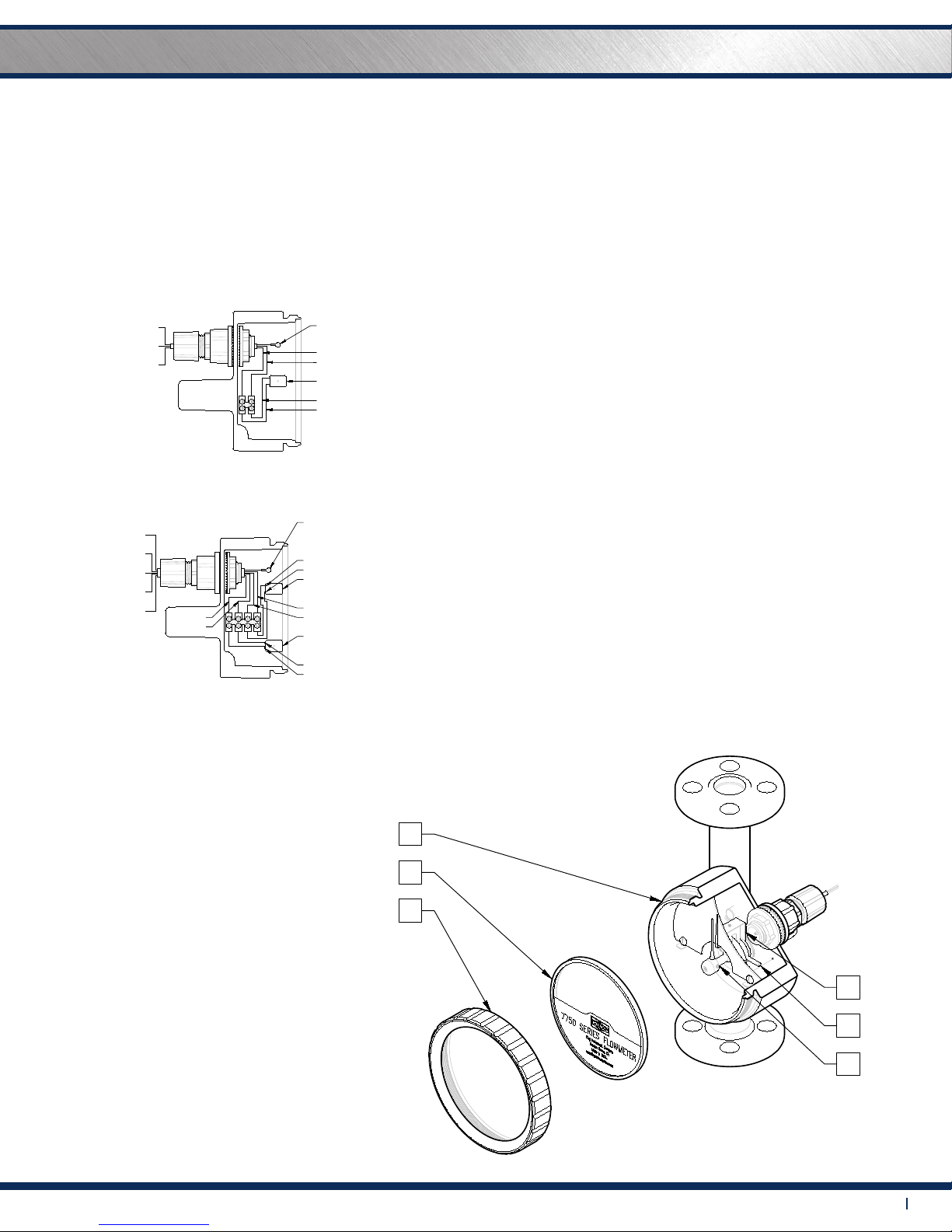
7750 SERIES ASSEMBLY
INDUCTIVE SLOT SENSOR
PARTS LIST:
1. Shield Retainer
2. Shield and Gasket
3. Indicator Housing/
Meter Tube Assembly
4. Pointer Hub and
Pointer Needle
5. Alarm Nut
6. Alarm Sensor Bracket
7750 SERIES INDUCTIVE SLOT SENSOR
All 7750 Series owmeters may be tted with one or two inductive
slot sensors. Inductive slot sensors are 2-wire, DC, low current devices
and are designed to be used with a remote barrier / switch isolator
capable of powering the sensor and providing the desired switching
option(s). Barrier / switch isolators are available with 220VAC, 110VAC
or 24VDC supply voltage requirements, contain single pole double
throw (SPDT) relays, and are DIN rail mountable. (Only 24VDC units
are actually powered by the rail.) See barrier / switch
INDUCTIVE SLOT SENSOR-ELECTRICAL SPECIFICATIONS
TYPE: Inductive
SUPPLY VOLTAGE: 5-25V DC (Switch Isolator)
OUTPUT: NAMUR
OUTPUT LOAD CURRENT: <= 1mA-Float Present
>= 3mA (15mA Max.)-Float Absent
SWITCHING FREQUENCY: 2kHZ
HOUSING RATING: IP67
WIRING: 2 Conductor, NAMUR
POS=BROWN / NEG=BLUE
TERMINALS: #1=POS / #2=NEG
PEPPERL+FUCHS UL: General Purpose
SENSOR APPROVALS CSA: General Purpose
INDUCTIVE SLOT SENSOR
PARTS LIST:
SHIELD RETAINER
1
SHIELD AND GASKET
2
3
4
5
6
7750 SERIES ASSEMBLY
INDICATOR HOUSING/
POINTER HUB AND
ALARM NUT
ALARM SENSOR BRACKET
METER TUBE ASSEMBLY
POINTER NEEDLE
1
2
3
FLOWMETER LIMITED WARRANTY
7750 SERIES
INSTALLATION
INSTRUCTIONS
KING
INSTRUMENT
COMPANY
KING INSTRUMENT COMPANY
12700 Pala Drive, Garden Grove, CA 92841
www.kinginstrumentco.com / (714) 891-0008
Meters are warranted against defects in materials and workmanship to the
original user for a period of thirteen (13) months from the date of factory
shipment, provided the meter is installed, operated and maintained in
accordance with King Instrument Company's instructions and
recommendations.
This warranty does not apply if failure is caused or contributed to by any of
the following: improper handling, improper storage, abuse, unsuitable
application of the product, lack of reasonable and necessary maintenance,
use exceeding suggested pressure and temperature maximums, improper
packaging for return, or repairs made or attempted to be made by anyone
other than King Instrument Company, Inc.
KING INSTRUMENT COMPANY, INC. MAKES NO WARRANTY
AS TO THE FITNESS OF ITS PRODUCTS FOR SPECIFIC
APPLICATIONS.
This warranty is valid for the original end-user only and does not apply to
products that have been damaged or modified. This warranty is
non-transferrable and is limited to replacement or repair. The liability of King
Instrument Company arising out of its supply of the products, or their use,
shall not in any case exceed the cost of correcting defects in the products as
set forth above.
THIS WARRANTY IS A LIMITED WARRANTY AND SHALL BE IN
LIEU OF ANY OTHER WARRANTIES, EXPRESSED OR IMPLIED,
INCLUDING BUT NOT LIMITED TO ANY IMPLIED WARRANTY
OR MERCHANTABILITY OR FITNESS FOR A PARTICULAR
PURPOSE. THERE ARE NO OTHER WARRANTIES WHICH
EXIST BEYOND THE DESCRIPTION OR FACE HEREOF.
IN NO EVENT SHALL KING INSTRUMENT COMPANY BE
LIABLE FOR LOSS OF PROFITS, INDIRECT, CONSEQUENTIAL
OR INCIDENTAL DAMAGES.
Products should be returned, prepaid, to King Instrument Company, Inc. with
proof of purchase. Call factory for Return Merchandise Authorization (RMA)
number and return instructions.
2017A
7750 SERIES 4-20 mA TRANSMITTER
To convert the measured flow into a 4-20 mAdc signal, an angle of
rotation transmitter is mounted to the indicator. This device is factory
calibrated to ensure accuracy and should only be adjusted by King
Instrument Company.
4-20 mA TRANSMITTER SPECIFICATIONS:
POWER SUPPLY:
MAXIMUM CURRENT CONSUMPTION:
TEMPERATURE LIMITS:
OUTPUT:
12-33V DC
40 mA
-13°F to 158°F
4 to 20 mAdc
ACCURACY: <=0.5%
LINEARITY: +/- 0.4%
INFLUENCE FROM BEARING: +/- 0.1%
ELECTRICAL CONNECTIONS:
S1
SPANZERO
-
+
OUT
V
TRANSMITTER HOUSING
TRANSMITTER SHAFT
TRANSMITTER
JUMPER WIRE
RED WIRE (+)
BLACK WIRE (-)
V-V+OUT
ext
R
Rext: EXTERNAL RESISTANCE =
POWER SUPPLY (V) -12V
OUTPUT SIGNAL (mA)
H
SINGLE ALARM WIRING DIAGRAM
DUAL ALARM WIRING DIAGRAM
7750 SERIES INDUCTIVE SLOT SENSOR
All 7750 Series flowmeters may be fitted with one or two inductive slot
sensors. Inductive slot sensors are 2-wire, DC, low current devices and are
designed to be used with a remote barrier / switch isolator capable of
powering the sensor and providing the desired switching option(s). Barrier /
switch isolators are available with 220VAC, 110VAC or 24VDC supply voltage
requirements, contain single pole double throw (SPDT) relays, and are DIN
rail mountable. (Only 24VDC units are actually powered by the rail.) See
barrier / switch isolator specifications for electrical connections and further
details.
INDUCTIVE SLOT SENSOR-ELECTRICAL
SPECIFICATIONS
TYPE:
SUPPLY VOLTAGE:
OUTPUT:
OUTPUT LOAD CURRENT:
Inductive
5-25V DC (Switch Isolator)
NAMUR
<= 1mA-Float Present
>= 3mA (15mA Max.)-Float Absent
SWITCHING FREQUENCY: 2kHZ
HOUSING RATING: IP67
WIRING: 2 Conductor, NAMUR
POS=BROWN / NEG=BLUE
TERMINALS: #1=POS / #2=NEG
PEPPERL+FUCHS General Purpose
General Purpose
UL:
CSA:SENSOR APPROVALS:
ELECTRICAL CONNECTIONS
SETTING ALARM TRIGGER POINTS:
1) Unscrew the SHIELD RETAINER to remove the SHIELD and GASKET.
2) Remove the SHIELD and GASKET.
3) Carefully loosen the ALARM NUT. (Loosen just enough to rotate the ALARM
SENSOR BRACKET).
4) Carefully rotate the ALARM SENSOR BRACKET to the desired alarm set
point. If the meter has DUAL ALARMS, set the LOW ALARM set point and then
the HIGH ALARM set point.
5) Tighten the ALARM NUT.
6) Replace the SHIELD and GASKET, secure with the SHIELD RETAINER.
TEMPERATURE INFLUENCE (AMBIENT): +/- 0.03% per degree C
POWER SUPPLY INFLUENCE: +/- 0.1%
LOAD RESISTANCE INFLUENCE: +/- 0.03% at R max.
ZERO POINT MARK
ZERO POINT MARK
(2 WIRE ONLY)
TRANSMITTER - REAR VIEW 2-WIRE CONNECTION
ZERO: POTENTIOMETER P1 FOR
ZERO POINT
POTENTIOMETER P2 FOR
MEASURING RANGE AND
VALUE
SPAN:
SWITCH FOR REVERSING
ROTATION (NOT
APPLICABLE)
S1: H: DC POWER SUPPLY
(-25°C to 70°C)
(12V-33V)
RED-1
BLACK-1
BLACK-2
(GROUND)
RED-2
BLACK-2
BLACK-3
(GROUND)
RED-1
BLACK-1
BROWN
BLUE
BLACK-2
(GROUND)
ALARM
BLACK-1
RED-1
BROWN
BLUE
BLACK-3
BROWN
BLUE
RED-2
BLACK-2
ALARM
SENSOR
ALARM
SENSOR
(HIGH)
(LOW)
(GROUND)
BLACK-1
RED-1
6
5
4
INDUCTIVE SLOT SENSOR
PARTS LIST:
SHIELD RETAINER
1
SHIELD AND GASKET
2
3
4
5
6
7750 SERIES ASSEMBLY
INDICATOR HOUSING/
POINTER HUB AND
ALARM NUT
ALARM SENSOR BRACKET
METER TUBE ASSEMBLY
POINTER NEEDLE
1
2
3
FLOWMETER LIMITED WARRANTY
7750 SERIES
INSTALLATION
INSTRUCTIONS
KING
INSTRUMENT
COMPANY
KING INSTRUMENT COMPANY
12700 Pala Drive, Garden Grove, CA 92841
www.kinginstrumentco.com / (714) 891-0008
Meters are warranted against defects in materials and workmanship to the
original user for a period of thirteen (13) months from the date of factory
shipment, provided the meter is installed, operated and maintained in
accordance with King Instrument Company's instructions and
recommendations.
This warranty does not apply if failure is caused or contributed to by any of
the following: improper handling, improper storage, abuse, unsuitable
application of the product, lack of reasonable and necessary maintenance,
use exceeding suggested pressure and temperature maximums, improper
packaging for return, or repairs made or attempted to be made by anyone
other than King Instrument Company, Inc.
KING INSTRUMENT COMPANY, INC. MAKES NO WARRANTY
AS TO THE FITNESS OF ITS PRODUCTS FOR SPECIFIC
APPLICATIONS.
This warranty is valid for the original end-user only and does not apply to
products that have been damaged or modified. This warranty is
non-transferrable and is limited to replacement or repair. The liability of King
Instrument Company arising out of its supply of the products, or their use,
shall not in any case exceed the cost of correcting defects in the products as
set forth above.
THIS WARRANTY IS A LIMITED WARRANTY AND SHALL BE IN
LIEU OF ANY OTHER WARRANTIES, EXPRESSED OR IMPLIED,
INCLUDING BUT NOT LIMITED TO ANY IMPLIED WARRANTY
OR MERCHANTABILITY OR FITNESS FOR A PARTICULAR
PURPOSE. THERE ARE NO OTHER WARRANTIES WHICH
EXIST BEYOND THE DESCRIPTION OR FACE HEREOF.
IN NO EVENT SHALL KING INSTRUMENT COMPANY BE
LIABLE FOR LOSS OF PROFITS, INDIRECT, CONSEQUENTIAL
OR INCIDENTAL DAMAGES.
Products should be returned, prepaid, to King Instrument Company, Inc. with
proof of purchase. Call factory for Return Merchandise Authorization (RMA)
number and return instructions.
2017A
7750 SERIES 4-20 mA TRANSMITTER
To convert the measured flow into a 4-20 mAdc signal, an angle of
rotation transmitter is mounted to the indicator. This device is factory
calibrated to ensure accuracy and should only be adjusted by King
Instrument Company.
4-20 mA TRANSMITTER SPECIFICATIONS:
POWER SUPPLY:
MAXIMUM CURRENT CONSUMPTION:
TEMPERATURE LIMITS:
OUTPUT:
12-33V DC
40 mA
-13°F to 158°F
4 to 20 mAdc
ACCURACY: <=0.5%
LINEARITY: +/- 0.4%
INFLUENCE FROM BEARING: +/- 0.1%
ELECTRICAL CONNECTIONS:
S1
SPANZERO
-
+
OUT
V
TRANSMITTER HOUSING
TRANSMITTER SHAFT
TRANSMITTER
JUMPER WIRE
RED WIRE (+)
BLACK WIRE (-)
V-V+OUT
ext
R
Rext: EXTERNAL RESISTANCE =
POWER SUPPLY (V) -12V
OUTPUT SIGNAL (mA)
H
SINGLE ALARM WIRING DIAGRAM DUAL ALARM WIRING DIAGRAM
7750 SERIES INDUCTIVE SLOT SENSOR
All 7750 Series flowmeters may be fitted with one or two inductive slot
sensors. Inductive slot sensors are 2-wire, DC, low current devices and are
designed to be used with a remote barrier / switch isolator capable of
powering the sensor and providing the desired switching option(s). Barrier /
switch isolators are available with 220VAC, 110VAC or 24VDC supply voltage
requirements, contain single pole double throw (SPDT) relays, and are DIN
rail mountable. (Only 24VDC units are actually powered by the rail.) See
barrier / switch isolator specifications for electrical connections and further
details.
INDUCTIVE SLOT SENSOR-ELECTRICAL
SPECIFICATIONS
TYPE:
SUPPLY VOLTAGE:
OUTPUT:
OUTPUT LOAD CURRENT:
Inductive
5-25V DC (Switch Isolator)
NAMUR
<= 1mA-Float Present
>= 3mA (15mA Max.)-Float Absent
SWITCHING FREQUENCY: 2kHZ
HOUSING RATING: IP67
WIRING: 2 Conductor, NAMUR
POS=BROWN / NEG=BLUE
TERMINALS: #1=POS / #2=NEG
PEPPERL+FUCHS General Purpose
General Purpose
UL:
CSA:SENSOR APPROVALS:
ELECTRICAL CONNECTIONS
SETTING ALARM TRIGGER POINTS:
1) Unscrew the SHIELD RETAINER to remove the SHIELD and GASKET.
2) Remove the SHIELD and GASKET.
3) Carefully loosen the ALARM NUT. (Loosen just enough to rotate the ALARM
SENSOR BRACKET).
4) Carefully rotate the ALARM SENSOR BRACKET to the desired alarm set
point. If the meter has DUAL ALARMS, set the LOW ALARM set point and then
the HIGH ALARM set point.
5) Tighten the ALARM NUT.
6) Replace the SHIELD and GASKET, secure with the SHIELD RETAINER.
TEMPERATURE INFLUENCE (AMBIENT): +/- 0.03% per degree C
POWER SUPPLY INFLUENCE: +/- 0.1%
LOAD RESISTANCE INFLUENCE: +/- 0.03% at R max.
ZERO POINT MARK
ZERO POINT MARK
(2 WIRE ONLY)
TRANSMITTER - REAR VIEW 2-WIRE CONNECTION
ZERO: POTENTIOMETER P1 FOR
ZERO POINT
POTENTIOMETER P2 FOR
MEASURING RANGE AND
VALUE
SPAN:
SWITCH FOR REVERSING
ROTATION (NOT
APPLICABLE)
S1: H: DC POWER SUPPLY
(-25°C to 70°C)
(12V-33V)
RED-1
BLACK-1
BLACK-2
(GROUND)
RED-2
BLACK-2
BLACK-3
RED-1
BLACK-1
BROWN
BLUE
BLACK-2
(GROUND)
ALARM
BLACK-1
RED-1
BROWN
BLUE
BLACK-3
BROWN
BLUE
RED-2
BLACK-2
ALARM
SENSOR
ALARM
SENSOR
(HIGH)
(LOW)
(GROUND)
BLACK-1
RED-1
SETTING ALARM TRIGGER POINTS
1) Unscrew the SHIELD RETAINER to remove the SHIELD
and GASKET.
2) Remove the SHIELD and GASKET.
3) Carefully loosen the ALARM NUT. (Loosen just enough to rotate
the ALARM SENSOR BRACKET).
4) Carefully rotate the ALARM SENSOR BRACKET to the desired
alarm set point. If the meter has DUAL ALARMS, set the LOW ALARM
set point and then the HIGH ALARM set point.
5) Tighten the ALARM NUT.
6) Replace the SHIELD and GASKET, secure with the
SHIELD RETAINER.
7750 SERIES ASSEMBLY INDUCTIVE SLOT SENSOR
INDUCTIVE SLOT SENSOR
PARTS LIST:
SHIELD RETAINER
1
SHIELD AND GASKET
2
3
4
5
6
7750 SERIES ASSEMBLY
INDICATOR HOUSING/
POINTER HUB AND
ALARM NUT
ALARM SENSOR BRACKET
METER TUBE ASSEMBLY
POINTER NEEDLE
1
2
3
FLOWMETER LIMITED WARRANTY
7750 SERIES
INSTALLATION
INSTRUCTIONS
KING
INSTRUMENT
COMPANY
KING INSTRUMENT COMPANY
12700 Pala Drive, Garden Grove, CA 92841
www.kinginstrumentco.com / (714) 891-0008
Meters are warranted against defects in materials and workmanship to the
original user for a period of thirteen (13) months from the date of factory
shipment, provided the meter is installed, operated and maintained in
accordance with King Instrument Company's instructions and
recommendations.
This warranty does not apply if failure is caused or contributed to by any of
the following: improper handling, improper storage, abuse, unsuitable
application of the product, lack of reasonable and necessary maintenance,
use exceeding suggested pressure and temperature maximums, improper
packaging for return, or repairs made or attempted to be made by anyone
other than King Instrument Company, Inc.
KING INSTRUMENT COMPANY, INC. MAKES NO WARRANTY
AS TO THE FITNESS OF ITS PRODUCTS FOR SPECIFIC
APPLICATIONS.
This warranty is valid for the original end-user only and does not apply to
products that have been damaged or modified. This warranty is
non-transferrable and is limited to replacement or repair. The liability of King
Instrument Company arising out of its supply of the products, or their use,
shall not in any case exceed the cost of correcting defects in the products as
set forth above.
THIS WARRANTY IS A LIMITED WARRANTY AND SHALL BE IN
LIEU OF ANY OTHER WARRANTIES, EXPRESSED OR IMPLIED,
INCLUDING BUT NOT LIMITED TO ANY IMPLIED WARRANTY
OR MERCHANTABILITY OR FITNESS FOR A PARTICULAR
PURPOSE. THERE ARE NO OTHER WARRANTIES WHICH
EXIST BEYOND THE DESCRIPTION OR FACE HEREOF.
IN NO EVENT SHALL KING INSTRUMENT COMPANY BE
LIABLE FOR LOSS OF PROFITS, INDIRECT, CONSEQUENTIAL
OR INCIDENTAL DAMAGES.
Products should be returned, prepaid, to King Instrument Company, Inc. with
proof of purchase. Call factory for Return Merchandise Authorization (RMA)
number and return instructions.
2017A
7750 SERIES 4-20 mA TRANSMITTER
To convert the measured flow into a 4-20 mAdc signal, an angle of
rotation transmitter is mounted to the indicator. This device is factory
calibrated to ensure accuracy and should only be adjusted by King
Instrument Company.
4-20 mA TRANSMITTER SPECIFICATIONS:
POWER SUPPLY:
MAXIMUM CURRENT CONSUMPTION:
TEMPERATURE LIMITS:
OUTPUT:
12-33V DC
40 mA
-13°F to 158°F
4 to 20 mAdc
ACCURACY: <=0.5%
LINEARITY: +/- 0.4%
INFLUENCE FROM BEARING: +/- 0.1%
ELECTRICAL CONNECTIONS:
S1
SPANZERO
-
+
OUT
V
TRANSMITTER HOUSING
TRANSMITTER SHAFT
TRANSMITTER
JUMPER WIRE
RED WIRE (+)
BLACK WIRE (-)
V-V+OUT
ext
R
Rext: EXTERNAL RESISTANCE =
POWER SUPPLY (V) -12V
OUTPUT SIGNAL (mA)
H
SINGLE ALARM WIRING DIAGRAM DUAL ALARM WIRING DIAGRAM
7750 SERIES INDUCTIVE SLOT SENSOR
All 7750 Series flowmeters may be fitted with one or two inductive slot
sensors. Inductive slot sensors are 2-wire, DC, low current devices and are
designed to be used with a remote barrier / switch isolator capable of
powering the sensor and providing the desired switching option(s). Barrier /
switch isolators are available with 220VAC, 110VAC or 24VDC supply voltage
requirements, contain single pole double throw (SPDT) relays, and are DIN
rail mountable. (Only 24VDC units are actually powered by the rail.) See
barrier / switch isolator specifications for electrical connections and further
details.
INDUCTIVE SLOT SENSOR-ELECTRICAL
SPECIFICATIONS
TYPE:
SUPPLY VOLTAGE:
OUTPUT:
OUTPUT LOAD CURRENT:
Inductive
5-25V DC (Switch Isolator)
NAMUR
<= 1mA-Float Present
>= 3mA (15mA Max.)-Float Absent
SWITCHING FREQUENCY: 2kHZ
HOUSING RATING: IP67
WIRING: 2 Conductor, NAMUR
POS=BROWN / NEG=BLUE
TERMINALS: #1=POS / #2=NEG
PEPPERL+FUCHS General Purpose
General Purpose
UL:
CSA:SENSOR APPROVALS:
ELECTRICAL CONNECTIONS
SETTING ALARM TRIGGER POINTS:
1) Unscrew the SHIELD RETAINER to remove the SHIELD and GASKET.
2) Remove the SHIELD and GASKET.
3) Carefully loosen the ALARM NUT. (Loosen just enough to rotate the ALARM
SENSOR BRACKET).
4) Carefully rotate the ALARM SENSOR BRACKET to the desired alarm set
point. If the meter has DUAL ALARMS, set the LOW ALARM set point and then
the HIGH ALARM set point.
5) Tighten the ALARM NUT.
6) Replace the SHIELD and GASKET, secure with the SHIELD RETAINER.
TEMPERATURE INFLUENCE (AMBIENT): +/- 0.03% per degree C
POWER SUPPLY INFLUENCE: +/- 0.1%
LOAD RESISTANCE INFLUENCE: +/- 0.03% at R max.
ZERO POINT MARK
ZERO POINT MARK
(2 WIRE ONLY)
TRANSMITTER - REAR VIEW 2-WIRE CONNECTION
ZERO: POTENTIOMETER P1 FOR
ZERO POINT
POTENTIOMETER P2 FOR
MEASURING RANGE AND
VALUE
SPAN:
SWITCH FOR REVERSING
ROTATION (NOT
APPLICABLE)
S1: H: DC POWER SUPPLY
(-25°C to 70°C)
(12V-33V)
RED-1
BLACK-1
BLACK-2
(GROUND) RED-2
BLACK-2
BLACK-3
(GROUND)
RED-1
BLACK-1
BROWN
BLUE
BLACK-2
(GROUND)
ALARM
BLACK-1
RED-1
BROWN
BLUE
BLACK-3
BROWN
BLUE
RED-2
BLACK-2
ALARM
SENSOR
ALARM
SENSOR
(HIGH)
(LOW)
(GROUND)
BLACK-1
RED-1
6
5
4