Meters are not specifically recommended for service other than water or air.
The user must determine meter suitability for use with other fluids.
KING INSTRUMENT COMPANY
12700 Pala Drive, Garden Grove, CA 92841
Phone (714) 891-0008 Fax (714) 891-0023
(Revised 04/15/97
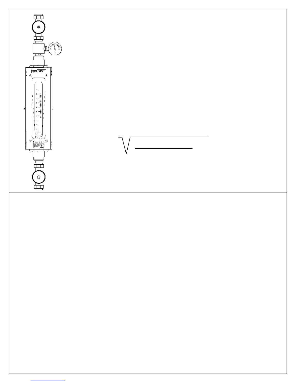
CLEANING
1) Carefully remove meter from the plumbing system. Before this is done make certain that the
system is properly secured, that the system pressure is O psi, and that the system is properly drained
down. In addition take whatever precautions are necessary to prevent injury to personnel in contact with
system fluid. See "WARNING" at bottom of this page.
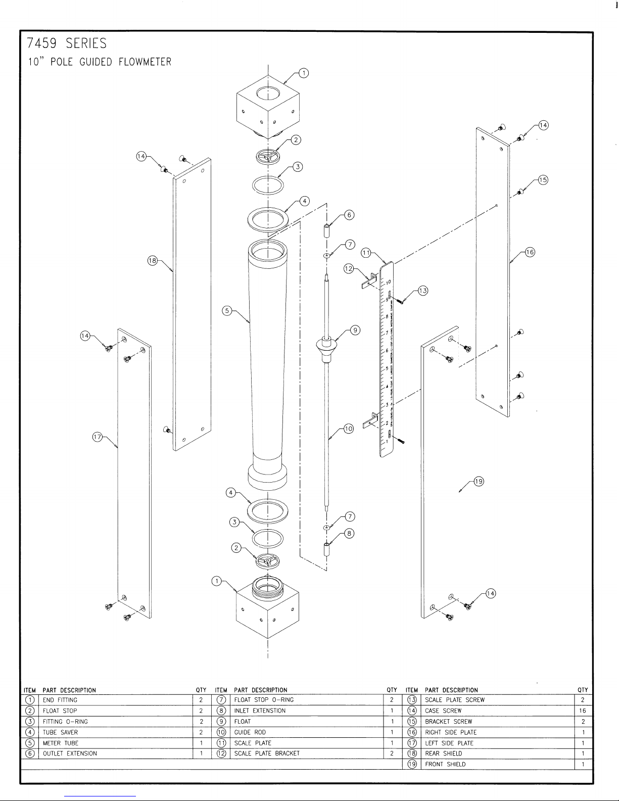
2) If the tube is plain taper (has a rod guided float) thread the extractor tool onto the threaded guide
extension in the outlet fitting. Remove the float stop retainers, and carefully withdraw the float and guide
assembly from the tube. The tube is now fully accessible for cleaning with a bottle brush and an appropriate
mild soap solution*. (It is normally not necessary to remove the inlet float stops when tubes have rod
guided floats.) The guide and float assembly may be cleaned with the same fluid. (This is not meant to
be disassembled.) To reassemble the meter, carefully guide the float assembly back into the tube.**
Line up the dimples on the float stop with threaded holes, insert and thread the float stop retainers into
the fitting. Tighten them down. Disengage the extractor tool. Remove and replace the Teflon tape on
the fittings. Reinstall meter into plumbing system.
3) If the tube is ribbed (i.e. fluted or beaded) thread the extractor tool onto the inlet float stop assembly
and remove the inlet float stop retainer screws. Gently extract the float stop from the fitting cavity. Use
care. The float will follow the stop out of the cavity. Remove the top float stop in the same fashion. The
tube is now ready for cleaning (as indicated above). When reassembling use caution as the float enters
the tube. The tube will be easily damaged if a cocked float is forced against the glass tube. When the
float and inlet stop are reinserted in the meter rotate the extractor tool to line up the float stop dimples and
the threaded float stop retainer holes. Reinsert the retainer screws and tighten. Disengage the extractor
tool. Repeat this last step on the outlet float stop assembly. Change the Teflon tape on the fittings and
reinstall meter into plumbing system.
*Do not use cleaning agents that will damage float, tube or O-rings.
** When installing float/guide assembly make certain that the end of the guide fully engages the inlet float
stop before retainer screws are replaced.
WARNING:
Pressure and temperature ratings are based on a study of the engineering data for particular materials
used in construction and on the design of individual models. This information is supplemented by
destructive test results. Meters with stainless enclosures must never be operated without shields securely
in place. Meters exposed to difficult environments such as those created by certain chemicals, excessive
vibration or other stress inducing factors could fail at or below the suggested maximums. Never operate
meters above pressure and temperature maximums. It is strongly recommended that all meter installations
utilize an appropriate pressure relief valve and/or rupture disc. The pressure settings and locations of
these devices should be such that meters cannot be overpressurized. Meter failure could result in
damage to equipment and serious personal injury. Always use suitable safety gear, including OSHA
approved eye protection when working around meters in service. We are happy to pass along chemical
compatibility information that has been published by the manufactures of raw materials used in our
products; however, this information should not be construed as a recommendation made by King Instrument
Company, Inc. for a specific application.