7
TO POOL
PUMP
FILTER
TOOLS NEEDED
Screwdriver
Pipe Wrench
Materials Needed
Pipe Thread Tape
or Sealant
Two hose adapters
1 1/2” x 1 1/2” x 1 1/4”
Two Sections of 1 1/2”
Flex Hose (one provided
with filter)
Two
Hose
Clamps
Recommended
Corrosion Resistant
Check Valve
4-8 psi Back Pressure
To avoid over or under chlorination,
replace eye ball fittings in the return
jets to a smaller or larger size to
adjust back pressure.
10 x 1 1/4” Phillips
Pan Head Screws with
Washers
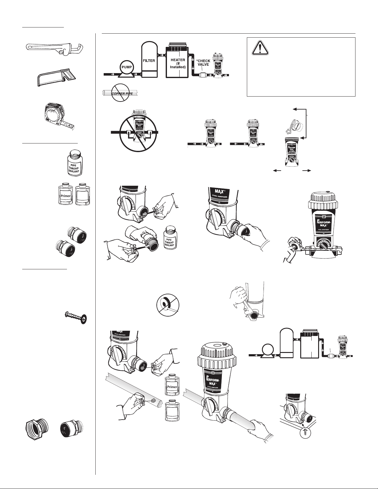
Apply pipe thread tape or
sealant to the threaded end of
both hose adapters.
1.
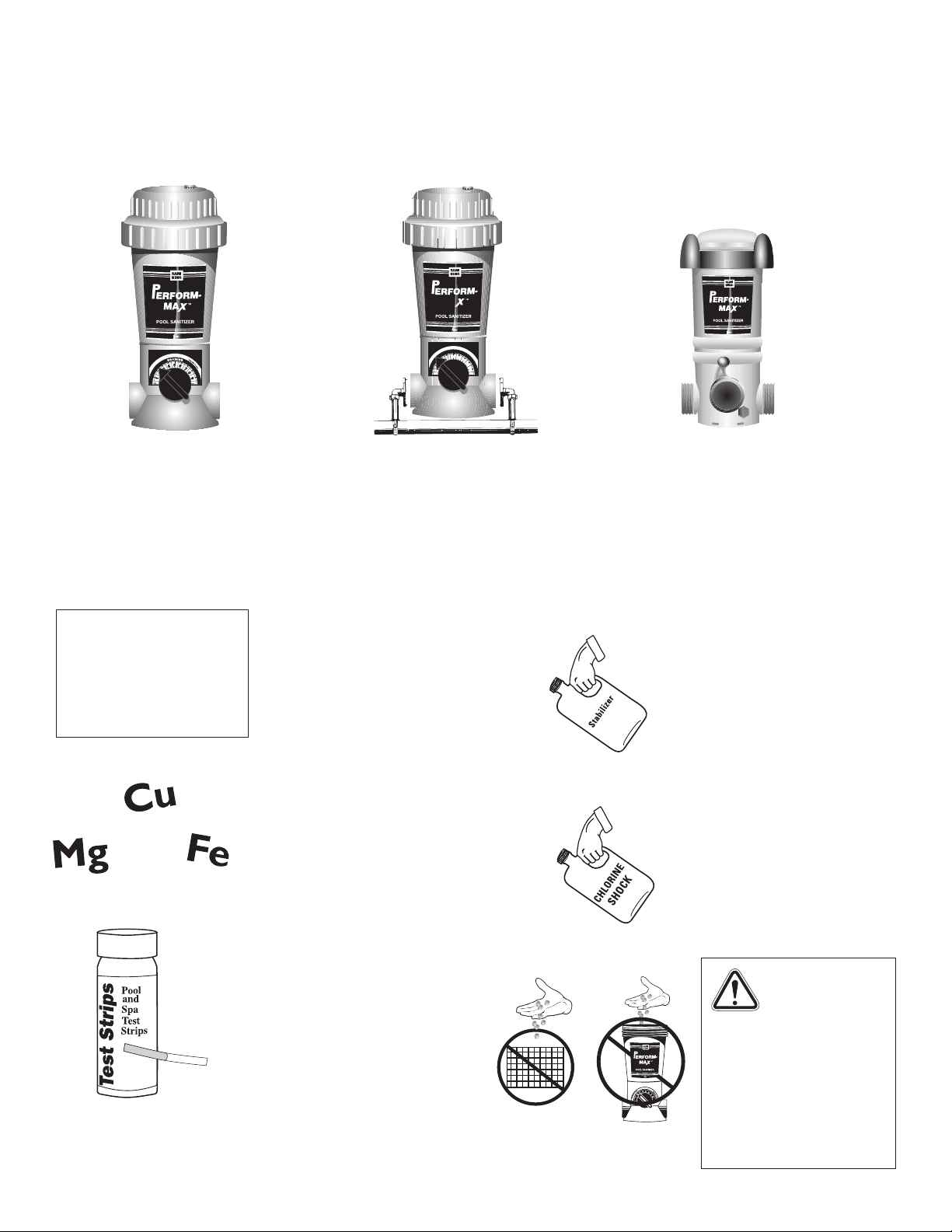
The Perform-Max should always be installed
between the filter and pool (or between heater
and pool if applicable).
Above Ground, Base Installation - Model 920
Screw adapters into each end of
Perform-Max Hand tighten. Finish
tightening by turning 1 to 2 revolutions
with wrench.
DO NOT OVER TIGHTEN.
2.
Attach the filter section of flex hose to one hose
adapter and the return section of flex hose to the other
hose adapter with clamps and tighten with screwdriver.
Bi-flow valve design allows water flow in either direction.
3.
Isolating the Perform-Max by installing a corrosion
resistant check valve is recommended.
4.
If you prefer to mount this
unit there is an additional
base part available - PN#
01-22-1480. Mount using
Phillips Pan head screws.
One in front and two in
back.
5.
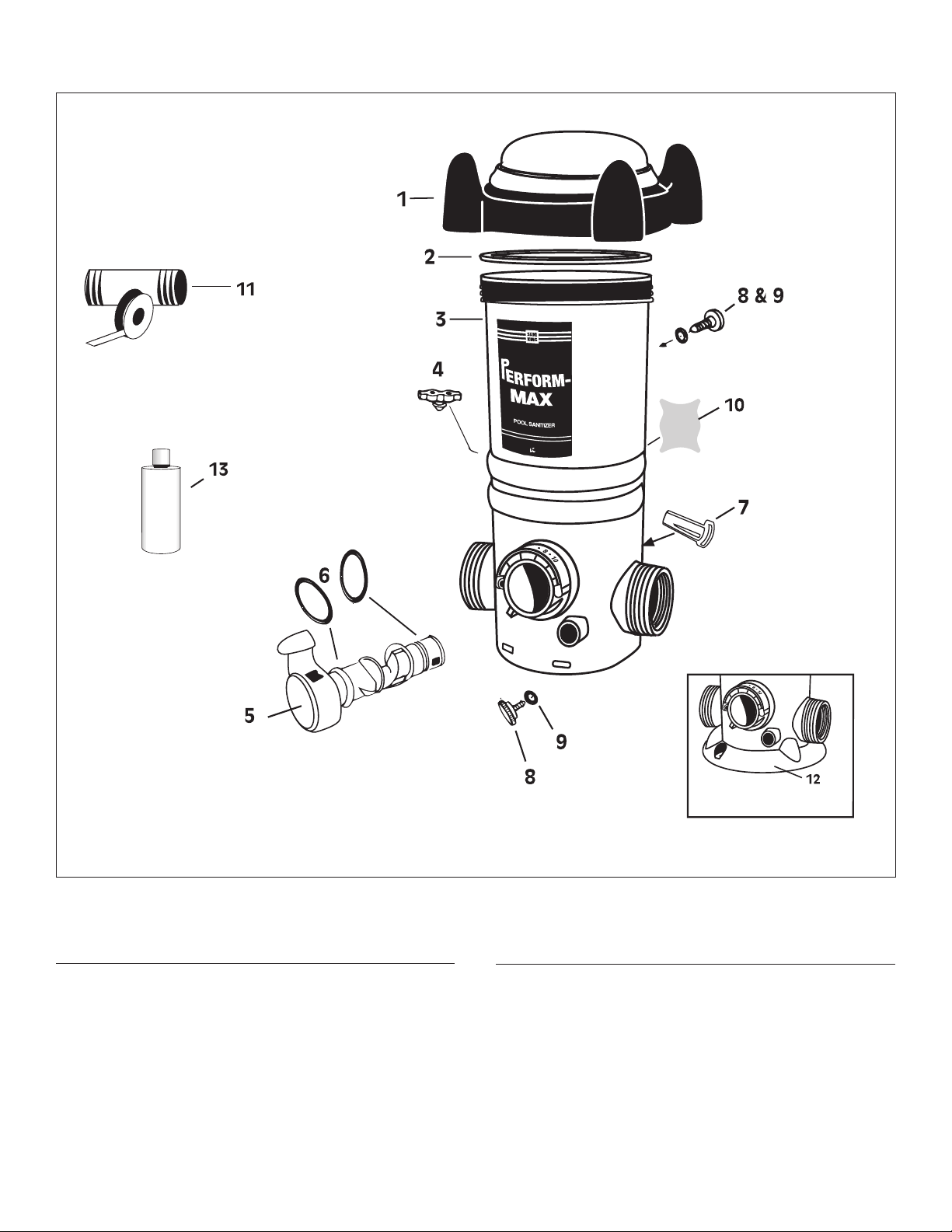
REPLACEMENT PARTS • Model 960
REF. # PART NUMBER DESCRIPTION
11 01-22-9490 2” Male Adapter
12 01-22-8620 2” X 1/2” Bushing
13 01-22-7800 90 Degree Elbow
14 01-22-7690 Small Clamp
15 01-22-7700 6’ PVC Tubing
16 01-22-7850 Scoop Gasket
17 01-22-7790 Venturi Scoop
18 01-22-7910 Scoop Clamp
Option
1 1/2” Male Adapter
(slip x MPT)
or
2” Female Adapter
(slip x FPT)
When installing with hard
PVC pipe, use either a female
adapter on the outside port
threads or a male adapter on
the inside port threads.
CHECK
VALV E
BUSHING
HOSE
CLAMP
HOSE
ADAPTER HOSE
CLAMP
HOSE
ADAPTER
TO POOL
1 1/2" OR 1 1/4"
FLEX HOSE
1 1/2" x 1 1/2" x 1 1/4"
HOSE ADAPTER
HOSE
CLAMP
FILTER &
PUMP
• Install after all equipment and
as far as possible from heater.
• Any additional sanitizing
equipment that is installed with
Perform-Max must be installed after
Perform-Max (never before) on the
return line to the pool.