ASSEMBLY and INSTALLATION connued...
2
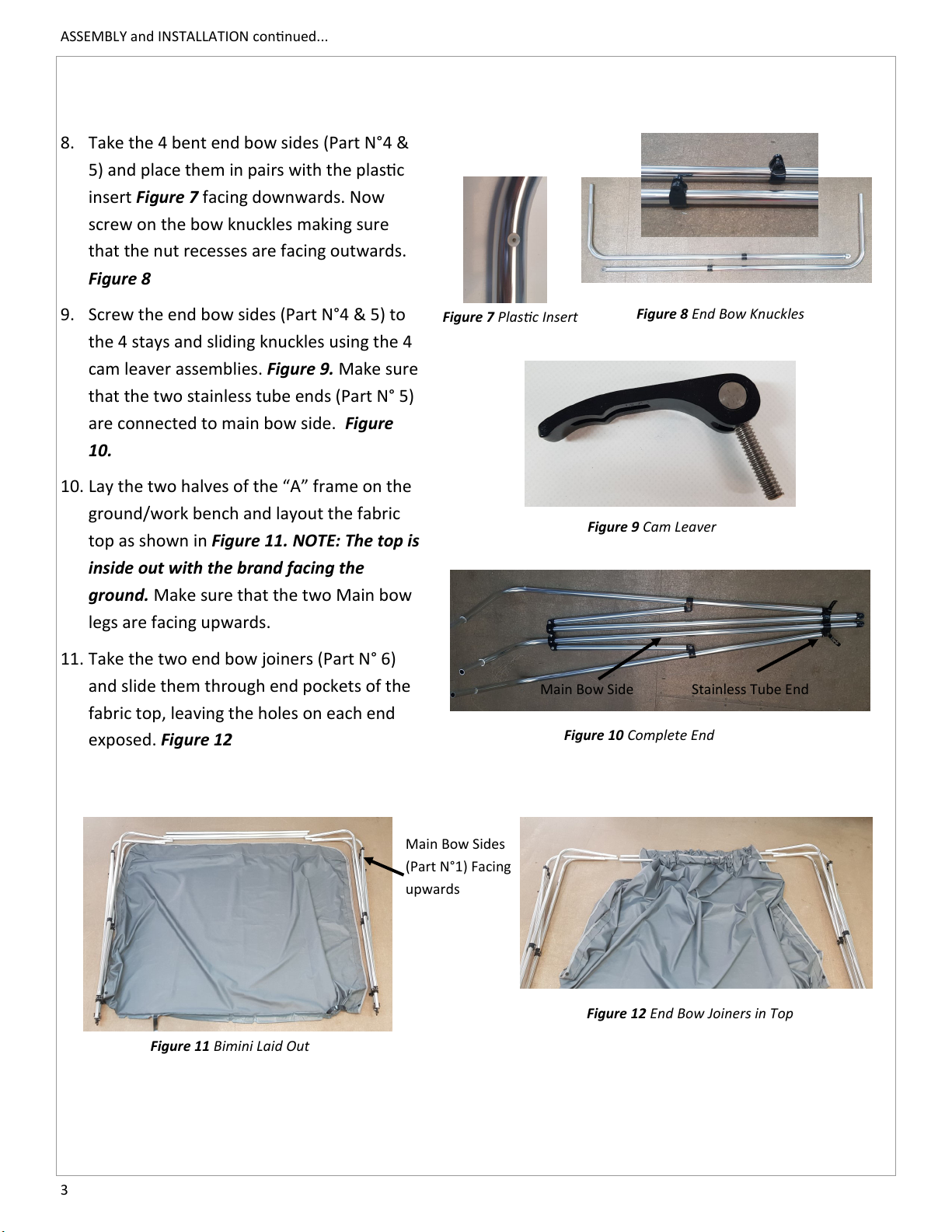
FRAME ASSEMBLY:
1. Locate all of the Frame components
(Part N° 1,2 ) Figure 1
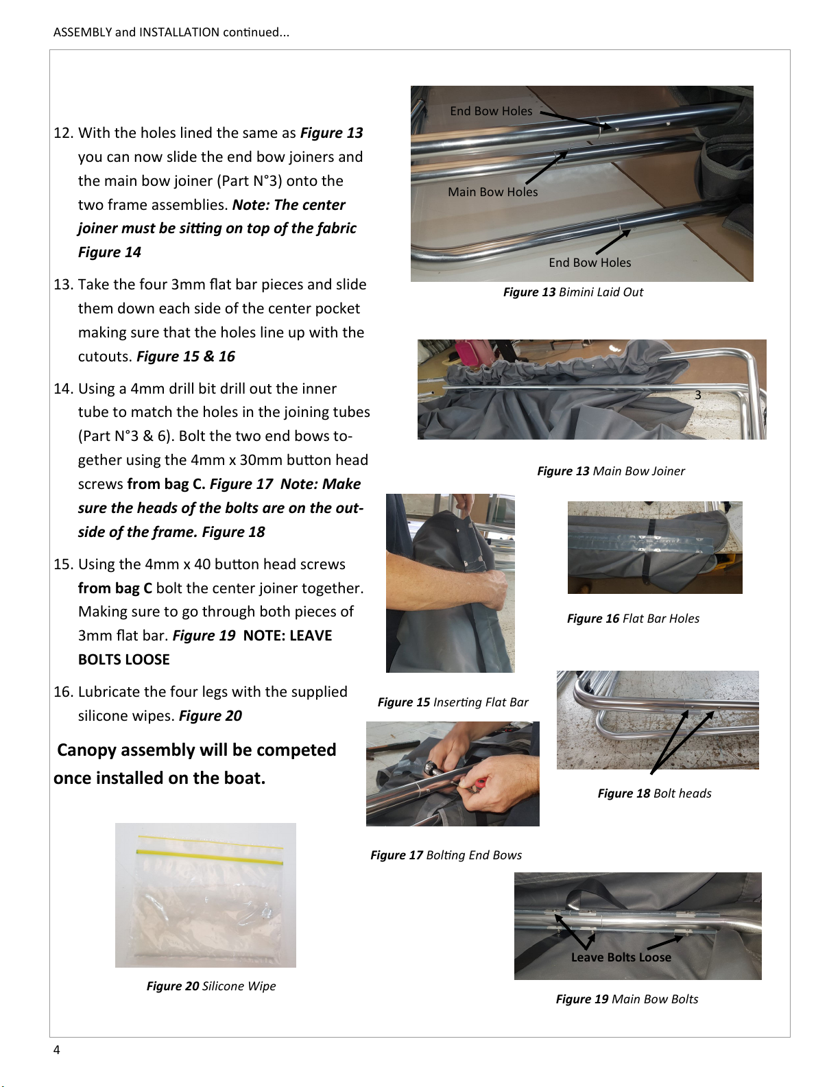
2. From bag A containing the black
plasc parts remove the four joining
knuckles. Using the 8G x 1/2” pan-
head, screw the joining knuckle
marked “A” (Figure 2) To each of the
bent main bow pieces (Part N° 1)
making sure that the nut recess is
facing outward and the screw head
is inwards. (Figure 3) NOTE: The holes
might need to be drilled out with a
3.5mm drill bit.
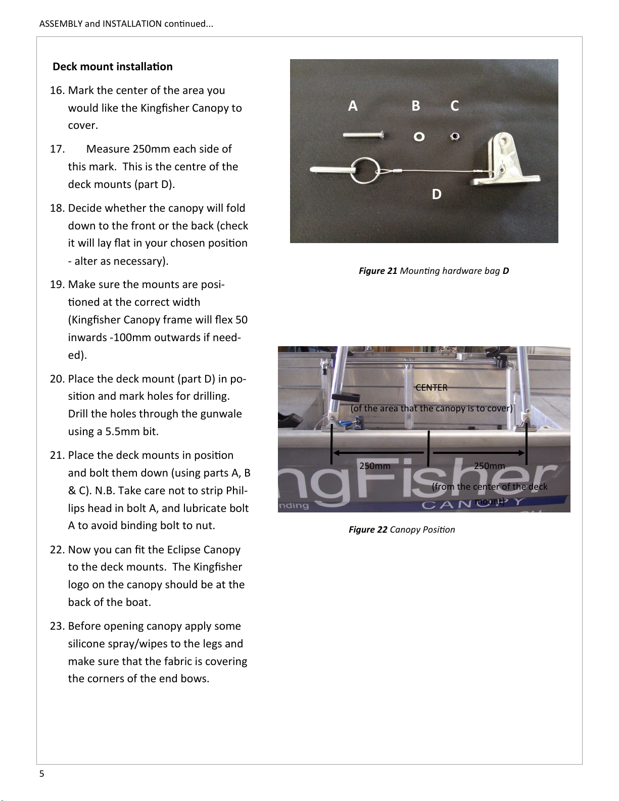
4. Aach the joining knuckles labeled
“B” (Figure 2) to the top of the
straight components. (Part N°2)
(Figure 3 & 4) Making sure to line up
the hole in the knuckle with the pre
drilled hole in the aluminum tube
and that the nut recess is facing out-
ward. You should have a mirror pair
of canopy ends. Figure 4
5. Screw the four plasc press studs to
the out side of the main bow legs
using the supplied countersunk 8G
screws. Figure 5
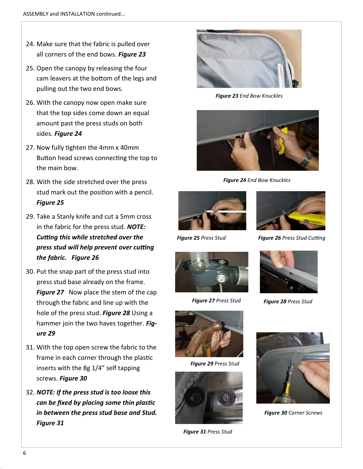
6. Screw the 4 stays (Part N° 7) to each
joining knuckle.
You should now have two halves
which look the same as Figure 6
7. Slide on the 4 sliding knuckles to the
boom of the legs (Part N° 1 & 2)
with the nut recesses facing out-
wards. Figure 6
Figure 1 Frame components.
11
2
2
Figure 2 Joining Knuckles
A
B
Figure 3 “A” Frame and Joining
knuckles
Figure 5 Stayput Press Studs
Figure 6 Complete Frame End
Stays
Sliding Knuckles
Figure 4 Frame Ends