Sleipner Side-Power ESPE 600 User manual

Page 1 5086-2-2018
Installation
and
User manual
ELECTROHYDRAULIC
POWER STEERING
SYSTEMS MK. III
ESPE 600
ESPE 700
Made in Norway
©Sleipner Motor AS 2018
SLEIPNER MOTOR AS
P.O. Box 519
N-1612 Fredrikstad
Norway
Document id: 5086
Revision: 2

5086-2-2018
Page 2
Contents
Please read this installation manual thoroughly, before you start
installing your Steering Power hydraulic steering kit.
Sleipner Motor AS will not take any responsibility for products that
are not installed in accordance with the instructions given in this
installation manual.
Important user precautions and procedures............................................................................................. 3
System layout, Flybridge (Twin helm) ...................................................................................................... 4
System layout, Non - Flybridge (Single helm) ......................................................................................... 5
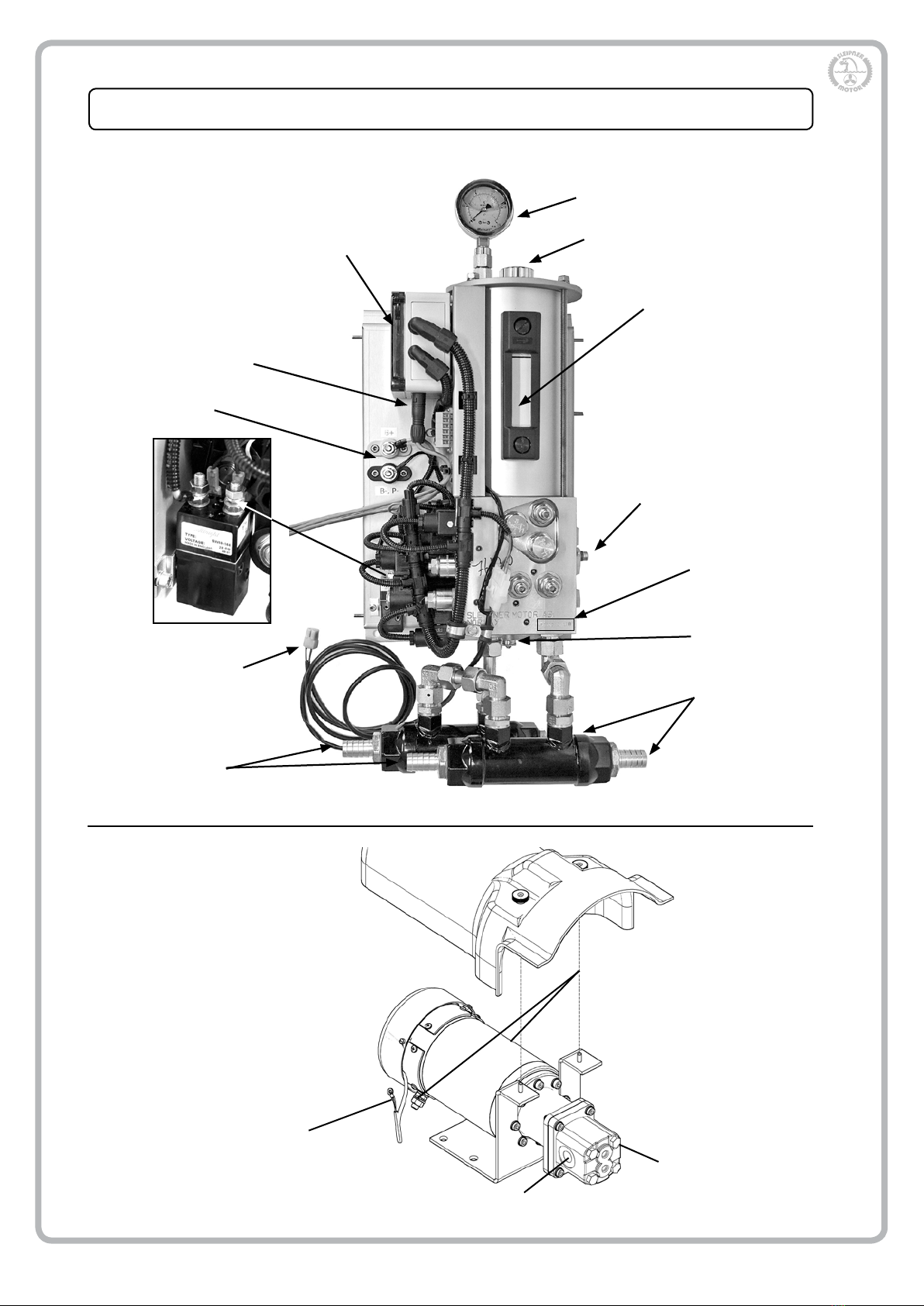
System Unit/ Servo Pump overview ......................................................................................................... 6
System Unit/ Servo Pump installation ...................................................................................................... 7
Hose installation .......................................................................................................................................
7................................................................................................................................................................
Hose connection....................................................................................................................................... 7
Power supply and signal cable connections ............................................................................................ 7
System Unit hydraulic ports...................................................................................................................... 8
Rudder Cylinder installation...................................................................................................................... 9
Helm Pump installation, Tilt pump with hydraulic backup......................................................................... 10
Helm installation, Tilt helm without hydraulic backup.. ............................................................................. 11
Tilt Helm steering friction adjustment ....................................................................................................... 11
Helm Pumps, hydraulic connections ........................................................................................................ 12
Filling & Air purging................................................................................................................................... 13
Hydraulic system ......................................................................................................................................
14..............................................................................................................................................................
Wiring diagram, Flybridge (Twin helm)..................................................................................................... 15
Wiring diagram, Non - Flybridge (Single helm) ........................................................................................ 16
Cooling system......................................................................................................................................... 17
ECU (Electronic control unit) .................................................................................................................... 18
Important installation precautions............................................................................................................. 19
Maintenance............................................................................................................................................. 19
Spare parts............................................................................................................................................... 21
All Side-Power steering products complies with
the CE directive 94/25/EC

Page 3 5086-2-2018
IMPORTANT USER PRECAUTIONS AND PROCEDURES
- Please take time to acquaint yourself with the Power steering system components, operation
characteristics and safety features.
- Should the helm pump warning light illuminate or the alarm sound, immediately reduce engine power
to idle and go to the helm position with hydraulic back up (Lower helm on Flybridge boat).
When carrying out any servicing work on the Power Steering System or removal of the systems
Oil Tank Filler Cap release the system pressure.
(Invert the air pressure valve dust cover and press it against the top of the pressure valve)
- The power steering system can have two types of helm pumps installed - with or without hydraulic
backup.
- The system will shut down immediately in the event of an unexpected major component failure related
to the safe operation of the system. Oil or electric motor overheat conditions will activate the helm
pump warning light and alarm sounder, the system will monitor the alarm condition for a further two
minutes before system shut down. If the alarm condition is resolved within 2 minutes the system will
continue to function normally.
- In the event of system shut down, the helm pump with hydraulic back up function will become the
only operational helm (the electric only helm unit will not function) the steering system will function as
normal but with an increased number of wheel turns accompanied by a heavier wheel feel.
Do not continue to drive the boat at high speeds using the back up system.
Cylinder bypass:
To centralize the rudders, release valve locknut, open valve NV3 & NV4 (turn ccw
until stop).The cylinder is now free and the rudders can be centralized. Return NV3
and NV4 to original closed position (cw until stop) and tighten valve locknut
- immediately reduce engine
power to idle, and go to the
helm position with hydraulic
backup!
IN THE EVENT OF SHUTDOWN
!

5086-2-2018
Page 4
System description for Flybridge Yachts (Twin helm)
Upper helm
Lower helm pump
Servo pump
System unit
Rudder cylinder
The Power steering system comprises four main components.
1) The System Unit, consists of the Electronic Control Unit (ECU), an Oil lter and a
Valve Block integrated with the Oil Tank (Reservoir).
2) A Hydraulic Pump Unit, driven by an attached 24volt D.C. electric motor.
3) 2 x Helm Pumps
4) Hydraulic Cylinder(s)
The lower (primary) steering position helm has two functions:
a) It contains electronic sensors which transmit a signal to the ECU for normal Steering
operation.
b) It acts as a Hydraulic Helm Pump (back-up) in the event of an ECU system shut
down (NB, The number of wheel turns will increase from stop to stop during back up
mode).
The upper/ybridge helm has electronic sensors that pulses signals to the ECU for
normal Steering operation.
Both helms have a built in warning LED (Red). This will illuminate during an alarm
condition.
See description of the alarm functions on page 3
Hydraulic connections
Electric connections Alarm buzzer
Alarm buzzer

Page 5 5086-2-2018
System description for Non Flybridge Yachts (Single helm)
Helm pump
Servo pump
System unit
Rudder cylinder
Hydraulic connections
Electric connections
Alarm buzzer
The Power steering system comprises four main components.
1) The System Unit, consists of the Electronic Control Unit (ECU), an Oil lter and a
Valve Block integrated with the Oil Tank (Reservoir).
2) A Hydraulic Pump Unit, driven by an attached 24volt D.C. electric motor.
3) 2 x Helm Pumps
4) Hydraulic Cylinder(s)
The lower (primary) steering position helm has two functions:
a) It contains electronic sensors which transmit a signal to the ECU for normal Steering
operation.
b) It acts as a Hydraulic Helm Pump (back-up) in the event of an ECU system shut
down (NB, The number of wheel turns will increase from stop to stop during back up
mode).
The upper/ybridge helm has electronic sensors that pulses signals to the ECU for
normal Steering operation.
Both helms have a built in warning LED (Red). This will illuminate during an alarm
condition.
See description of the alarm functions on page 3

5086-2-2018
Page 6
System Unit/Servo Pump overview
Inlet (3/8” BSP)
Outlet (3/8” BSP)
Temperature
sensor
(connects to
System Unit)
SERVO PUMP UNIT
Power (from System Unit)
SYSTEM UNIT
Coolers
Pressure gauge
ECU Filler cap
Oil level gauge
Hydraulic connections
for helm pump(s),
rudder cylinder and
servo pump
Power terminals
Signal connections, helm
pumps and alarms
Pressure
test point
Temperature sensor
connection to servo
pump unit Water in
Water out
B+
B-, P-
P+ Serial number

Page 7 5086-2-2018
Serial number
System Unit/Servo Pump installation
- Locate a suitable position to install the System Unit and Servo Pump Unit. Make sure that the selected
mounting position is adequate to support the system unit (approx 25 kg) and servo pump (approx. 10 kg)
- Mount the system unit and servo pump.
- Clean and ush all hoses. Use plastic caps or tape to seal the hose ends before the hoses are installed.
- When routing the hoses, avoid restrictions, hot spots, sharp edges and tight bends (Rmin = 130 mm
for 3/8” hose and 180 mm for ½” hose). Secure hoses with appropriate fastening devices to avoid
chang.
Hose installation
- Connect the servo pump hydraulic inlet/suction hose to hydraulic port S on the system unit. Connect
servo pump hydraulic outlet/pressure hose to hydraulic port P (lter) on system unit. Please refer to
drawing on page 8 for hydraulic port layout on the system unit.
- The Hoses can be connected either vertically or horizontally into the helm pump
(see helm pump description)
- Connect the hoses to the helm pump and the cylinder according to drawing on page 8 and 12.
- Connect the cooling water inlet/outlet hoses to the engine cooling system. Ensure that the hoses are
installed in accordance with this manuals paragraph “Hose Installation”.
Hose connecting
- Connect the temperature sensor leads to the system unit (external contacts). Connect the power leads
from (B-,P-) to Servo Pump (-), and (P+) on system unit external relay to (+) on Servo Pump.
- Connect battery power (24V DC) to the System Unit power terminals (positive cable to (B+) terminal
and negative to (B-) terminal & torque load to 17Nm)
- A 50Amp fuse must be installed in proximity of the batteries on the positive cable run, to protect the
system from damage from possible short circuiting.
For schematic drawings , see page 15 (Twin helm) & page 16 (Single helm).
- Connect the “Motor On” and Pilot Signal electrical looms to the external terminal block mounted on the
System Unit.
Power supply and signal leads connecting
Secure cables properly to attachment
points with cable ties
Pilot STB
Pilot GND
Pilot PRT
Joystick STB
Joystick GND
Joystick PRT
Engine 2
Engine GND
Engine 1
ECU external connector layout

5086-2-2018
Page 8
P1
P2
T
T1
S
A
BP
P1: 1/4” BSP - Helm pump pressure port A
P2: 1/4” BSP - Helm pump pressure port B
T: 1/4” BSP - Helm pump upper drain port
T1: 1/4” BSP - Helm pump lower drain port
S: 1/2” BSP - Servo pump, hydraulic inlet / suction
P: 1/2” BSP - Servo pump, hydraulic outlet / pressure
A: 1/4” BSP - Rudder cylinder stb feed / port return
B: 1/4” BSP - Rudder cylinder port feed / stb return
System Unit hydraulic ports

Page 9 5086-2-2018
- The Cylinder must be mounted on a solid, rigid surface, either directly to the hull, or using an suitable
bracket.
- The Cylinder should be angled parallel to the transom (or to the tie bar on dual rudder installations),
when the rudder is at one of its end stops.
Ensure the cylinder stroke has been set to half full travel when the rudders are “dead ahead” , this
ensures equal stroke in both directions. - The cylinder must be installed in a position where the stroke
will be equal in both directions
- Secure the cylinder mounting foot with bolts, washers and Locknuts (i.e. Nyloc).
- It is important that the cylinder mounting foot is installed 90 degrees to the tiller arm, when the rudder
is in its centre position.
- Connect the cylinders rod end to the tiller arm using the correct sized bolt.
- Tighten the bolt.
- Connect the hydraulic hoses to the cylinder referring to schematics on page 9 and 14.
Rudder Cylinder installation
PART A B C D E 1 2
71140P190 190 155 269 204 556.5 1/4” BSP 1/4” BSP
71220P190 190 158 302 207 573.5 3/8” BSP 3/8” BSP
71220P220 220 180 332 237 633.5 3/8” BSP 3/8” BSP
Page 9 Version 2.4 2008
- The Cylinder must be mounted on a solid, rigid surface, either directly to the hull, or using an appropri-
ate bracket.
- The Cylinder should be angled parallel to the transom (or to the tie bar on dual rudder installations),
when the rudder is at one of its end stops.
Ensure the cylinder stroke has been set to half full travel when the rudders are “dead ahead” , this
ensures equal stroke in both directions. - The cylinder must be installed in a position where the stroke
will be equal in both directions
- Secure the cylinder mounting foot with bolts, washers and Locknuts (i.e. Nyloc).
- It is important that the cylinder mounting foot is installed 90 degrees to the tiller arm, when the rudder
is in its centre position.
- Connect the cylinders rod end to the tiller arm using the correct sized bolt.
- Tighten the bolt.
- Connect the hydraulic hoses to the cylinder referring to schematics on page 9 and 14.
Rudder Cylinder installation
PART A B C D E 1 2
71140P190 190 155 269 204 556.5 1/4” BSP 1/4” BSP
71090P170 170 161.5 252 210.5 503.5 1/4” BSP 1/4” BSP
71090P190 190 181.5 272 230.5 543.5 1/4” BSP 1/4” BSP
71220P190 190 158 302 207 573.5 3/8” BSP 3/8” BSP
71220P220 220 180 332 237 633.5 3/8” BSP 3/8” BSP
A
B C
D E
1 2

5086-2-2018
Page 10
- Ensure there is adequate space to install the Helm Pump, Steering Wheel, associated looms and
hoses. Check they do not interfere with cables, wires or other components (See the helm pump
dimensions)
- Cut a hole (Ø121 mm), and drill the four 7 mm (5/16”) screw holes in accordance with the
dimensioned drawing.
- Fit the helm ttings and connect the hydraulic hoses referring to the diagram on page 12.
- Secure the helm pump using the washer and nuts (6mm).
- Apply a thin layer of grease on the helm pump shaft & t the steering wheel.
Connect signal and alarm cables. Refer to page 15 (Twin helm boats) and page 16 (Single helm boats).
Secure and fasten helm unit wiring to avoid wire and connector tension sharp obstacles and chang.
NOTE: Ensure “dummy” plug is tted to the Helm B port on single helm boats.
Tilt Helm pump installation – Electric & hydraulic backup
1
1
2
2
3
3
4
4
5
5
6
6
A A
B B
C C
D D
72063
12/15/2016
1
Designed by Date
1/1
Edition Sheet
Elvira H.
Material Type Drawing nr
02-00-010-168
Copyright All rights reserved
Part nr Size Scale
Title Rattpumpe 42ccm
Tolerance NS-ISO 2768-1
SLEIPNER MOTOR AS
A3
3.002 kg 1:2
Weight
131,5 47 55
233
121
ØCut out / utkjæring
17
5°
96
127
96
127
Upper Drain Port
Øvre Drenport
Horizontal Pressure Port
Horisontal Trykkport
Horizontal Pressure Port
Horisontal Trykkport
Lower Drain Port
Nedre Drenport
Vertical Pressure Port
Vertikal Trykkport
Vertical Pressure Port
Vertikal Trykkport
Filling Cap
Påfyllingsplugg
Key
Kile
1
1
2
2
3
3
4
4
5
5
6
6
A A
B B
C C
D D
72068
12/15/2016
1
Designed by Date
1/1
Edition Sheet
Elvira H.
Material Type Drawing nr
SM-101892
Copyright All rights reserved
Part nr Size Scale
Title Rattpumpe 35ccm
Tolerance NS-ISO 2768-1
SLEIPNER MOTOR AS
A3
2.943 kg 1:2
Weight
Uten flens
59
52
120 55
233
90
ØCut out (utkjæring)
Filler Cap
(Påfyllingplugg)
Key
(kile)
17
5°
72
72
M6x60 (x4)
Upper Drain Port
(Øvre Drenport)
Horizontal Pressure Port
(Horisontal Trykkport)
Horizontal Pressure Port
(Horisontal Trykkport)
Lower Drain Port
(Nedre Drenport)
Vertical Pressure Port
(Vertikal Trykkport)
Vertical Pressure Port
(Vertikal Trykkport)
120
#72061
#72062
#72063
#72064
#72065
#72066
1
1
2
2
3
3
4
4
5
5
6
6
A A
B B
C C
D D
74085
19.12.2016
1
Designed by Date
1/1
Edition Sheet
Elvira H.
Material Type Drawing nr
SM-101897
Copyright All rights reserved
Part nr Size Scale
Title Rattpumpe m/tilt/sensor 35ccm
Tolerance NS-ISO 2768-1
SLEI PNER MOTOR AS
A3
3,784 kg 1:2
Weight
Elektr.pumpe
9
6
1
3
3
96
13
3
99
M6 (x4)
Upper Drain Port
(Øvre Drenport)
Lower Drain Port
(Nedre Drenport)
Horizontal Pressure Port
(Horisontal Trykkport)
Horizontal Pressure Port
(Horisontal Trykkport)
121
ØCut out (utkjæring)
131
45 77
5°
17
Ø
-10
/0
/10
/20
/35
Key
(Kile)
#72067
#72068
#72069
Vertical Pressure Port
Vertikal Trykkport
Vertical Pressure Port
Vertikal Trykkport

Page 11 5086-2-2018
Tilt Helm installation - Electric only
- Ensure there is adequate space to install the Helm Pump, Steering Wheel, associated looms and
hoses.Check that they do not interfere with cables, wires or other components (See the helm pump
dimensions)
- Cut a hole (Ø121 mm), and drill the four 7 mm (5/16”) screw holes in accordance with the dimen-
sioned drawing.
- Secure the helm pump using the washer and nuts (6mm).
- Apply a thin layer of grease on the helm pump shaft & t the steering wheel.
Connect signal and alarm cables. Refer to page 15 (Twin helm boats) and page 16 (Single helm boats).
Secure and fasten helm unit wiring to avoid wire and connector tension sharp obstacles and chang.
NOTE: Ensure “dummy” plug is tted to the Helm B port on single helm boats
Helm Unit steering friction adjustment
The steering friction setting has a pre-set
standard value from manufacture. The friction can be adjusted
to a preferred setting as follows:
- Remove the plastic plug in the end cover using a Screwdriver.
(Pict.1)
- Using a 2.5 mm Allen Key adjust as follows: (Pict.2)
o Turning clockwise increases the friction
o Turning counter-clockwise reduces the friction
Check for desired friction after every ½ turn.
- When satised with friction setting, re-t the plastic plug.
Pict. 1
Pict. 2
Yacht_steering_manual2016
2
1.1
Snapshot
Yacht_steering_manual2016
2
1.2
Snapshot

5086-2-2018
Page 12
Helm Pump - Hydraulic connections
A: 1/4” BSP - Helm pump pressure port A
B: 1/4” BSP - Helm pump pressure port B
X2: 1/4” BSP - Helm pump upper drain port
X1: 1/4” BSP - Helm pump lower drain port
X2
AB
X1
B
A
P1: 1/4” BSP - To helm pump pressure port A
P2: 1/4” BSP - To helm pump pressure port B
T: 1/4” BSP - To helm pump upper drain port
T1: 1/4” BSP - To helm pump lower drain port
Helm pump System unit
P1
T1
P2
T

Page 13 5086-2-2018
Filling & Air purging
FILLING AND BLEEDING PROCEDURE
NOTE!
Always ensure that the Servo System
(tank) Pressure is released before
removing the Tank Filler Cap.
(See IMPORTANT USER PRECAU-
TIONS AND PROCEDURES)
- Fill the tank with hydraulic oil ISO-
VG-15 (DIN51524-3 HVLP specica-
tions), Ensure that the oil is clean
(use a lling lter).
- Set Servo Unit valves to:
NV1: Closed (turn CW to stop)
NV2: Open (turn CCW to stop)
NV3: Open (turn CCW to stop)
NV4: Open (turn CCW to stop)
- Switch ‘ON’ the main power to the Servo Unit.
- Set the Ignition switch to “ON” or activate
Engine Override Switch to “UP” (Switch no.2),
in the ECU Control Box (page.18)
- Run the pump for 3 minutes by operating the
Pump Override Switch (position “UP”) (Switch
no.1). If the oil level falls below the Level
Gauge during bleeding, replenish the oil. NB:
Larger yachts require several replenishments
of the tank during bleeding.
- Pressurize the tank to 1.5 bar with the supplied
air pump (bicycle).
- Wait for 3 minutes
- Turn the steering wheel at the lower steering
position (Helm hyd/electric Pump) 20 revolu-
tions to Port, then 20 revolutions to Starboard.
- Reset Servo Unit valves to their initial positions
NV1: Open (turn CCW to stop) NV2: Closed (turn CW to stop)
NV3: Closed (turn CW to stop) NV4: Closed (turn CW to stop)
- Deactivate Servo System By switching ‘OFF’ the Ignition Switch, Engine Override Switch (Switch no.2)
and Pump Override Switch (Switch no.1).
NB. The steering system now will act as a normal hydraulic steering and will be heavier to operate.
- Finally, rotate the Steering Wheel to one of its end stops and hold with pressure against the
stop, for approximately 5 sec. Carry out this procedure in the opposite direction.
Repeat this procedure one more time in both directions.
- Check the system for signs of leakage.
- Replenish oil to upper half of the oil level gauge.
- Pressurize the tank to 1.5 bar with the supplied air pump (bicycle).
- Both the Pump Override Switch and the Engine ON switch must be set in the “down” position during
normal operations when the Main Engines are running.
NV1
NV2
NV4
NV3
Tank ller cap

5086-2-2018
Page 14
Hydraulic system
2121
Green
Brown
3-Wire
loom
Lower helm position.
Helm with sensors and hydraulic
backup.
+Alarm buzzer
Grey/Red
Black
2121-
White
Green
Brown
B+
B+
B-, P-
B+ B-
- (Black)
+ (Red)
oC
+
-
50 A
From system unit internal wiring
Red
Blue
Alarm lamp
From system unit
internal wiring
From system unit
internal wiring
Blue
Black
To system unit internal
wiring
Black
Red
White
2121
White
Green
Brown
3-Wire
loom
+
Red
Blue
Alarm lamp
Upper helm position
Helm with sensors and
el. brake.
Alarm buzzer
Grey/Red
Black
2121-
White
Green
Brown
White
Brown
+
-
3-Wire
loom
Helm A
Helm B
Alarm
Alarm

Page 15 5086-2-2018
Wiring diagram, Flybridge Yachts (Twin helm)
2121
Green
Brown
3-Wire
loom
Lower helm position.
Helm with sensors and hydraulic
backup.
+Alarm buzzer
Grey/Red
Black
2121-
White
Green
Brown
B+
B+
B-, P-
B+ B-
- (Black)
+ (Red)
oC
+
-
50 A
From system unit internal wiring
Red
Blue
Alarm lamp
From system unit
internal wiring
From system unit
internal wiring
Blue
Black
To system unit internal
wiring
Black
Red
White
2121
White
Green
Brown
3-Wire
loom
+
Red
Blue
Alarm lamp
Upper helm position
Helm with sensors and
el. brake.
Alarm buzzer
Grey/Red
Black
2121-
White
Green
Brown
White
Brown
+
-
3-Wire
loom
Helm A
Helm B
Alarm
Alarm
2121
White
Green
Brown
3-Wire
loom
2121
Green
Brown
3-Wire
loom
+
Red
Blue
Alarm lamp
Upper helm position
Helm with sensors and
el. brake.
Alarm buzzer
Grey/Red
Black
Lower helm position.
Helm with sensors and hydraulic
backup.
2121-
+Alarm buzzer
Grey/Red
Black
2121-
White
Green
Brown
White
Green
Brown
White
Brown
B+
B+
B-
P-
B+ B-
- (Black)
+ (Red)
oC
Helm A
Helm B
Alarm
Alarm
+
-
+
-
50 A
From system unit internal wiring
3-Wire
loom
Red
Blue
Alarm lamp
P+

5086-2-2018
Page 16
Wiring diagram, Non Flybridge Yachts (Single helm)
2121
Green
Brown
3-Wire
loom
Lower helm position.
Helm with sensors and hydraulic
backup.
+Alarm buzzer
Grey/Red
Black
2121-
White
Green
Brown
B+
B+
B-, P-
B+ B-
- (Black)
+ (Red)
oC
Helm A
Helm B
Alarm
Alarm
+
-
50 A
From system unit internal wiring
Red
Blue
Alarm lamp
Helm Dummy
From system unit
internal wiring
From system unit
internal wiring
Blue
Black
To system unit internal
wiring
Black
Red
White
2121
White
Green
Brown
3-Wire
loom
2121
Green
Brown
3-Wire
loom
+
Red
Blue
Alarm lamp
Upper helm position
Helm with sensors and
el. brake.
Alarm buzzer
Grey/Red
Black
Lower helm position.
Helm with sensors and hydraulic
backup.
2121-
+Alarm buzzer
Grey/Red
Black
2121-
White
Green
Brown
White
Green
Brown
White
Brown
B+
B+
B-
P-
B+ B-
- (Black)
+ (Red)
oC
Helm A
Helm B
Alarm
Alarm
+
-
+
-
50 A
From system unit internal wiring
3-Wire
loom
Red
Blue
Alarm lamp
P+

Page 17 5086-2-2018
W out W in
Cooling system

5086-2-2018
Page 18
ECU ( Electronic Control Unit)
Switches on ECU
1. PUMP OVERRIDE SWITCH
Switch position Down - Normal operation.
Switch position UP - Override Mode used for system air purging.
2. ENGINE ON OVERRIDE SWITCH
Switch position Down - Normal operation.
Switch position UP - Override Mode used for system air purging.
SWITCH 2
SWITCH 1
HELM A HELM B ALARM A ALARM B
Pilot STB
Pilot GND
Pilot PRT
Joystick STB
Joystick GND
Joystick PRT
Engine 2
Engine GND
Engine 1
(OPTIONAL)
(OPTIONAL)
(OPTIONAL)

Page 19 5086-2-2018
Maintenance
- All hydraulic components must be installed in a clean environment to avoid contamination
- All hose-ends and connection points should be sealed during the installation.
- Clean oil is of ultimate importance for reliable and trouble free operation in regards to all
hydraulic systems.
- Ensure that all bolts and connections are tightened and secure.
- Use Hydraulic Oil ISO-VG-15 (DIN51524-3 HVLP specications) ONLY.
- Keep all hoses and looms clear of sharp edges and hot surfaces.
- Hoses and looms must be secured adequately to prevent chang.
- Thoroughly purge system of air.
- Check for leaks.
- Operate the cylinder from end stop to end stop. Force the steering wheel 1/4 to 1/2 turn further
to build up the pressure in the system. Check for leaks.
On completion of installation perform a full functional test of all components including alarm l.e.d.
and sounders.
Sealing of Servo Steering System components
Only use the sealing components provided for the Servo Steering System by Steering-power. The
use of any unauthorised loctites, sealing compounds or components not provided by Steering-power
will disqualify warranty reclamation.
NOTE!
Always ensure that the system (tank) pressure is released before removing the tank ller cap.
Monthly:
- Check tank pressure ( Min: 1.25 Bar/18 PSI - Max. 2.0 Bar/29 PSI)
- Check the oil level - visible in the upper half of the level gauge.
NB - If the system oil level is low, carry out the following:
- Check thoroughly for system leakage & replenish as necessary.
6th Monthly:
- Check hoses and connections/ttings for leakages.
- Check hoses for damage (caused by sharp edges, hot surfaces etc).
- Check that all bolts are tightened and secure.
- Ensure that bearings and joints are lubricated and free to rotate
Yearly/every third year:
- The Hydraulic Oil and Filter require replacing after the rst years service,
and then consequently every third year there after.
- Check DC motor brush wear yearly
For further support, contact you dealer or other authorized service personnel.
Important installation precautions

5086-2-2018
Page 20
Warranty Statement
1. The equipment manufactured by Sleipner Motor AS (The “Warrantor”) is warranted to be free from defects in workmanship and materials under normal
use and service.
2. This Warranty is in eect for of two years (Leisure Use) or one year (Commercial use) from the date of purchase by the user. Proof of purchase must be
included, to establish that it is inside the warranty period.
3. This Warranty is transferable and covers the product for the specied time period.
4. In case any part of the equipment proves to be defective, other than those parts excluded in paragraph 5 below, the owner should do the following:
(a) Prepare a detailed written statement of the nature and circumstances of the defect, to the best of the Owner’s knowledge, including the date of
purchase, the place of purchase, the name and address of the installer, and the Purchaser’s name, address and telephone number;
(b) The Owner should return the defective part or unit along with the statement referenced in the preceding paragraph to the warrantor,
Sleipner Motor AS or an authorized Service Centre, postage/shipping prepaid and at the expense of the Purchaser;
(c) If upon the Warrantor’s or Authorized Service Centre’s examination, the defect is determined to result from defective material or workmanship, the
equipment will be repaired or replaced at the Warrantor’s option without charge, and returned to the Purchaser at the Warrantor’s expense;
(d) no refund of the purchase price will be granted to the Purchaser, unless the Warrantor is unable to remedy the defect after having a reasonable
number of opportunities to do so. Prior to refund of the purchase price, Purchaser must submit a statement in writing from a professional boating
equipment supplier that the installation instructions of the Installation and Operation Manual have been complied with and that the defect remains;
(e) warranty service shall be performed only by the Warrantor, or an authorized Service Centre, and any attempt to remedy the defect by anyone else
shall render this warranty void.
5. There shall be no warranty for defects or damages caused by faulty installation or hook-up, abuse or misuse of the equipment including exposure to
excessive heat, salt or fresh water spray, or water immersion except for equipment specically designed as waterproof.
6. No other express warranty is hereby given and there are no warranties which extend beyond those described in section 4 above. This Warranty is
expressly in lieu of any other expressed or implied warranties, including any implied warranty of merchantability, tness for the ordinary purposes for
which such goods are used, or tness for a particular purpose, and any other obligations on the part of the Warrantor or its employees and
representatives.
7. There shall be no responsibility or liability whatsoever on the part of the Warrantor or its employees and representatives for injury to any person or
persons, or damage to property, loss of income or prot, or any other consequential or resulting damage or cost which may be claimed to have been
incurred through the use or sale of the equipment, including any possible failure or malfunction of the equipment, or part thereof.
8. The Warrantor assumes no liability for incidental or consequential damages of any kind including damages arising from collision with other vessels
or objects.
9. This warranty gives you specic legal rights, and you may also have other rights which vary from country to country.
This manual suits for next models
1
Table of contents
Other Sleipner Boating Equipment manuals
Popular Boating Equipment manuals by other brands

Lofrans
Lofrans LION 1000 Installation and user manual

MINN KOTA
MINN KOTA MKR-26 manual

Basta Boatlifts
Basta Boatlifts Over-Center Replacement parts, Installation, Assembly

Hobie
Hobie Mirage Tandem instruction manual

Sea Ray
Sea Ray Sport Series Installation/Care

Tides Marine
Tides Marine SureSeal installation instructions