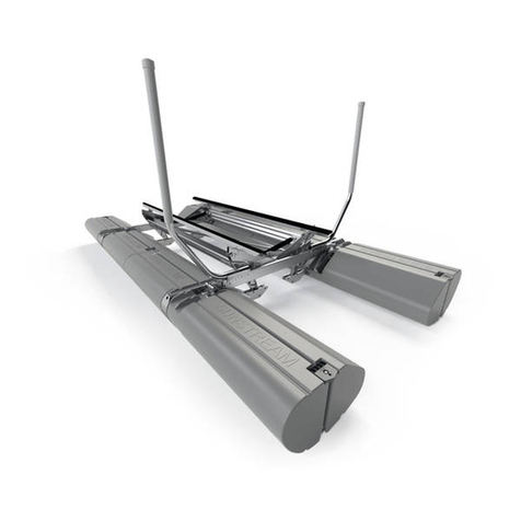
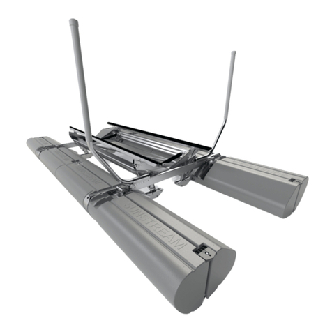
Sunstream FL-24020D User manual

PART NO. 690809 REV: A
FloatLift
24,000lbs-40,000lbs
OPERATION MANUAL
READ CAREFULLY
KEEP THESE INSTRUCTIONS
MODEL NUMBERS
FL-24020D
FL-36026D
FL-40026D
GFL-24020D
GFL –36026D
GFL-40026D
COPYRIGHT SUNSTREAM CORPORATION 2015—ALL RIGHTS RESERVED

PART NO. 690809 REV: A 2
Table of Contents
Disclaimer of Liability 2
Safety 3-4
Specifications 5-8
Parts List 9-16
Lift Installation 17-21
Lift Operation 22-25
Maintenance 26-28
Troubleshooting 29
Battery Wiring and Hydraulic Schematic 30-32
Inspection Forms 33-36
Many boats today require specific bunk/support configurations; Multi-hull boats, including but not
limited to pontoon, tritoon, some V-hull and catamaran style boats often require specific bunk con-
figurations to properly support the boat on a boatlift.
In some cases boat hull material and strake layout also may require “a custom engineered” bunk
configuration. Any boat on a Sunstream lift should be supported per boat manufacturer recom-
mendations.
Contact the boat manufacturer to verify how to support the boat. Sunstream is not responsible for
determining the proper way to support each craft that may go on a Sunstream lift.
Inadequate support or incorrect position of a boat on a Sunstream lift may result in damage to the
boat.
Sunstream does not warrant that any bunk/kit configuration will support the hull/sponsons as the
boat manufacturer intends or requires.
Disclaimer of Liability

PART NO. 690809 REV: A 3
Safety
Will result in serious injury or death.
Could result in serious injury or death.
Could result in minor or moderate injury.
Not related to personal injury
IMPORTANT SAFETY INSTRUCTIONS
If you have any questions, please call Sunstream at (888)786-5438 Save These Instructions
Your safety and the safety of others is very important. Proper use of the information in this manual will help avoid potential
hazards that could cause damage to property and/or personal injury. It is not possible, however, to identify and warn users of
all hazards associated with the assembly, installation, operation, and maintenance of the FloatLift. You must use your own
good judgment.
Failure to comply with the following rules may result in severe injury and/or death and damage to property. Misuse of your lift
may cause the lift and boat to become unstable.
Your FloatLift is a piece of heavy equipment and the act of raising your boat should be treated with respect and good judgment.
No one should operate the lift without fully understanding the proper operating procedures.
NEVER exceed the maximum capacity of the lift. Overloading may result in mechanical failure and personal injury. Positioning
the boat too far forward or aft may overload the lift.
Your lift is not designed to be an elevator for people. Therefore, do not use the lift for moving or supporting humans. Load and
Unload passengers only when boat is floating.
The Maximum Capacity for the Lift should be listed on the lift itself - if it is not, call Sunstream immediately to determine your
lifts capacity. Operating the Lift with a greater amount of total weight may cause the lift and boat to become unstable and/or cap-
size, possibly causing property damage and/or and severe injury or death to individuals situated nearby.
Installation or use of the Lift in overly rigorous conditions may cause the Lift to become unstable and/or capsize, possibly causing
property damage and/or severe injury or death to individuals situated nearby.
When operating lift ensure floats operate simultaneously. Floats on one side may be blocked and or move unequally, becoming
unstable and or capsize. Stop lift immediately if floats operate unevenly, determine and remove blockage or call Sunstream if not
fixed.
Do not position oneself or anyone between the lift and dock. Wave or wake movement may cause the individual to be crushed
between the lift and any dock or solid object.
Do not lift whenever any maximum load line is at or below water level. Maximum load line decals are located on the float assem-
blies.
Will result in serious injury or death.

PART NO. 690809 REV: A 4
Always leave the boat in the fully raised position, or in the fully lowered position. The lift may list to one side if left in the partially
raised position.
If a Float Lift is located near an area where swimmers are prone to diving into the water (such as off of a boathouse), make sure they
are aware of the location of the Float Lift when boat is not present, and lift is hidden under water.
When walking on floats, floats may be slick or unstable, potentially leading to injury. Use extreme caution when walking or standing
on floats.
When operating lift ensure floats operate simultaneously. Floats on one side may be blocked and or move unequally, becoming unsta-
ble and or capsize. Stop lift immediately if floats operate unevenly, determine and remove blockage or call Sunstream if not fixed.
Failure to properly center boat on lift will potentially cause the lift and boat to become unstable and or capsize. Determine the boat’s
approximate center of gravity and lift your boat so that the center of gravity is approximately at the center-most point of the lift. If the
boat is not centered, lower lift and try again. If conditions do not allow for centering, do not use the lift and contact Sunstream.
In the down position, the lift may be partially hidden underwater. Swimmers may unknowingly jump or dive into structure. Warn
people of the lift’s existence and take other measures required to ensure safety.
Hands, feet or other body parts may be severally injured if caught between the lift’s moving structures. Do not touch or allow others to
touch the lift while in operation.
Do not use your Powerpack for storage purposes. Articles or tools in the box could cause damage to the pump or electrical system.
Great care and precaution should be taken when lifting for the first few times until certain the lift is stabilized. Make sure everyone in
the immediate area is aware during this process, and is not in close proximity to the lift (especially not in the water near the lift!)
Lift structure, welds, bolts, pins and hydraulics must be inspected annually.
To ward off galvanic corrosion , it is essential that sacrificial anodes are installed and maintained on your lift. Zinc is used as it is an-
odic to aluminum in seawater so zinc becomes the corroding anode, while the lift serves as the cathode and is protected from corrosion.
IT IS IMPERATIVE THAT YOU REPLACE THE ZINC ON YOUR LIFT REGULARLY. Check the condition frequently and
change the zinc every six (6) months or more often if needed. Zincs on lifts in coastal areas near ocean deteriorate more rapidly and
need to be changed more frequently.
Effects of galvanic corrosion are not covered by your Sunstream warranty. Failure in maintaining zincs on the lift constitutes
abuse and therefore voids the Sunstream warranty.
Only use SunStream SunFluid in the hydraulic power pack. Adding hydraulic oil will cause damage to the pumps and will require a full
system flushing.
Do not disconnect quick-disconnect hydraulics with a boat loaded on the lift unless the boat is fully raised in the over-center position, or
fully lowered. It is difficult to re-attach the hoses if the hoses are pressurized.
Do not power boat on lift. Lower lift so boat glides into position. Boat must be in neutral to minimize risk to propeller. Lift is not de-
signed to react to loads from boat engine (s).
Ensure all cotter pins are bent and secure, all retaining rings are seated properly in grooves, all nuts are tight .
Ensure hydraulic hoses are neatly wire-tied to frame and clear from pinch points.
Tighten all battery connections and fittings.
Ensure rubber grommets are secured and properly protect hoses and cables.
Safety
PART NO. 690809 REV: A 5
FL24/GFL24 Specification
SPECIFICATIONS SUBJECT TO CHANGE WITHOUT NOTICE
Boat lifting capacity: 24,000 lbs
Lifting speed: 85 to 100 sec (typ)
Lowering speed: 50 to 60 sec (typ)
Overall length: 38 ft 6 in
Overall width: 16 ft 1 in (up position)
20 ft 3 in (down position)
Min Slip width 22 ft
Min water depth: 5 ft
Max boat beam 13 ft 9 in
AC power required: 120VAC or 230VAC
AC charging output (High Amp Charger) 20 Amps at 24V
Weight: FloatLift structure without powerpack approx. 7900 lbs
FloatLift structure (without float assys) 3500 lbs
Float Assy (each side) 2200 lbs
Powerpack box (with sealed batteries) Approx. 445 lbs
Powerpack box (without batteries) Approx 200 lbs
Hose length: 35 ft
Structure: Alum 6061-T6 frame with stainless steel hardware
Floats: Rotomolded Polyethylene with expanded styrene foam

PART NO. 690809 REV: A 6
FL36/GFL36 Specification
Boat lifting capacity: 36,000 lbs
Lifting speed: 90 to 135 sec (typ)
Lowering speed: 80 to 100 sec (typ)
Overall length: 44 ft 6 in
Overall width: 16 ft 1 in (up position)
20 ft 3 in (down position)
Min Slip width 22 ft
Min water depth: 5 ft
Max boat beam 13 ft 9 in
AC power required: 120VAC or 230VAC
AC charging output (High Amp Charger) 20 Amps at 24V
Weight: FloatLift structure without powerpack approx. 9500 lbs
FloatLift structure (without float assys) 4500 lbs
Float Assy (each side) 2500 lbs
Powerpack box (with sealed batteries) Approx. 445 lbs
Powerpack box (without batteries) Approx 200 lbs
Hose length: 35 ft
Structure: Alum 6061-T6 frame with stainless steel hardware
Floats: Rotomolded Polyethylene with expanded styrene foam
SPECIFICATIONS SUBJECT TO CHANGE WITHOUT NOTICE

PART NO. 690809 REV: A 7
FL40/GFL40 Specification
Boat lifting capacity: 40,000 lbs
Lifting speed: 90 to 150 sec (typ)
Lowering speed: 80 to 100 sec (typ)
Overall length: 44 ft 6 in
Overall width: 16 ft 1 in (up position)
20 ft 3 in (down position)
Min Slip width 22 ft
Min water depth: 6 ft 6 in
Max boat beam 13 ft 9 in
AC power required: 120VAC or 230VAC
AC charging output (High Amp Charger) 20 Amps at 24V
Weight: FloatLift structure without powerpack approx. 9700 lbs
FloatLift structure (without float assys) 4700 lbs
Float Assy (each side) 2500 lbs
Powerpack box (with sealed batteries) Approx. 445 lbs
Powerpack box (without batteries) Approx 200 lbs
Hose length: 35 ft
Structure: Alum 6061-T6 frame with stainless steel hardware
Floats: Rotomolded Polyethylene with expanded styrene foam
SPECIFICATIONS SUBJECT TO CHANGE WITHOUT NOTICE

PART NO. 690809 REV: A 8
Power Pack Specifications
Dimensions in inches
All dimensions approximate

PART NO. 690809 REV: A 9
ITEM NO. QTY. PART NUMBER DESCRIPTION
1 1 941812 ASSEMBLY, FRAME, FL24
2 2 941811 ASSY, FLOATS, PREASSEMBLED, FL24
3 4 941955 ASSY, FLOAT BRACKET, FL24/36
4 4 941954 ASSY, CROSSBEAM EXTENSI ON, FL24/36
5 2 941923 ASSEMBLY, BUNK, FL24
6 4 442192 TUBE, GUI DE ON, RFL24
7 1 921814 ASSY, POWERPACK, FL24
8 4 951419 WELDMENT, FLOAT BAND, FL24
9 2 630699 DECAL, SERIAL NUMBER, (FL24020)
10 1911810 HARDWARE KI T, FL24
FL24/GFL24 Top Assembly
Parts List

PART NO. 690809 REV: A 10
FL24/GFL24 Frame Assembly
ITEM NO. QTY. PART NUMBER DESCRIPTION
1 1 951404 WELDMENT, FRAME, FL24
2 2 411665 LIFTING BEAM, GFL24
3 4 431669 Lifting Arm Casting, FL24
4 4 441942 STOP, LI FTI NG ARM, FL24
5 4 14-160032-57 PIN, CLEVIS, 1.000 X 7.50 LG, SS
6 4 14-160024-87 PIN, LIFTING ARM MI D, FL24
716 191032 RI NG, SNAP, EXT., 1" D, .046" W, SS
8 4 14-280036-86 PIN, VBEAM PIVOT, FL24
9 8 191033 RING, SNAP, EXT., 1.5" D, .056" W, SS
10 8 11-080008-93 BOLT, .500-13 x 2.00, HEX, SS
11 8 12-080000-31 NUT, .500-13, NYLOCK, SS
12 1921813 ASSEMBLY, CYLINDER KIT, FL24
13 2630153 DECAL, FLOATLI FT

PART NO. 690809 REV: A 11
ITEM NO. QTY. PART NUMBER DESCRIPTION
1 1 942021 ASSEMBLY, FRAME, FL36
2 2 942022 ASSY, FLOATS, PREASSEMBLED, FL36
3 4 941955 ASSY, FLOAT BRACKET, FL24/36
4 2 942038 ASSY, FLOAT BRACKET, MID, FL36
5 6 951419 WELDMENT, FLOAT BAND, FL24
6 4 941954 ASSY, CROSSBEAM EXTENSI ON, FL24/36
7 2 942023 ASSEMBLY, BUNK, FL36
8 4 442192 TUBE, GUI DE ON, RFL24
9 1 921814 ASSY, POWERPACK, FL24
10 1911999 HARDWARE KI T, FL36
FL36/GFL36 Top Assembly

PART NO. 690809 REV: A 12
FL36/GFL36 Frame Assembly
ITEM NO. QTY. PART NUMBER DESCRIPTION
1 1 941723 WELDMENT, FRAME, FL36
2 2 951739 WELDMENT, FIG-8 BEAM, FL36
3 4 431669 Lifting Arm Casting, FL24
4 4 441942 STOP, LIFTING ARM, FL24
5 6 14-160032-57 PIN, CLEVIS, 1.000 X 7.50 LG, SS
6 6 14-160024-87 PIN, LIFTING ARM MID, FL24
724 191032 RING, SNAP, EXT., 1" D, .046" W, SS
8 6 14-280036-86 PIN, VBEAM PIVOT, FL24
912 191033 RING, SNAP, EXT., 1.5" D, .056" W, SS
10 8 11-080008-93 BOLT, .500-13 x 2.00, HEX, SS
11 8 12-080000-31 NUT, .500-13, NYLOCK, SS
12 1922045 ASSEMBLY, CYLINDER KIT, FL36

PART NO. 690809 REV: A 13
ITEM NO. QTY. PART NUMBER DESCRIPTION
1 1 942021 ASSEMBLY, FRAME, FL36
2 2 942022 ASSY, FLOATS, PREASSEMBLED, FL36
3 4 941955 ASSY, FLOAT BRACKET, FL24/36
4 2 942038 ASSY, FLOAT BRACKET, MI D, FL36
5 6 951419 WELDMENT, FLOAT BAND, FL24
6 4 941954 ASSY, CROSSBEAM EXTENSI ON, FL24/36
7 2 942023 ASSEMBLY, BUNK, FL36
8 4 442192 TUBE, GUI DE ON, RFL24
9 1 921814 ASSY, POWERPACK, FL24
10 1911999 HARDWARE KI T, FL36
11 2992044 FLOAT ASSY, UNDER FRAME, FL40
FL40/GFL40 Top Assembly

PART NO. 690809 REV: A 14
ITEM NO. QTY. PART NUMBER DESCRIPTION
1 1 941723 WELDMENT, FRAME, FL36
2 2 951739 WELDMENT, FIG-8 BEAM, FL36
3 4 431669 Lifting Arm Casting, FL24
4 4 441942 STOP, LIFTING ARM, FL24
5 6 14-160032-57 PIN, CLEVIS, 1.000 X 7.50 LG, SS
6 6 14-160024-87 PIN, LIFTING ARM MID, FL24
724 191032 RING, SNAP, EXT., 1" D, .046" W, SS
8 6 14-280036-86 PIN, VBEAM PIVOT, FL24
912 191033 RING, SNAP, EXT., 1.5" D, .056" W, SS
10 8 11-080008-93 BOLT, .500-13 x 2.00, HEX, SS
11 8 12-080000-31 NUT, .500-13, NYLOCK, SS
12 1922045 ASSEMBLY, CYLINDER KIT, FL36
FL40/GFL40 Frame Assembly

PART NO. 690809 REV: A 15
Power Pack
Complete Power Pack part list on next page
SOME ITEMS MAY NOT BE DEPICTED
SOLAR PANELS
(If used)
BATTERY CHARGER
MANIFOLD
GROMMET
BATTERY
BATTERY
SHELF
PUMP
ENDHEAD TO TANK GASKET

PART NO. 690809 REV: A 16
ITEM NO. QTY. PART NUMBER DESCRIPTION
1 1 941657 ASSEMBLY, BOX, P60 POWERPACK
2 4 111092 SCREW, #8-32 X .50, FH, PHILLIPS, SS
3 3 111093 SCREW, #8-32 X .25, FH, PHILLIPS, SS
414 13-020001-06 WASHER, .250, SS
5 6 111094 SCREW, .250-20 X .75, BUTTON, PHILLIPS, SS
6 6 111095 SCREW, .250-20 X 1.00, BUTTON, PHILLIPS, SS
7 2 12-040000-69 NUT, .250 - 20, SS
812 12-040000-41 NUT, .250 - 20, NYLOCK, SS
9 2 111096 SCREW, .250-20 X 1.50, BUTTON, PHILLIPS, SS
10 1280176 MANIFOLD, FL15/24
11 4 11-044014-66 BOLT, .250-20 X 3.50, HEX, SS
12 2350134 BREAKER, WATERPROOF, 150A
13 6111097 SCREW, #8-32 X 1.00 PH, PHILLIPS, SS
14 28 13-262400-87 WASHER, #8 FLAT, SS
15 14 12-262400-86 NUT, #8-32, HEX, SS
16 2290213 VALVE, CARTRIDGE, FLOW DIVIDER
17 2290212 1/4" NPT PLUG, SS
18 4230186 FITTING, ADAPTER, 1/4"MSAE-1/4"MJIC
19 8230184 FITTING, ADAPTER, 1/4"FJIC-1/4"MSAE (316 SS)
20 8230185 FITTING, ADAPTER, 1/4"MNPT-1/4"MJIC (316 SS)(45°)
21 4230169 FITTING, QUICK DISCONNECT, MALE, SS
22 4230170 FITTING, QUICK DISCONNECT, FEMALE, SS
23 1290168 CAP, BREATHER, 1/2" NPT, 10MI CRON
24 6230187 FITTING, ADAPTER, 1/4"MJIC-1/4"FJIC SS(90°)
25 3230188 FITTING, ADAPTER, 1/4"FJIC-1/4"MJIC SS (45°)
26 2 92-000009-74 AS., HOSE, HYDRAULIC (24")(.25 FJIC-.25FJIC)
27 12 921751 HOSE ASSY, -4, 14.5" FJIC-FJIC
28 12 921752 HOSE ASSY, -4, 10.5" FJIC-FJIC
29 2931925 ASSEMBLY, REMOTE CONTROL UNI T, RC308
30 1690547 FUNNEL, PLASTI C, 18I N LG, FL24 PU
31 4690598 LEG, SHELF, RUBBER, DUAL P60
32 3690599 HOLDER, CABLE
33 4690617 GASKET, FLANGE TO TANK, RUBBER
34 1690189 GROMMET, RUBBER
35 1690597 SHELF, BATTERY, FOAMBOARD, DUAL PU
36 1640136 FLOAT - KEY (SUNSTREAM)(VL-KEY)
37 1390236 TRANSMI TTER, RC, TOUCHTRONICS, LRG.
38 2260204 POWER UNI T, BASE, 24V, P60
39 4 23-000001-90 FITTING, PLUG, 1/4" MSAE
40 8 11-060401-37 BOLT, .375-16 X 1.00, BH, SS
41 2230145 FITTING, 1/4" MNPT - 1/4" MJIC, STAINLESS
42 2230096 FITTING, ELBOW, SS, .25
43 2 39-000000-17 CHARGE CONTROLLER, 12/24V, 5A LA-CC5
44 1390233 CHARGER, BATTERY, 24V, 25 AMP
45 8 11-262403-85 SCREW, 8-32 X 3/4 PHIL PH, MACHI NE
46 2 39-000000-16 SOLAR PANEL, 12V - 12 WATT
47 1630137 SUNSTREAM DECAL (OVAL)(VL-DECAL-Y)
48 1630739 DECAL
49 1630741 DECAL
50 1630742 DECAL
51 1630135 ASSEMBLY, DECAL KIT, POWER PACK
52 1630774 DECAL, RC308 INSTRUCTIONS
53 2690257 ZIP TI E, 14" WHITE, .187" WI DE
54 2690258 WIRE TIE, (ZIP TI E) (7")(BLACK)(.187 WI DE)
55 2690460 ZIP TIE, 7.5" GREEN, .187" WI DE
56 2690461 ZIP TIE, 7.5" RED, .187" WI DE
57 1290071 SAFE FLUID (VH-419R)
58 4 11-060400-44 BOLT, .375-16 X 1.00, FHP, SS
59 4310103 BATTERY. MARINE, 12 VDC, LA-B27S (UNI VERSAL)
60 1390055 BLADE-STYLE FUSE, 10 AMP
61 1350242 BLADE-STYLE FUSE, 30 AMP
Power Pack Parts List

PART NO. 690809 REV: A 17
Launching/retrieving.
Before Lifting/Launching/or retrieving, be sure to disconnect Powerpack from lift, secure and protect hoses and keep
hose quick disconnect fittings clean. Use caution when lifting Powerpack with fork lift to prevent damage.
Using Overhead Crane
With Frame and Floats fully assembled, and Powerpack disconnected, hoist with 4 straps/slings from the two end cross
beam tubes (5”x8”). For easier installation make sure all Float Control Pins are inserted and secure. Floats will rotate
downward upon lifting. If Float Control Pins in the Float Bracket are removed, the floats will rotate downward even
further making installation more difficult.
Installation
Lifting Slings can be secured around either
5”x 8” rectangular tube.
Be sure that slings don’t get pinched by
float arms and don’t interfere with operation
of the lift.
Float Control Pin,14-160026-88
Float Control Pins

PART NO. 690809 REV: A 18
Moving FloatLift
Towing FloatLift
The FloatLift may be towed using a rope bridle of at least 30 ft long, connecting the front or rear U-bolts on
the Upper Float Tube End Plates. Tow at a max speed of 10 knots in fully up position, or as sea con-
ditions dictate.
Motoring FloatLift
With some boats, the lift can be moved using the boat’s power while on the lift. This requires the lift
to be lowered sufficiently so the water intakes are adequately submerged, yet the bunks are supporting
enough weight to keep boat from shifting on lift. For some applications, securing the lift to the boat
with lines may be required. Verify water intakes to boat are not blocked by lift bunks, and props are
clear of lift. If additional depth needed for water pickups toward rear of boat, boat may be positioned
1 ft aft on lift from balance point.
Storing/Shipping fully assembled FloatLift
An optional Shipping Hanger GFA-SH24 for FL24, and GFA-SH36 for FL36 & FL40 is available,
which minimizes the width to 8.5 ft.
Installation

PART NO. 690809 REV: A 19
Mooring the FloatLift
Sea Conditions
The FloatLift is designed for a protected environment, with waves typically less than 1 ft from crest to
trough. Larger waves may shorten lifespan of FloatLift.
Dock requirements
Floating Dock
A floating dock must be capable of supporting the weight of the Powerpack (445 lbs). It must be high
enough off the water to prevent waves from splashing the powerpack. Dock needs to be stable enough
to keep powerpack from sliding on dock. Secure powerpack to dock if needed.
Fixed dock
A fixed dock must be capable of supporting the weight of the Powerpack (445 lbs). Be certain to check
extreme tide prediction to assure hoses will not pull powerpack into the water. Contact Sunstream for
hose extensions if needed. For tides greater than 1 foot, sliding cleats such as the Tide-Slide brand are
recommended.
Dock Lines
Secure the FloatLift to the dock similar to a boat using at least 5/8” dock lines. The other end of the
dock line may be secured on a cleat appropriately sized for the boat on the lift. Make sure to leave
enough slack in the lines to account for lift operation, wave action and elevation differences (i.e. tides)
between cleat and water level.
Side Tie
Tie the lift to the side of a dock as shown using a bow line, stern line two spring lines.
4-Way tie
Tie the lift to slip as shown using a dock line on each corner. A minimum slip size of 22 ft or a side-tie is
required.
Installation

PART NO. 690809 REV: A 20
Fixed Dock/Bulkhead
For non-floating docks, dock lines need to be attached to sliding cleats, such as Tide-Slide brand, so FloatLift
can rise and lower with tide.
Sliding cleat for fixed docks/bulkheads (GFL13 shown)
Fendering
Protect the floats from damage or wear as needed. Add fendering to side of dock if needed.
Solar Requirements
If solar charging functionality is desired, the solar panels must be positioned to accept at least 6 hrs a day of direct
sunlight. Solar panels may be repositioned from top of powerpack box to a sunnier location, and additional panels
may be added if needed for more charging.
Installation
This manual suits for next models
5
Table of contents
Other Sunstream Boating Equipment manuals

Sunstream
Sunstream FL10 Setup guide

Sunstream
Sunstream FL10014 Technical specifications

Sunstream
Sunstream FL6 HOVERCOVER User manual

Sunstream
Sunstream FL15023 Specification sheet

Sunstream
Sunstream BOAT LIFTS FL6012 Setup guide

Sunstream
Sunstream BOAT LIFTS FL13018 Setup guide

Sunstream
Sunstream FL15023 User manual

Sunstream
Sunstream FL10 Instruction manual

Sunstream
Sunstream SunLift SLX 5010 User manual