Kingray KLA-110 Owner's manual

PAGE 1 PROGRAMMING MANUAL KLA-110
PROGRAMMING MANUAL
KLA-110 Launch Amplifier/Power Supply

PAGE 2 PROGRAMMING MANUAL KLA-110
1.0 PREFACE ....................................................................................... 2
1.1 GETTING STARTED................................................................... 2
2.0 PROGRAMMING THE SYSTEM VIA ETHERNETCONNECTION ........... 4
2.1 KCC-110 PARAMETERS ........................................................... 4
2.2 KVM-110 PARAMETERS........................................................... 5
2.3 KLA-110 PARAMETERS............................................................ 5
3.0 PROGRAMMING THE SYSTEM VIA USB CONNECTION.................... 6
3.1 OPERATING THE SOFTWARE.................................................... 7
3.2 KCC-110 PARAMETERS ........................................................... 7
3.3 KVM-110 PARAMETERS........................................................... 7
3.4 KLA-110 PARAMETERS............................................................ 9
4.0 SYSTEM CONFIGURATION ............................................................. 9
4.1 SAVE SETTINGS ...................................................................... 10
4.2 RESTORE SYSTEM SETTINGS .................................................... 10
4.3 IDENTIFICATION ...................................................................... 10
4.4 NETWORK............................................................................... 11
4.5 PASSWORD ............................................................................. 11
4.6 RESETTING THE SYSTEM .......................................................... 11
5.0 MODULE MONITOR ....................................................................... 11
6.0 TROUBLE SHOOTING ..................................................................... 12
APPENDIX.A CHANGING YOUR IP ADDRESS......................................... 12
Thank you for purchasing the Kingray Professional Series
Headend. This programming manual contains information on
programming the system either by Ethernet or USB including
detailed information on the functions of the firmware. Both
programs (web browser and USB) have been tested on the
following operating systems and browsers. Any programs not
listed are not supported. USB software will only work on a PC.
The operating systems (both 32 and 64 bit, with
Service Pack 3) tested are: XP Home, XP Professional,
Vista, Windows 7 Starter, Windows 7 Home, Windows 7
Professional. Browsers tested are: Windows Explorer 7, 8
and 9, Google Chrome 11 and Mozilla Firefox 3.6. For the
latest version of software, please visit our website
www.kingray.net.au for download.
1.1 GETTING STARTED
Now that you have installed the rack, launch amplifier and
modules, it is now time to program the system via the KLA-110
Launch Amplifier, following these steps;
• Connect a straight through Ethernet lead from a PC/
laptop to the KLA-110 Ethernet socket. (Older computers may
require a crossover cable).
• Make sure you have set a static IP address in the computer
directly connected to the KLA-110.
• Open your web browser software such as Internet Explorer,
Google Chrome or Firefox etc.
• Then type the following default IP address 192.168.1.1 in
the address field and press enter.
NOTE: When connecting a computer directly to the KLA-110, make
sure that the IP address set up in the computer is in the same range
(192.168.X.X but not the same as in the KLA-110). In addition, write
down any settings you change so that you can reconnect to your own
network at a later stage. For assistance in changing your computers
IP address in Windows XP and Windows 7, see Appendix A. For any
other operating system, please use this as a guide and consult your
operation manual of your operating system.
• The window will now look like this, click on ‘HERE’ to log in.
• A window will appear for you to enter the User name and
Password. Enter the default user name ‘admin’ and default
password ‘admin’, then press OK.
CONTENTS
1. 0 P R E F AC E

PAGE 3 PROGRAMMING MANUAL KLA-110
NOTE: If the headend has already been installed and the username and password is not known, use a thin blunt object (such as a paper clip)
to activate the reset (for 3 seconds) on the front of the KLA-110, as shown in the adjacent image. This will reset the username and password
back to default. No other settings will be affected.
• Once the correct username and password has been used, the window should look something like this depending on how many modules have
been installed.
Insert here
for 3 seconds

PAGE 4 PROGRAMMING MANUAL KLA-110
2.0 PROGRAMMING THE SYSTEM VIA
ETHERNET CONNECTION
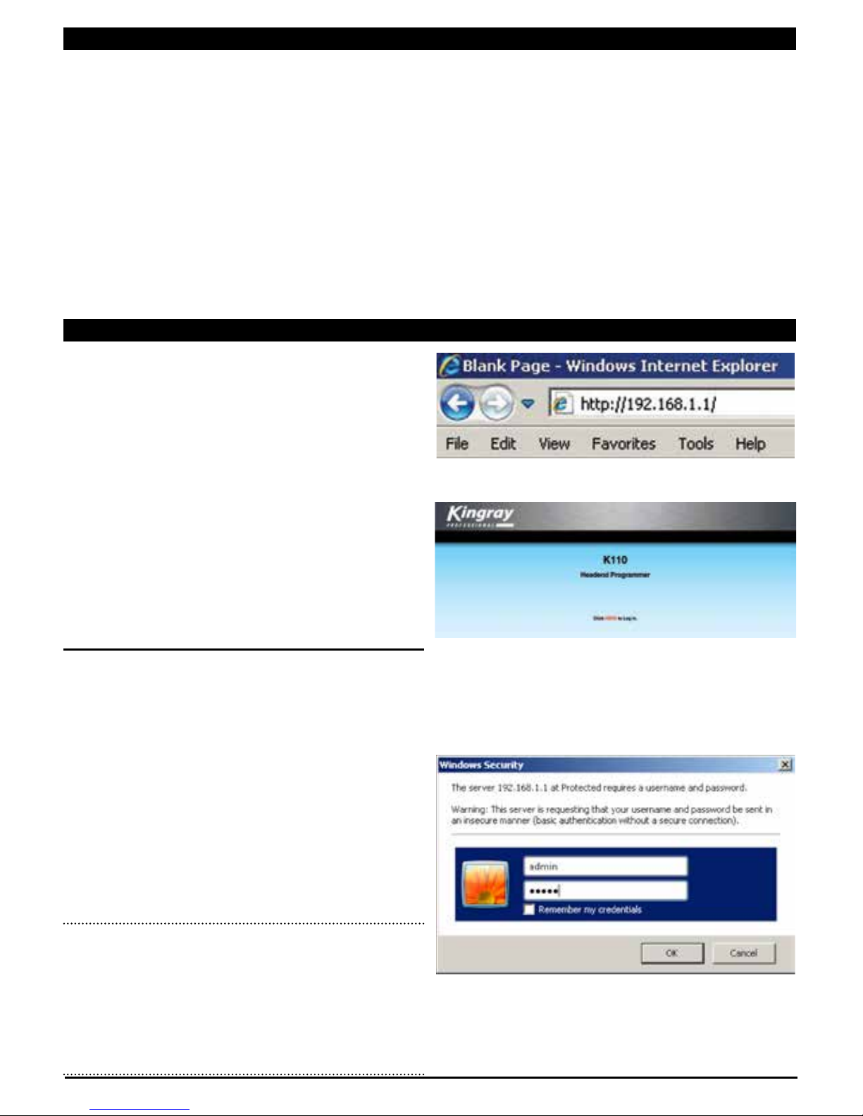
Once the rack has been mounted and all the modules installed
and connected, the next step is to locate each module so that
the software image mimicks the physical layout. After you have
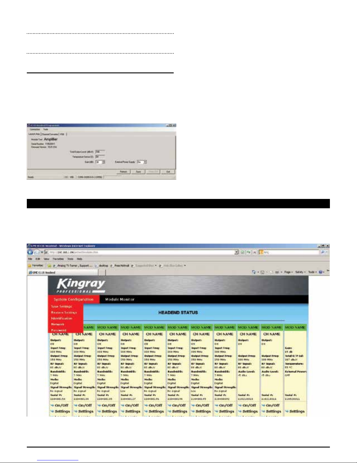
gained access to the system by using the password, you will see
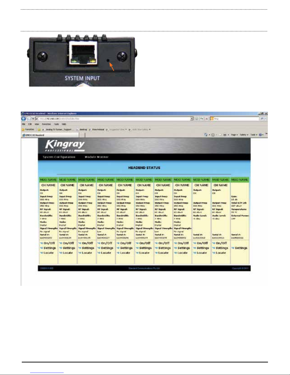
all modules displayed on your computer. Each module (KCC110/
KVM110) factory default location setting is -1, initially all the
modules in the software will be on the left hand side of the KLA-
110 (The KLA-110 will be on the far right hand side). .
In the headend software, click on
‘Locate’ at the bottom of a module. On
your computer display screen the green
bar at the top of the channel will flash.
Now physically look at the modules
when clicking ‘Locate’.
A Green LED on front of one of the modules will flash. Count
the module position as it is depicted in the drawing (Fig.1). Now
click on ‘Settings’ at the bottom of that module. This will open a
window where the settings can be changed. At this stage, change
the field that says ‘Module Position’ to the position it is phsyically.
NOTE: Module positions allowed are -5, -4, -3, -2, -1, or 1, 2, 3, 4,
5 depending on what side they are positioned on the KLA-110 launch
amplifier as shown in Fig.1.
Module Positions
-5 -4 -3 -2 -1 1 2 3 4 5
When you have changed the modules position, click on ‘write’
to save the information. Repeat these steps until all modules are
in their correct physical position. The system displayed on your
computer will replicate the number, position and type of modules
installed.
To change other settings such as channel name, input frequency,
output frequency, RF output level, bandwidth and mode, see
KCC110, or KVM110, and KLA110 Parameters.
2.1 KCC-110 PARAMETERS
In the KCC110 settings, you can change the
Module Name, Module Position, Channel Name,
Input frequency, Output Frequency, RF Output
Level, RF Output and Mode. In addition you can
monitor the output level.
To change these settings, click
on ‘settings’ at the bottom of the
appropriate module as displayed
on your computer screen. The
following window will appear.
The following parameters can be adjusted using the software.
Module Name: Text can be added to name the module.
Module Position: This is the actual module position in the
rack - position numbers that can be used
are -5, -4, -3, -2, -1, 1, 2, 3, 4, 5.
Channel Name: Text can be added to name the channel.
RF Output: You can switch the RF output ON or OFF
Input Frequency: Enter the frequency of the channel being
received - adjustable in 125 KHz steps
Output Frequency: Enter the frequency of the channel being
transmitted - adjustable in 125 KHz steps
RF Level: You can adjust the output level from 60 -
80dBuV
System Bandwidth: This is the bandwidth of the channel
being received - 7 or 8 MHz
Mode: This is used for the type of transmission
that is being processed or converted -
analogue or digital.
Once changes have been made, click ‘Write’ and the new settings
will be saved in memory.
FIG. 1

PAGE 5 PROGRAMMING MANUAL KLA-110
2.2 KVM-110 PARAMETERS
In the KVM-110 settings, you can change the
Module Name, Module Position, Channel Name,
Output Frequency, RF Level, RF Output, and
Input Volume.
To change these settings, click on ‘settings’
at the bottom of the appropriate module as
displayed on your computer screen.
The following parameters can be adjusted using the software.
Module Name: Text can be added to name the module.
Module Position: This is the actual module position in the
rack - position numbers that can be used
are -5, -4, -3, -2, -1, 1, 2, 3, 4, 5.
Channel Name: Text can be added to name the channel.
Output Frequency: Enter the frequency of the channel being
transmitted - adjustable in 125 KHz
steps.
RF Level: You can adjust the output level from 60 -
80 dBuV.
RF Output: You can switch the RF output ON or OFF.
Audio Input Level: Allows the user to adjust the input
volume level.
Once changes have been made, click ‘Write’ and the new settings
will be saved in memory.
2.3 KLA-110 PARAMETERS
In the KLA-110 settings, you can change the Module Name, the
Output Level via the gain, and switch the external power supply
on or off. Output Level and Temperature can also be monitored
from this page.
To change these settings, click on ‘settings’
at the bottom of the appropriate module as
displayed on your computer screen.
The following parameters can be adjusted using the software.
Module Name: Text can be added to name the module.
Gain: Adjustable between 14 to 45 dB, changing this
figure will change the output level. 45 dB gain
will give a maximum output level.
Output Level: True Broadband total RF output level of launch
amplifier.
Temperature: Operating temperature of power supply.
External Power: ON/OFF applies 18 volts @ 100mA to the
antenna input connection. This can be used to
power a masthead preamp.
NOTE: If no masthead or preamp is being used, ensure the external
power is set to ‘OFF’.
Once changes have been made, click ‘Write’ and the new settings
will be saved in memory.

PAGE 6 PROGRAMMING MANUAL KLA-110
3.0 PROGRAMMING THE SYSTEM
VIA USB CONNECTION
When only one module is being installed, use the USB software to
access and change the settings.
NOTE: The USB software was designed to be used with a PC. The
software will not work on Apple Computer Hardware.
1) Copy the software across to your C drive on the computer
being used to program the module.
2) Double click on the file TS0102.msi
You will see the following window/s appear. Follow the steps
through the installation process until finished.
3) Click ‘next’ to confirm the installation
4) Select the folder you wish to save the programme in and if
you want anybody else to have access to the software, then
click ‘next’.
5) Confirm the installation by clicking ‘next’.
6) A window will now appear indicating the installation process.

PAGE 7 PROGRAMMING MANUAL KLA-110
7) Once the installation programme is complete, click ‘close’.
8) Now you must install the device driver. Download or copy the
software across to C drive on the computer being used to
program the module. Double click on the directory CP210x.
9) Now double click and open up the directory Windows_2K_
XP_S2K3_Vista
10) Now double click on the file ‘CP210xVCPInstaller.exe’ to
install the software
11) The following window will now appear. Choose your location
and click ‘Install’.
12) Once the installation is complete, the following window
will appear.
3.1 OPERATING THE SOFTWARE
Now that the software has been installed, double click on the
shortcut on your desktop named TS0102.
NOTE: If you have problems communicating with any of the modules,
see Appendix B for further trouble shooting.

PAGE 8 PROGRAMMING MANUAL KLA-110
A new window will now appear asking you to select the product
you wish to program. From the target dropdown menu, choose
either KCC-110 Channel Converter, KVM-110 VSB Modulator, or
KLA-110 Launch Amplifier.
Before clicking ‘next’, make sure the device is connected and the
driver has been installed otherwise an error will occur
3.2 KCC-110 PARAMETERS
When choosing the Channel Converter, the following window will
appear.
The following parameters can be adjusted using the software.
Module Name Text can be added to name the
module.
Channel Name Text can be added to name the
channel.
System Mode Analogue or Digital signal to convert.
System Bandwidth Choose the channel bandwidth
applicable to your country e.g. 7
MHz for Australia, 8 MHz for other
countries.
RF-in (MHz) Enter in the frequency of the
incoming channel.
RF-out (MHz) Enter in the frequency of the
outgoing channel.
Output Level (dBuV) Enter the output level that you require
(between 60 - 80 dBuV).
Once changes have been made, click ‘Apply Changes’ and the
new settings will be applied to memory.
NOTE: Make sure that when making any changes, you ‘Apply
changes’ to save the new information
3.3 KVM-110 PARAMETERS
When choosing the VSB Modulator, the following window will
appear.
The following parameters can be adjusted using the software.
Module Name Text can be added to name the module.
Channel Name Text can be added to name the channel.
RF-out (MHz) Enter in the frequency of the
outgoing channel.
Output Level (dBuV) Enter the output level that you require
(between 60 - 80 dBuV).
Audio Volume Adjust audio level to increase or decrease
the volume.

PAGE 9 PROGRAMMING MANUAL KLA-110
Once changes have been made, click ‘Apply Settings’ and the
new settings will be applied to memory.
NOTE: Make sure that when making any changes, you ‘Apply
Settings’ to save the new information.
3.4 KLA-110 PARAMETERS
When choosing the Launch Amplifier, the following window will
appear.
The following parameters can be adjusted using the software.
Module Name Text can be added to name the module.
Gain Adjust gain of amplifier for desired
output level.
Temperature Sensor Temperature of power supply.
Output Level Output level set by Gain
(max 10 channels at 110 dBuV -60
dB IMR).
External Power: ON/OFF Allows 18 volts @ 100mA
to be feed out of the antenna input
connection. This allows for a masthead
or preamp to be used without using an
additional power supply.
Once changes have been made, click ‘Apply Changes’ and the
new settings will be applied to memory.
4.0 SYSTEM CONFIGURATION
• To check or change any parameters in the system configuration, hover the mouse over ‘system configuration’ and a drop down menu will appear.
Click on the desired setting that you wish to check or change.

PAGE 10 PROGRAMMING MANUAL KLA-110
4.1 SAVE SETTINGS
The system will allow you to save the parameters of the system.
This is particularly useful to clone a system when installing several
headends that are the same or just for record keeping.
To save the settings, in system configuration menu, click on ‘save
settings’ and the following window will appear. Click on ‘Save’.
The following window will now appear. Find a Directory you wish
to save the file to and type in the name you wish to call the file.
Then click ‘save’. The parameters will now be saved.
4.2 RESTORE SETTINGS
When cloning or uploading previously saved settings, in ‘system
configuration’ menu, click on ‘Restore settings’ and the following
window will appear. Click on ‘Browse’ to locate the saved file.
Click ‘Upload’. This will now upload the saved settings.
NOTE: When cloning a system, make sure the modules installed are
exactly the same configuration of the previous saved otherwise a
successful restore will not occur.
4.3 IDENTIFICATION
Identification allows the installer to put his or her details in the
system. This is ideal for information on who installed the system
or worked on the system last. This may also be useful for error
reporting.
To check or edit the identification settings, in system configuration
menu, click on ‘Identification’ and the following window
will appear.
To add or edit the text, click on ‘Edit’. A new window will appear.
Information can now be entered. Once complete, click ‘Write’. This
will save your information to memory.

PAGE 11 PROGRAMMING MANUAL KLA-110
4.4 NETWORK
This is important if any remote monitoring or controlling is
required when connecting to a network. You may find that the
default IP address (192.168.1.1) may conflict with another device,
such as a printer. To change the network settings, in system
configuration menu, click on ‘network’, then type in the new IP
Address, Network Mask, and Default Gateway and then click
‘Write’. This will now save the information in memory.
To make this a Dynamic IP address, click the box after ‘Use DHCP
to get IP Address’.
Remote monitoring/controlling can be done through a VPN. For
more information on setting up the system in an IT network,
contact the IT administrator who manages the customers network.
NOTE: Please make sure you write down any new zz address settings
so you are able to access the system again at a later stage.
4.5 PASSWORD
For increased security protection, the password can be changed
rather than using the default password ‘admin’. To change the
password, in system configuration menu, click on ‘Password’,
type in the NEW password and then retype the NEW password to
confirm. Click on ‘Update’. This will now save the new password
to memory.
4.6 RESETTING THE SYSTEM
The Kingray Professional series has built-in security features to
stop unauthorised people from accessing the system. To reset
the IP address and password back to default, use a blunt object
(such as a paperclip), to push into the small hole on the front of
the KLA-110. Hold this in whilst switching the system on for 3
seconds. You can now gain access to the system using the default
IP address and password.
Insert here
for 3 seconds
5.0 MODULE MONITOR
By clicking on module monitor you can update the current input
signal strength status and temperature of the system.

PAGE 12 PROGRAMMING MANUAL KLA-110
6.0 TROUBLE SHOOTING
NO COMMUNICATION VIA ETHERNET
Problem
I have connected the network cable directly to the KLA-
110 and computer, opened the web browser, entered
the default IP address (192.168.1.1), but there is still
no communication.
Solution
Check that you have set you computer with a static IP address
within the same range.
E.g. IP Address: 192.168.1.80
Subnet Mask: 255.255.255.0
Problem
I have connected the system as above but still no
connection. I noticed the communication LED’s do not
flash on the KLA-110 when plugging in the
ethernet lead.
Solution
If the computer you are using is old, (i.e. over 5 years old), you
may need to use a cross over cable.
NO COMMUNICATION VIA USB
Problem
I have loaded the driver, followed by the software, but
it doesn’t communicate with the module.
Solution
Check that your USB port in the computer is the same as what
the software is. Check you communication ports in Device
Manager and check in the USB software under the headings
‘Connection’ and ‘Settings’.
Problem
I ran the USB software but an error message came back
saying ‘Failed to read data from Channel Converter’.
Solution
Check that you have connected to a channel Converter module.
Instructions on how to change your IP address settings so you
can communicate with the Kingray Professional System. If your
computer is set up to obtain an IP address automatically, then
you will need to follow these instructions. Make sure that if
you do make changes to your IP settings, that you record your
current settings somewhere so you can change them back when
connecting back into your network.
USING WINDOWS XP
Go to START.
Click on SETTINGS.
Click on NETWORK CONNECTIONS.
APPENDIX A
CHANGING YOUR IP ADDRESS

PAGE 13 PROGRAMMING MANUAL KLA-110
Double click local area connection.
In the ‘General’ tab, look down the table of connections,
under the heading ‘THIS CONNECTION USES THE FOLLOWING
ITEMS:’ choose ‘INTERNET PROTOCOL (TCP/IP)’ then click on
‘PROPERTIES’.
A new window will appear.
NOTE: If your computer is set up to obtain an IP address
automatically then you won’t be able to connect directly to the
Kingray Professional Series. You must make sure you have a static IP
address set up as below to connect to the system.
Under the ‘General’ tab, enter in the following IP settings (other
IP addresses can be used providing it is in the same range as the
KLA110 eg 192.168.xx.xx).
Click OK.
Then click OK again.
Open up your browser and type in the default IP address
192.168.1.1 and press enter.
You should now have access to the Kingray Professional
Headend!

PAGE 14 PROGRAMMING MANUAL KLA-110
USING WINDOWS 7
Go to START, then click on CONTROL PANEL.
Click on NETWORK AND SHARING CENTER.
In the left hand column, click on CHANGE ADAPTER SETTINGS.
Double click the icon, LOCAL AREA CONNECTION.
Click on PROPERTIES.
Network and Sharing Center

PAGE 15 PROGRAMMING MANUAL KLA-110
Double click on INTERNET PROTOCOL VERSION 4 (TCP/IPv4).
A new window will appear
NOTE: If your computer is set up to obtain an IP address
automatically then you won’t be able to connect directly to the
Kingray Professional Series. You must make sure you have a static IP
address set up as below to connect to the system.
Under the ‘General’ tab, enter in the following IP settings (other
IP addresses can be used providing it is in the same range as the
KLA110 eg 192.168.xx.xx).
Click OK.
Then click OK again, then CLOSE.
Open up your browser and type in the default IP address
192.168.1.1 and press enter.
You should now have access to the Kingray Professional
Headend!

Drawing No: xx Part No: xx
A division of Standard Communications Pty Ltd. www.kingray.net.au
Head Office: PO Box 96, Winston Hills, NSW 2153. T: (02) 8867 6000 F: (02) 8867 6199 Enquiries/tech support: 1300 463 463
Sydney Melbourne Brisbane Adelaide Perth Auckland
(02) 8867 6000 (03) 9558 9999 (07) 3278 6444 (08) 8234 2633 (08) 9455 5744 (09) 274 0955
nswbrch@gme.net.au [email protected] qdbrch@gme.net.au sabrch@gme.net.au wabrch@gme.net.au [email protected]
Table of contents
Popular Power Supply manuals by other brands

Puls
Puls AS-Interface SLA4.100 installation manual

American Magnetics
American Magnetics 05100PS-430-601 Installation, operation and maintenance instructions

Thermal Dynamics
Thermal Dynamics Pak Master 75XL Plus operating manual

MAASLAND
MAASLAND KSG1C quick start guide

AJAX
AJAX 12-24V DC Conversion Board manual

Pulsar
Pulsar DSO-PRA manual

Eaton
Eaton AMPGARD Series Instructions for installation, use and maintenance

Phoenix Contact
Phoenix Contact EV-T2M3SO12-3P-P-SET manual

Proxxon
Proxxon NG 5/E manual

Southwire
Southwire Elite 1100 Series Operating and maintenance instructions

Kontron
Kontron 986LCD-M/mITX Information

Allen-Bradley
Allen-Bradley 1606-XLE480FP installation instructions