Kingsman Fireplaces IDV24 User manual

Installation Instructions
Gas Fireplace Insert Heater Listed Certified for USA. and Canada
Model Numbers:
IDV24 - Stock Numbers: IDV24N, IDV24NE, IDV24NE2, IDV24LP, IDV24LPE, IDV24LPE2
Minimum Fireplace Opening Required: 24-1/4”W x 18-1/2”H x 14”D
Are Certified to: CSA/ANSI Z21.88:19 • CSA 2.33:19 and CSA2.17-2017
VENTED GAS FIREPLACE HEATERS
⚠WARNING: The IDV24 Fireplace Insert was
designed for installation in a solid fuel fireplace
that has been installed in accordance with
national, provincial / state and local building
codes and is constructed of noncombustible
materials. Do not remove any refractory materials
from any masonry solid fuel fireplace.
The IDV24 Fireplace Insert was designed for
installation in a zero-clearance type listed solid fuel
burning factory-built fireplace. It may be necessary to
remove the damper plate, refractory liners, log grates,
glass door, and screen rails/mesh. Removal of the
smoke baffle is necessary in most cases.
A Division of R-Co. Inc.
2340 Logan Avenue
Winnipeg, Manitoba, Canada R2R 2V3
Ph: (204) 632-1962
Printed in Canada September 6, 2022
Part # 24IDV-MAN19
INSTALLER: Leave this manual with the
appliance.
CONSUMER: Retain this manual for
future reference.
This appliance may be installed in an aftermarket,
permanently located, manufactured home (USA
only) or mobile home, where not prohibited by
local codes.
This appliance is only for use with the type of
gas indicated on the rating plate. This appliance
is not convertible for use with other gases,
unless a certified kit is used.
CAPRI
VENTED GAS FIREPLACE HEATER:
NOT FOR USE WITH SOLID FUEL.

Important Information
INSTALLATIONS
•The following label (supplied with the gas fireplace insert) must be attached with rivets or screws to the inside of the
firebox of the fireplace into which it is installed:
•Cutting any sheet-metal parts of the fireplace, in which the gas fireplace insert is to be installed, is prohibited.
•If the factory-built fireplace has no gas access hole(s) provided, an access hole of 1.5 in (37.5 mm) or less may be drilled
through the lower sides or bottom of the firebox in a proper workmanship like manner. This access hole must be plugged
with non-combustible insulation after the gas supply line has been installed.
•The fireplace flue damper can be fully blocked open or removed for installation of the gas fireplace insert.
•Ensure that existing chimney cleanouts fit properly.
•refractory, glass doors, screen rails, screen mesh and
log grates can be removed from the fireplace before
installing the gas fireplace insert.
•Smoke shelves, shields and baffles may be removed if
attached by mechanical fasteners.
•Trim panels or surrounds must not seal ventilation
openings in the fireplace.
•The fireplace and fireplace chimney must be clean and
in good working order and constructed of non-
combustible materials. MAINTENANCE
•If for any reason the vent air intake system is disassembled, re-install and re-seal per the instructions provided for the
initial installation. See “Installation of Vent Pipe” section.
•It is recommended to annually inspect and clean the Burner System to prevent malfunction and / or sooting. This
operation should be performed by your dealer or a qualified technician. Refer to Burner System Maintenance section.
•Venting systems should be periodically examined by a qualified agency.
•Periodically remove the logs from the grate assembly and vacuum any loose particles from the grate and burner areas.
See Log Placement page to remove logs. Vacuum burner parts and replace logs.
-Glass Safety- All Units
IT IS THE RESPONSIBILITY OF THE HOME OWNER TO ENSURE THAT NO ONE TOUCHES A HOT APPLIANCE.
If the barrier becomes damaged, the barrier shall be replaced with the manufacturer’s barrier for this appliance.
Any safety screen, guard, or barrier removed for servicing the appliance, must be replaced prior to operating the
appliance.
•Children and adults should be alerted to the hazards of the high surface temperatures of this appliance and should stay
away to avoid burns or ignition of clothing.
•Do not clean when the glass is hot.
•Young children should be carefully supervised when they are in the same room as the appliance. Toddlers, young
children, and others may be susceptible to accidental contact burns.
•A physical barrier is recommended if there are at risk individuals in the house. To restrict access to a fireplace or stove,
install an adjustable safety gate to keep toddlers, young children and other at-risk individuals out of the room and away
from hot surfaces.
•Do not leave the fireplace remote control where it is accessible to children.
2

24IDV - Table of Contents
Important Information / Glass Safety…………………………………………………………………………………………
2
Table of Contents………………………………………………………………………………………………………………
3-4
Safety Screen Installation……………………………………………………………………………………………………..
5
Pre-installation Questions and Answers.....................................................................................................................
6
Operations and Maintenance Instructions..................................................................................................................
6
Warnings, Installations and Operations......................................................................................................................
7
Installation Requirements for the Commonwealth of Massachusetts.........................................................................
8
Carbon Monoxide (CO) Detector……………………………………………………………………………………………..
8
Mobile Home/Manufactured Housing Installation.......................................................................................................
9
IDV24 Fireplace Openings …………………………………………………………………………………………………...
10
IDV24 Fireplace Dimensions………………………………………………………………………………………………….
10
IDV24 Clean Views and Surround Options.................................................................................................................
11
I24SU4541 -Universal Surround- IDV24…………………………………………………………………………………….
12
IDV24 Mantel Heights.................................................................................................................................................
13
Wall Coverings, Side Walls, and Hearth Requirements.............................................................................................
14
Using Steel Studs and Concrete Board......................................................................................................................
14
Leveling Instructions………….....................................................................................................................................
15
IDV24 - Riser Kit Installation Instructions –Model No.: I34R40…………………………………………………………..
15
Surround Installations.................................................................................................................................................
16
Clean View Attachment..............................................................................................................................................
17
Media and Accessories
I33CS Mantel Clearance Shield Instructions………………………………………………………………………………..
18
IDV24RLT Brick Liner Panels.....................................................................................................................................
19
LOGF24DW Driftwood Log Setup……………………………………………………………………………………………
20
LOGF24OAK Oak Log Setup…………………………………………………………………………………………………
20
Crushed Glass and Media Options…………………………………………………………………………………………..
21
MQROCK2, MQROCK3……………………………………………………………………………………………………….
22
MQSTONE .................................................................................................................................................................
22
MQ EMBER Installation..............................................................................................................................................
23
RBCB1 Cannonballs…………………………………………………………………………………………………………...
23
Maintenance
Fan Removal / Installation..........................................................................................................................................
24
Halogen Lights- P2 Models Only……………………………………………………………………………………………..
25
Glass Door Information / Door Installation and Removal............................................................................................
26
Gas Section
Burner Removal / Burner System Removal / Installation...........................................................................................
27
Burner System Maintenance......................................................................................................................................
28
Conversion Kit Instructions –Part A..........................................................................................................................
29
Gas Conversion for SIT Top Convertible Pilot –Part B..............................................................................................
30
Gas Conversion for SIT Modulator –PART C............................................................................................................
31
Gas Line Installation / Gas Specifications…………………………………………………………………………………..
32
Millivolt System, Lighting, and Burner Control............................................................................................................
33
Lighting Instructions for Millivolt Valve with 7 Day Timer…………………………………………………………………..
34
IPI Lighting Instructions………………………………………………………………………………………………………..
35
Annual Inspection List for Determining Safe Operation of a Direct Vent Gas Fireplace……………………………….
36
Troubleshooting the Gas Control System...................................................................................................................
37
Proflame 1 IPI
Overview / Components.............................................................................................................................................
38
Junction Box Location................................................................................................................................................
39
IPI Proflame 1 -Remote Control Operation………………………………………………………………………………….
40
IPI Electronic Ignition Parts List –Standard System..................................................................................................
41
3

Configuration1 / Configuration 2.................................................................................................................................
42
Operating the Receiver Without Batteries for GT / EGT / GTM / EGTM Remote Controls........................................
43
Proflame 2 IPI
Proflame 2- Parts List.................................................................................................................................................
44
Proflame 2 IFC Module and Remote Control..............................................................................................................
45
Cold Climates –CPI Setting.......................................................................................................................................
46
Proflame 2 Remote Control Operation.......................................................................................................................
47-48
Proflame 2 Schematic.................................................................................................................................................
49
WMBH –Wall Mount Battery Holder –Proflame 1 and 2 IPI Models…………………………………………………….
50
Venting
IDV24 Venting Installation……………………………………………………………………………………………………..
51
IDV24 Vent Pipe Installation.......................................................................................................................................
52
Insulation of Chimney Cavity......................................................................................................................................
53
IDVVT32-KIT 2/3 Venting Adapter Kit……………………………………………………………………………………….
54
Parts List
IDV24 Parts List.........................................................................................................................................................
55-56
Limited Lifetime Warranty...........................................................................................................................................
57
4

Safety Screen Installation - IDV24 I24CSS
SAFETY SCREENS ARE SUPPLIED IN I24CV1BL Kits
To Install
Screen: Insert
Hooks on Safety
Screen into Slots
in Glass Door
Frame.
Procedure:
⚠WARNING: Wait until unit is COMPLETELY cool before touching glass or attempting
to install or remove Child Safety Screens.
GLASS DOOR IS
INSTALLED ON
FIREPLACE.
SHOWN REMOVED
FOR CLARITY ONLY
HOOK
SLOT
HOOK
SLOT
To remove Safety Screens
WAIT UNTIL FIREPLACE IS COMPLETELY COOL.
Lift up on Safety Screen Frame and disengage Hooks in Safety Screen from Slots in Glass Door Frame.
1: Engage Lower Hooks in Slots.
2: Raise Screen. Ensure that
Lower Hooks remain engaged.
Top Hook is directly above Slot.
3: Lower Screen. Watch both sides to
ensure that Top Hooks engage properly.
5

Pre-installation Questions and Answers
About curing of the paint
Your stove or fireplace has been painted with the highest quality silicone stove paint. This paint dries quickly in 15-20
minutes when first applied at the factory. However, due to the high temperature silicone components, the paint will cure
when heat is applied to the appliance as it is first used. The following information applies to the curing process to get the
paint fully hard and durable.
Fire the appliance four successive times for 10 minutes each firing and a 5 minute cool down between each. Be aware
during log and firebox paint curing that a white deposit may be developing on the inside of the glass doors. It is important
to remove this white deposit from the glass doors using a fireplace glass cleaner.
Babies, small children, pregnant women and pets should leave the area during the cure phase.
Ventilate well, open doors and windows.
Do not touch during curing.
Why does my fireplace or stove give off odor?
It is normal for your fireplace to give off some odor at first. This is due to the curing of the paint, adhesives, silicones and
any undetected oil from the manufacturing process as well as the finishing materials used with the installations (e.g.
marble, tile and the adhesives used to adhere this product to the walls can react with heat and cause odors).
It is recommended that you burn your gas fireplace or stove for a minimum of four hours at a time with the fan off (if a fan
is present) after the curing of the paint has been completed. These odors can last upward to 40 hours of burn time; keep
burning at a minimum of four hours per use until odors dissipate.
Noise coming from the fireplace?
Noise is caused by the expansion and contraction of metal as the appliance heats up and cools down. This is normal and
is similar to the sounds produced by a furnace or heating duct. This noise does not affect the operation or longevity of
your fireplace.
It is also normal for the fan to make some noise when it comes on. This noise can be reduced somewhat by turning down
the speed of the fan with the variable speed control. Be aware, however, that this will reduce the volume of heated air
circulated into the room by the fan.
Note to the Installer:
Be sure appliance is working properly and its operation (including remote control operation, if included) is fully explained
to and understood by the customer.
Operations and Maintenance Instructions
For safe installation and operation note the following:
Be sure to read and understand all the instructions in this manual before operation of appliance.
Ensure all wiring is correct and properly enclosed to prevent possible shock.
Check for gas leaks.
Make sure the glass door is properly installed before operation. Never operate the appliance with the glass door
removed.
Make sure venting and termination cap are installed and unobstructed.
If brick or porcelain liners are used, ensure they are installed.
Verify that the pilot can be seen when lighting the appliance. If not, the log or rock placement is incorrect.
If the unit is turned off, you must wait a minimum of 60 seconds before re-lighting it.
Venting systems should be periodically examined by a qualified agency.
The flow of combustion and ventilation air must not be obstructed.
The Burner/Log Assembly has been engineered and permanently adjusted for proper flame control.
Periodically remove the logs from the grate assembly and vacuum any loose particles from the grate and burner
areas. See Log Placement page to remove logs. Vacuum burner parts and replace logs.
Never use your gas fireplace as a cooking device.
Label all wires prior to disconnection when servicing controls. Wiring errors can cause improper and dangerous
operation. Verify proper operation after servicing.
Areas in and around the Chase Vent Openings should be cleaned annually.
6

Warnings, Installations and Operations - Installation Regulations
This gas appliance must be installed by a qualified installer in accordance with local building codes, or in the absence of local codes, with the
current CAN/CSA-B149.1 or .2 Installation Code (in Canada) or the current National Fuel Gas Code Z223.1- NFPA 54 when installed in the
United States.
This appliance, when installed, must be electrically connected and grounded in accordance with local codes, or in the absence of local codes,
with the current CSA C22.1 Canadian Electrical Code or with the National Electrical Code; ANSI/NFPA 70 when installed in the United States.
WARNING
FOR SAFE INSTALLATION AND OPERATION OF YOUR GAS FIREPLACE PLEASE NOTE THE FOLLOWING:
1. Do not clean when the glass is hot.
2. Do not use abrasive cleaners.
3. Using a substitute glass will void all product
warranties.
4. For safe operation, glass doors must be closed.
5. When purging the gas line, the glass front must be
removed.
6. Do not strike or abuse glass. Take care to avoid
breakage.
7. Do not alter gas orifice.
8. No substitute materials may be used other than
factory supplied components.
9. This appliance gives off high temperatures and should
be located out of heavy traffic areas and away from
furniture and draperies.
10. Children and adults should be alerted to the hazards
of the high surface temperatures of this appliance and
should stay away to avoid burns or ignition of clothing.
11. Young children should be carefully supervised when
they are in the same room as the appliance. Toddlers,
young children and others may be susceptible to
accidental contact burns. A physical barrier is
recommended if there are at risk individuals in the
house. To restrict access to a fireplace or stove, install
an adjustable safety gate to keep toddlers, young
children and other at risk individuals out of the room
and away from hot surfaces.
12. Under no circumstances should any solid fuels (wood,
paper) be used in this appliance.
13. Under no circumstances should this appliance be
modified. Any parts that have to be removed for
servicing should be replaced prior to operating this
appliance.
14. Any safety screen, guard, or barrier removed for
servicing an appliance must be replaced prior to
operating the appliance.
15. Installation and repair should be done by a qualified
service person. The appliance should be inspected
before use and at least annually by a professional
service person. More frequent cleaning may be
required due to excessive lint from carpeting, bedding
material, et cetera. It is imperative that control
compartments, burners and circulating air
passageways of the appliance be kept clean. Make
sure that the gas valve and pilot light are turned off
before you attempt to clean this unit.
16. Clothing or other flammable material should not be
placed on or near the appliance. This appliance
should not be used as a drying rack for clothing nor
should Christmas stockings or decorations be hung
from it.
17. Do not use this heater if any part has been under
water. Immediately call a qualified service technician
to inspect the heater and to replace any part of the
control system and any gas control which has been
under water.
18. Do not operate appliance unless completely installed
as per installation instructions.
19. Failure to position the parts in accordance with these
diagrams or failure to use only parts specifically
approved with this appliance may result in property
damage or personal injury.
20. WARNING: Do not operate appliance with the
glass front removed, cracked or broken.
Replacement of the glass should be done by a
licensed or qualified service person.
21. The appliance area must be kept clear and free from
combustible materials, gasoline, and other flammable
vapors and liquids.
22. The front of the fireplace gives off high temperatures
that could ignite combustible material which is kept
close to the front of the unit.
23. Ensure that power to the Fireplace is turned off before
servicing.
24. Do not operate this Fireplace without the glass front or
with a broken glass.
25. Improper installation, adjustment, alteration, service or
maintenance can cause injury or property damage.
Refer to the owner’s information manual provided with
this appliance. For assistance or additional information
consult a qualified installer, service agency, or the gas
supplier.
26. Operation of this appliance when not connected to a
properly installed and maintained venting system or
tampering with the blocked vent shutoff system can
result in carbon monoxide (CO) poisoning and
possible death.
27. This appliance is equipped with a three-prong
(grounding) plug for your protection against shock
hazard and should be plugged directly into a properly
grounded three-prong receptacle. Do not cut or
remove the grounding prong from this plug.
28. NOT INTENDED FOR USE AS A PRIMARY HEAT
SOURCE. This appliance is tested and approved as
either supplemental room heat or as a decorative
appliance. It should not be factored as primary heat in
residential heating calculations.
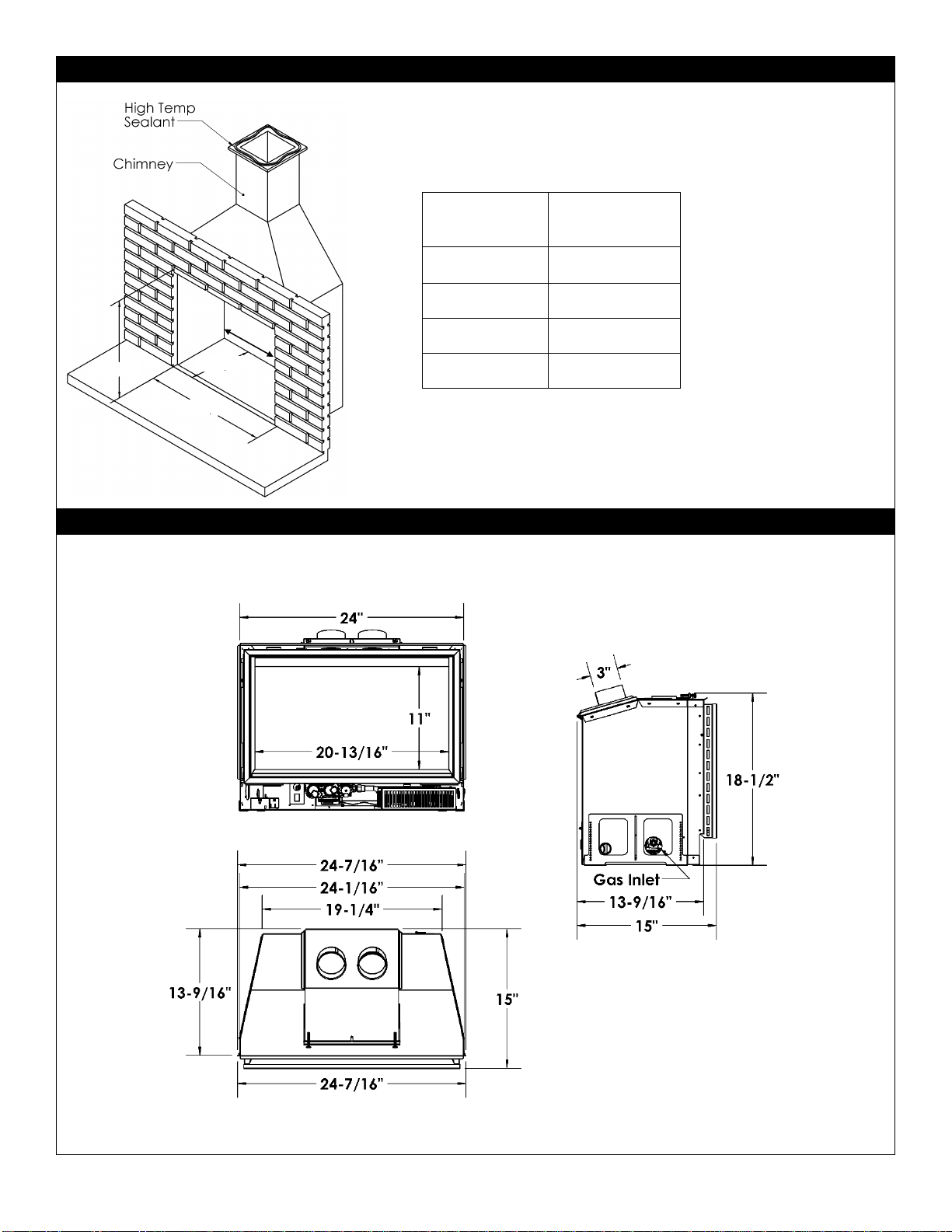
29. This appliance must not be connected to a chimney
flue serving a separate solid-fuel burning appliance.
7

Installation Requirements for the Commonwealth of Massachusetts
In the Commonwealth of Massachusetts, the installer or service agent shall be a plumber or gas fitter licensed by the
Commonwealth.
When installed in the Commonwealth of Massachusetts or where applicable codes; the unit shall be installed with a CO
detector per the requirements listed below.
1. For direct-vent appliances, mechanical-vent heating appliances or domestic hot water equipment, where the bottom of
the vent terminal and the air intake is installed below four feet above grade the following requirements must be
satisfied:
A. If there is not one already present, on each floor level where there are bedroom(s), a carbon monoxide
detector and alarm shall be placed in the living area outside the bedroom(s). The carbon monoxide detector
shall comply with NFPA 720.
B. A carbon monoxide detector shall be located in the room that houses the appliance or equipment and shall:
Be powered by the same electrical circuit as the appliance or equipment such that only one service switch
services both the appliance and the carbon monoxide detector;
Have battery back-up power;
Meet ANSI./UL 2034 Standards and comply with NFPA 720; and
Have been approved and listed by a Nationally Recognized Testing Laboratory as recognized under 527
CMR.
C. A Product-approved vent terminal must be used, and if applicable, a Product-approved air intake must be
used. Installation shall be in strict compliance with the manufacturer’s instructions. A copy of the installation
instructions shall remain with the appliance or equipment at the completion of the installation.
D. A metal or plastic identification plate shall be mounted at the exterior of the building, four feet directly above
the location of vent terminal. The plate shall be of sufficient size to be easily read from a distance of eight feet
away, and read “Gas Vent Directly Below”.
2. For direct-vent appliances, mechanical-vent heating appliances or domestic hot water equipment where the bottom of
the vent terminal and the air intake is installed above four feet above grade the following requirements must be
satisfied:
A. If there is not one already present, on each floor level where there are bedroom(s), a carbon monoxide
detector and alarm shall be placed in the living area outside the bedroom(s). The carbon monoxide detector
shall comply with NFPA 720.
B. A carbon monoxide detector shall:
Be located in the room that houses the appliance or equipment;
Be either hard-wired or battery powered or both; and
Shall comply with NFPA 720.
A Product-approved vent terminal must be used, and if applicable, a Product-approved air intake must be used.
Installation shall be in strict compliance with the manufacturer instructions. A copy of the installation instructions shall
remain with the appliance or equipment at the completion of the installation.
For the state of Massachusetts a T-handle gas shut-off valve must be used on a gas appliance. This T-handle gas shut-
off valve must be listed and approved by the state of Massachusetts. This is in reference to the state of Massachusetts
state code CMR238.
Carbon Monoxide (CO) Detector
NOTE: It is recommended that a Carbon Monoxide (CO) Detector be installed in or near bedrooms and on all levels of
your home. Place a detector about 15ft [4.5m] outside the room that houses your gas appliance.
Certified for installation in a bedroom or bed/sitting room. In Canada must be installed with listed millivolt thermostat.
In USA see local codes.
8

Mobile Home/Manufactured Housing Installation
This Direct Vent System Appliance must be installed in accordance with the manufacturer’s installation instructions and
the Manufactured Home Construction and Safety Standard Title 24 CFR, Part 3280, or the current Standard for Fire
Safety Criteria for Manufactured Home Installation, Sites, and Communities ANSI/NFPA 501A, and with CAN/CSA Z240
MH Mobile Home Standard in Canada.
THIS APPLIANCE MAY BE INSTALLED IN MANUFACTURED (MOBILE) HOMES AFTER FIRST SALE.
Please follow the current ANSI/NFPA 70 National Electrical Code in the USA and CAN/CSA C22.1 Canadian National
Electrical Code in Canada.
An appliance must be grounded to the steel chassis of the home with 8ga. copper wire using a serrated or star washer to
penetrate paint or protective coating to insure grounding.
Use carriage bolt at the attachment point (see diagram above) to secure the appliance to the floor.
Bedroom approved.
For required venting components see venting installation in appropriate section of this manual.
⚠Warning:
Do not compromise the structural integrity of the manufactured home wall, floor or ceiling, during installation
of appliance or venting.
Ground to steel chassis of mobile home.
Use existing hole or remove existing screw
to mount ground wire to screw.
Use 8 gauge copper wire and serrated
washer and bolt.
9

IDV24 Fireplace Openings
REQUIRED
DIMENSION
AFront Width
24-1/4”
BHeight
18-1/2”
CDepth
14”
DBack Width
19-1/4”
IDV24 Fireplace Dimensions
“A”
“B”
“C”
“D”
LEFT SIDE
FRONT
TOP
10

IDV24 - Clean View and Surround Options
I24CV1BL
I24CV1BL with
I24S3827 Surround
I24CV1BL with
I24S3827 Surround,
I34R40 Riser,
I33CS Mantel Clearance Shield
I24CV1BL with
I24SPF3829 Picture Frame Surround
I24CV1BL with
I24SU4541 Universal Surround
11

I24SU4541 -Universal Surround- IDV24
For use with I24CV1BL.
This Surround can be custom cut and bent.
NOTE: If you wish to make the bottom of the surround flush
with the fireplace bottom, cut surround at dotted line.
The Surround Ledge can be removed by drilling out the three
rivets.
Surround Ledge
12

IDV24 Mantel Heights
IDV24 Combustible Mantel Heights
Dimension
Mantel
Depth
I24CV1 Only
or with
Surround
I24CV1 with
Surround and I33CS
Mantel Shield
A
0”
31-1/8”
31-1/8”
B
2”
33-1/8”
33-1/8”
C
4”
35-1/8”
35-1/8”
D
6”
37-1/8”
37-1/8”
E
8”
39-1/8”
39-1/8”
F
10”
41-1/8”
41-1/8”
⚠WARNING: Combustible objects must not be placed on a non-
combustible mantel unless the non-combustible mantel meets the
minimum height and width requirements for a combustible mantel.
A
B
C
D
E
F
13

IDV24 –Wall Coverings, Side Walls and Hearth Requirements
Refer to Mantel Heights Chart for detailed information.
Using Steel Studs and Concrete Board
Brick facing may be removed and replaced with non-combustible materials such as steel studs and concrete board. The
opening between the firebox and non-combustive materials must be sealed so as the heat cannot run between the face of
the wood fireplace and the re-facing materials.
Insert must be pulled out so the appliance is flush with the finishing materials and the clean view kit is proud of the finished
non-combustible enclosure (wood burning fireplace).
1/2” MIN
Clearance
required to
remove Clean
View
Combustible Mantel Line
SIDE WALL CLEARANCE TO
COMBUSTIBLES
TOP VIEW
Floor beneath
appliance must be
non-combustible.
Use steel studs
Use concrete board on front and
around steel stud enclosure for insert
Must be sealed to avoid heat
entering old enclosure
Existing zero clearance wood
burning / masonry fireplace
Must be sealed to avoid heat
entering old enclosure
12”NON-
COMBUSTIBLE AREA
ABOVE FIREPLACE
14

IDV24 - Leveling Instructions
When installing insert it may be necessary to support back of unit. There are two leveling legs at the back sides of the
appliance. Measure the height of the space to be leveled. Remove screws and set leveling legs to proper height.
Replace screws.
IDV24 - Riser Kit Installation Instructions –Model No.: I34R40
⚠WARNING: Failure to position the parts in accordance with these diagrams or failure to use only parts
specifically approved with this appliance may result in property damage or personal injury.
Right Side
View
Measure
Height
Leveling Leg
Leveling Legs
Locate slots at bottom front of
unit. Place riser assembly
under front of insert and
fasten to base with supplied
screws.
Measure the height
required and set the
Riser Supports.
Slots in
Fireplace
Bottom
Riser
Support
Riser
Support
Note: For a minimum opening width of 24-1/4”:
Riser must be trimmed 9/16” on both sides as shown below.
15

IDV24 –Surround Installation
IDV24 Surrounds: I24S3827, I24SPF3829, 124SU4541
All surrounds attach to the back of the Clean View.
Surround Attachment:
PARTS LIST:
-Surround
- [Qty 9] #6 Black Screws
STEP 1:
Place Surround against back
of Clean View
STEP 2:
Attach Surround with [9]
screws supplied with
surround.
BACK
VIEW
Surround
Clean View with attached Surround can now be installed onto Fireplace.
Clean View
I24S3827
I24SPF3829
124SU4541
16

IDV24 Clean View Attachment
Parts List:
-I24CV1BL Clean View
-Safety Screen
NOTE: Vent adapter and venting must be connected to the unit before Clean Views
and Surrounds are attached. Refer to Installation of Vent Pipe section of this manual for
venting information.
SECTION 1: Optional Surrounds are fastened to the Clean View.
If a surround is to be used, install onto the CV Kit before it is mounted.
SECTION 2: Clean View Mount Slots are located beside the Safety Screen Frame on the Fireplace. Insert the [4]
Clean View Mount Hooks into the Clean View Mount Slots and lower the Clean View into place.
SECTION 3: Millivolt Systems - Install ON/OFF Switch into right side of Clean View. See below.
ON / OFF Switch
Mounting
Hooks
Mounting
Hooks
Clean View
Optional
Surround
Clean View
Mounting Slot
Clean View
Mounting Slot
Clean View
Mounting Slot
Clean View
Mounting Slot
Safety Screen
Frame
Safety Screen
Frame
Clean View
Optional
Surround
Clean
View
Clean View
Mounting Slots
NOTE: Clean
View Hooks
have 2 slots 1/4”
apart.
Optional ON / OFF
Switch location for
Millivolt units (above
Piezo igniter)
17

I33CS Mantel Clearance Shield Instructions Option
Place I33CS upside down on a protected surface. Loosen screws.
Center surround onto I33CS. Tighten screws to hold surround in place.
Surround is now ready to install onto Clean View.
Contents of Kit: [1] Mantel Clearance Shield c/w Screws
18

IDV24RLT Brick Liner Installation Option
Installation:
1. Remove Brick Clips from sides of firebox.
2. Install the Back Panel.
3. Carefully slide and tilt Side Panels into place.
4. Reinstall Brick Clips into upper sides of firebox.
Parts List
-1 Back Panel
-1 Right Side Panel
-1Left Side Panel
Brick Clip
Left Side Panel
Right Side Panel
Back Panel
19

IDV24 LOGF24DW Driftwood and LOGF24OAK Oak Log Setup Option
Place Log 1 against the back wall of the firebox.
Place Log 2 in the center of the firebox directly over the
burner.
Place Log 3 along the right-side wall of the firebox.
Place Log 4 along the left side wall of the firebox.
Place Log 5 at the front of the firebox, just to the left of
center.
Place Log 6 across Log 1 and Log 2 on the left side.
Place Log 7 across Log 1 and Log 2 on the right side.
Place Embers and Insulation Wool directly onto Burner. Place Lava Rock around sides and front of firebox bottom.
*Lava Rock
⚠WARNING: Failure to position the parts in accordance with these diagrams or failure to use only parts
specifically approved with this appliance may result in property damage or personal injury.
*NOTE: THESE ITEMS
ARE SUPPLIED WITH
THE FIREPLACE:
*Insulation Wool
*Embers
1
2
3
4
5
7
6
20
This manual suits for next models
6
Table of contents
Popular Heater manuals by other brands

VOLTOMAT HEATING
VOLTOMAT HEATING FH-102994.2 instruction manual

Master
Master B 1,8 ECA owner's manual

TTL Torluftschleier
TTL Torluftschleier TTL-TWISTO Assembly and operating instructions

Sawo
Sawo Cirrus Rock CRR2-30NB manual

Whirlpool
Whirlpool HT015 user manual

cecotec
cecotec Ready Warm 9790 Force instruction manual