Kingspan BF BIODISC Instruction sheet

GL0016P
INSTALLATION GUIDELINES
FOR BIODISC®UNITS
BF, BG, NF & NG
Contact Numbers:
UK:
Service Tel: +44 (0) 845 355 0555
Service Fax: +44 (0) 1264 325245
Ireland:
Service Tel: +44 (0) 28 302 54077
Service Fax: +44 (0) 28 302 60046
BioDisc is the registered trademark of Kingspan Environmental.
510031P BF Single Phase Panel Wiring Diagram
The following wiring diagrams are provided with in the control panel housing.
If additional copies are required contact Kingspan.
510030P BF 3 Phase Control Panel Wiring Diagram
510003P BF 3 Phase Alarm Control Panel Wiring Diagram
510017P BF Single Phase Alarm Control Panel Wiring Diagram
510012P BG, NF & NG Single Phase Panel Wiring Diagram
510013P BG, NF, & NG Single Phase Alarm Control Panel (Option L/M)
510006P BG, NF & NG 3 Phase Control Panel Wiring Diagram
510007P BG, NF & NG 3 Phase Alarm Control Panel
510018P Independent Loss of Rotation Alarm
Issue Description Date
02 CC841 May 2010
Enclosed Documents

GL0016P-02 Installation Guidelines for BioDisc®Units BF, BG, NF & NG
2
HEALTH AND SAFETY
These warnings are provided in the interest of safety. You must read them carefully before installing or using the
equipment.
It is important that this document is retained with the equipment for future reference. Should the equipment be transferred
to a new owner, always ensure that all relevant documents are supplied in order that the new owner can be acquainted with
the functioning of the equipment and the relevant warnings.
Installation should only be carried out by a suitably experienced contractor, following the Guide-Lines supplied with the
equipment.
We recommend the use of a dust mask and gloves when cutting GRP components.
Electrical work should be carried out by a qualified electrician.
Sewage and sewage effluent can carry micro-organisms harmful to human health. Any person carrying out maintenance on
the equipment should wear suitable protective clothing, including gloves. Good hygiene practice should also be observed.
Covers must be kept locked.
Observe all hazard labels and take appropriate action to avoid exposure to the risks indicated.
The correct ongoing maintenance is essential for the proper operation of the equipment. Kingspan offer a range of
maintenance contracts, details on request.
Should you wish to inspect the operation of the equipment, please observe all necessary precautions, including those listed
below, which apply to maintenance procedures.
BioDisc units contain rotating machinery and associated drive chains or belts.
Ensure that you are familiar with the safe working areas and accesses.
Ensure that the working area is adequately lit.
The power supply to the equipment must be isolated at the control panel(s) before lifting the covers. Where a specific
maintenance procedure requires the equipment to be running with the covers off, all care must be taken to avoid contact
with moving parts and electrical components or conductors. Drive guards must be replaced and secured if removed during
maintenance.
Once power has been isolated, the control panel must be kept locked shut to avoid accidental re-connection whilst work or
inspection is being carried out.
Use only the designated access walkways. Do not walk on the cover or deep well safety mesh(es). Desludge port covers,
where fitted, must be replaced if removed.
Take care to maintain correct posture, particularly when lifting. Use appropriate lifting equipment when necessary. Keep
proper footing and balance at all times. Avoid any sharp edges.
Desludging should be carried out by a contractor holding the relevant permits to transport and dispose of sewage sludge.
The contractor must refer to the desludge instructions in the Operating Manual, a copy of which is fastened under the
covers.

GL0016P-02 Installation Guidelines for BioDisc®Units BF, BG, NF & NG
3

GL0016P-02 Installation Guidelines for BioDisc®Units BF, BG, NF & NG
4
CONTENTS
Page
Health & Safety ............................................................................................................................................2
Declaration of Conformity ..............................................................................................................................3
1.0 Introduction ............................................................................................................................................4
2.0 Handling & Storage................................................................................................................................4
3.0 Site Planning..........................................................................................................................................4
4.0 Installation - General..............................................................................................................................5
Concrete Specification...........................................................................................................................6
5.0 BioDisc Installation ................................................................................................................................6
6.0 Control Panel Installation.......................................................................................................................8
7.0 Ancillary Equipment ...............................................................................................................................9
8.0 Start Up ..................................................................................................................................................9
1.0 Introduction
These Guidelines represent Best Practice for the installation of these Kingspan BioDisc Units. Many years
of specialist experience has led to the successful installation of thousands of BioDisc units. It must be noted,
however, that these Guidelines are necessarily of a general nature. It is the responsibility of others to verify
that they are appropriate for the specific ground conditions and in-service loads of each installation.
Similarly, any information or advice given by employees or agents of Kingspan regarding the design of an
installation must be verified by a qualified specialist (e.g. Civil engineering consultant).
2.0 Handling & Storage
2.1. Care must be taken to ensure that the unit is not damaged during delivery and handling on site.
2.2. Whenever Kingspan BioDisc unit are stored or moved on site, ensure that the storage location is free
of rock, debris and any sharp objects which may damage the unit. The BioDisc must be placed on
ground which is flat and level to evenly support the base of the unit.
2.3. Lifting equipment should be selected by taking into account the unit weight, length and the distance of
lift required on site.
2.4. The design requirements of Kingspan products will frequently mean that the centre of gravity of the
unit is “offset”. Care must therefore be taken to ensure that the unit is stable when lifting. Rainwater
may collect also inside units, particularly if they have been stored on site prior to installation, adding
weight and increasing instability. Check units before lifting and pump out any excess water.
2.5. When lifting units, use webbing slings of a suitable specification. Do not use chains in contact with the
product.
2.6. A suitable spreader bar should be used to ensure that the unit is stable and that loads are evenly
distributed during lifting. When lifting BioDisc units the spreader bar length should be equal to the
width of the BioDisc to avoid compression damage to the covers or sides of the unit.
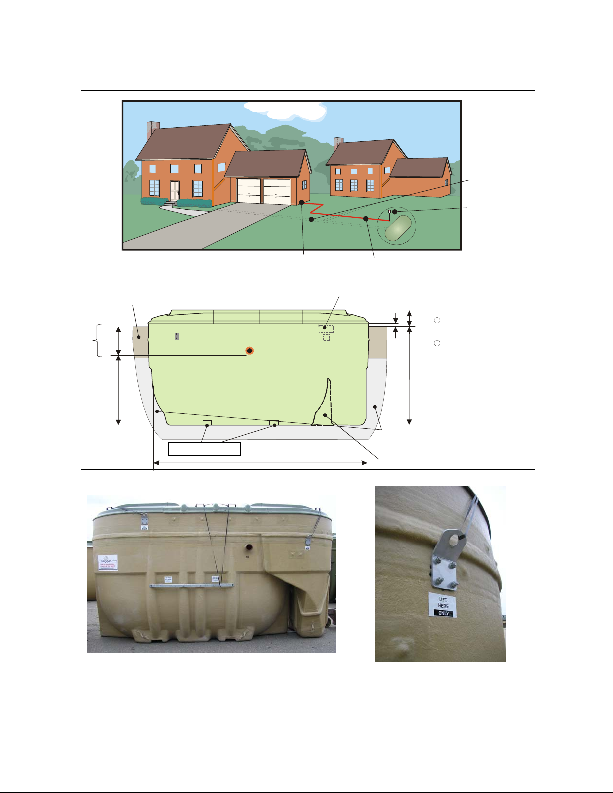
2.7. BF and NF BioDisc units should be lifted by webbing straps passed through the two channels in the
base of the unit. Do not use the U-bolts on the BioDisc case for lifting.
2.8. BG and NG BioDisc have an off-set centre of gravity and should not be lifted by the base channels as
this would risk tipping over the unit. Lift using 4 the new metal lifting brackets as indicated by labels on
the unit. The old slinging points are still in the bottom of the mould, they are not to be used under any
circumstances.
2.9. Kingspan Environmental accepts no responsibility for the selection of lifting equipment.
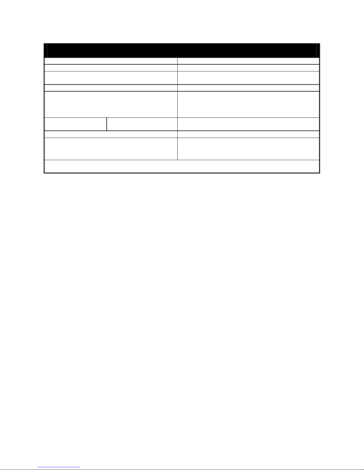
3.0 Site Planning
The following points should be considered before installation of the equipment:
3.1. The discharge must have the consent of the relevant Environmental Regulator.
3.2. The installation should have Planning and Building Control approval.
3.3. Ground conditions and water table level should be assessed. If the water table will be above the base
of the unit at any time of the year, adequate concrete backfill must be provided to avoid flotation. In
poorly draining ground, consideration should also be given to the likelihood of flotation due to surface
water collecting in the backfill. It should be borne in mind that the inlet drain trench will act as a land
drain, directing surface water to the backfill around the unit.

GL0016P-02 Installation Guidelines for BioDisc®Units BF, BG, NF & NG
5
3.4. If discharge is to a soakaway, a porosity test should be carried out in accordance with BS 6297 to
assist in assessing sub-soil drainage and designing the sub-surface irrigation system.
3.5. The BioDisc system must be installed at a level which will allow connection to the incoming drain and
a free discharge at the system outlet.
3.6. The unit should be installed so that the bottom lip of the cover is 65mm or more above local ground
level. If the unit has to be recessed, measures must be taken to ensure that it cannot be flooded by
surface water run-off.
3.7. There must be at least 1 metre of clear, level ground all around the unit to allow for routine servicing,
plus adequate space to allow complete removal of the covers.
3.8. The unit should be installed as far as possible from any habitable building. Many Local Authorities will
insist on a minimum distance of 15 metres.
3.9. Adequate access must be provided for routine de-sludging and maintenance, including crane access.
Vehicles should not be permitted within a distance equal to the depth of the unit, unless suitable
structural protection is provided to the installation.
3.10. BioDisc covers are not suitable for walking on. Where necessary the BioDisc should be fenced off or
otherwise protected. Maintenance access must be maintained as above.
3.11. An adequate electrical supply must be provided, complying with current electrical regulations. The
electrical details in Section 6.2.6. will enable selection of suitable cable and current overload
protection, taking into account the distance from the power source to the control panel and any other
relevant factors. In most cases steel wire armoured (S.W.A).cable, minimum 1.5sq mm will be
suitable, but this is a minimum recommendation and selection is the responsibility of the installing
electrician. Although not obligatory for an installation of this type, RCD protection is suggested as an
extra precaution.
3.12. Pump stations or any other associated equipment should have a separate power supply.
3.13. Proximity to a mains water hosepipe connection point is recommended, for maintenance purposes.
Such a supply should be connected in accordance with water bylaws and regulations. Never leave a
hose connected and immersed in sewage.
3.14. Installation should only be carried out by suitably qualified and experienced contractors in accordance
with the Health and Safety at Work Act. Electrical work should be carried out by a qualified electrician,
working to the latest edition of IEE.
4.0 Installation - General
4.1. When units are installed in unstable ground conditions where movement of the surrounding material
and/or unit may occur, the connecting pipework should be designed to minimise the risk of damage
from differential movement of the unit(s) and/or surrounding material.
4.2. In situations where the excavation will not maintain a vertical wall, it will be necessary to support side
walls of the excavation (eg. with suitable trench sheets and bracing systems) to maintain a vertical wall
from the bottom to the top of the excavation. DO NOT completely remove the shoring system until after
the backfilling is complete, but before the concrete fully hardens.
4.3. In areas where the water table is above the bottom of the excavation and/or the excavation is liable to
flood, the excavation should be de-watered, using suitable pumping equipment, until the installation is
complete. In such conditions it may be advisable to line the excavation with polythene sheeting, to
prevent cement being washed out of the concrete surround/base.
4.4. During installation care must be taken to ensure that the body of any unit is uniformly supported so
that point loads through the unit are avoided.
4.5. A water supply must be available on site to enable the unit to be ballasted during backfilling.
4.6. Concrete Specification is a general specification. It is not a site specific installation design.

GL0016P-02 Installation Guidelines for BioDisc®Units BF, BG, NF & NG
6
GENERAL CONCRETE SPECIFICATION
IN ACCORDANCE WITH BS EN 206-1 ( BS 8500-1)
TYPE OF MIX (DC) DESIGN
PERMITTED TYPE OF CEMENT BS 12 (OPC): BS 12 (RHPC): BS 4027 (SRPC)
PERMITTED TYPE OF AGGREGATE
(coarse & fine)
BS 882
NOMINAL MAXIMUM SIZE OF AGGREGATE 20 mm
GRADES: C25 /30
C25 /30
C16 /20
REINFORCED & ABOVE GROUND WITH HOLDING
DOWN BOLTS
REINFORCED (EG. FOR HIGH WATER TABLE)
UNREINFORCED (NORMAL CONDITIONS)
MINIMUM CEMENT
CONTENT
C30
C20
270 - 280 Kg/M3
220 - 230 Kg/M3
SLUMP CLASS S1 (25mm)
RATE OF SAMPLING READY MIX CONCRETE SHOULD BE SUPPLIED
COMPLETE WITH APPROPRIATE DELIVERY
TICKET IN ACCORDANCE WITH BS EN 12350-1
NOTE: STANDARD MIXES SHOULD NOT BE USED WHERE SULPHATES
OR OTHER AGGRESSIVE CHEMICALS EXIST IN GROUND WATER
5.0 BioDisc Installation
5.1 Remove the package tied to the outside of the unit. This contains a cover key.
5.2 Excavate a hole of sufficient length and width to accommodate the unit and a minimum of 150mm
concrete surround and to a depth which allows for the burial depth of the unit plus a minimum 150mm
thick concrete base.
5.3 Construct a suitable concrete base slab, a minimum of 150 mm thick, appropriate to site conditions.
In wet or unstable ground conditions it may be necessary to lay a hard-core sub-base (see notes 3.3 &
4.3). Ensure that the slab is flat and level. Allow the slab to set sufficiently to support the installed load,
but not so much as to prevent subsequent backfill bonding fully to the base.
5.4 Ensure that the slab is free of any stones or other material which could damage the unit. Lower the
unit onto the slab using suitable webbing slings and lifting equipment.
5.5 Remove the covers by undoing the locks and folding the end covers back over the inner covers before
lifting them off.
5.6 Remove the Control Panel and Owners Pack from the walkway inside the unit.
5.7 Check that the inlet and outlet orientation is correct and that the unit is level. It is essential that the unit
is installed in a level plane to avoid undue stress on the bearings.
The rotor shaft must be level end to end, to within ±3mm, measured at the bearing caps or directly on
the shaft.
The unit must also be level to within ±5mm from side to side, measured at the GRP walkway on either
side of the rotor.
If necessary, lift the unit off the base and apply further concrete as needed to level up.
Note : The top flange of the BioDisc should not be used for levelling as manufacturing tolerances may
result in it not being parallel with the rotor shaft.
5.8 It is essential that levels given above are checked regularly throughout the installation process. Should
the unit become out of level, immediate remedial action is advised, to maintain the unit within the
levels stated in section 5.7.
5.9 Pour no more than 1 metre depth of water into both primary (inlet) chambers and the final (outlet)
chamber ensuring that there is never more than 250mm difference in water level between any of the
sections.

GL0016P-02 Installation Guidelines for BioDisc®Units BF, BG, NF & NG
7
5.10 BG and NG BioDisc have an off-set centre of gravity and should not be lifted by the base channels as
this would risk tipping over the unit. The old slinging points are still in the bottom of the mould, they are
not to be used under any circumstances. Lift using the 4 new metal lifting brackets as indicated by
labels on the unit.
Power Supply
from house
240V 1ph (3ph optional)
( RCD p r ot e cte d - Cust om e r su pp l y)
St e e l W i r e Ar m o ur e d
Cable supply
to control panel -
Customer Supply
Inlet Pipe
Control Pa nel
G.L.
600mm
Inlet Invert
Add 100mm For
Outlet Invert
Concrete backfill minimum
150mm thick
b u t t o su i t sp e ci f i c
site conditions.
Concrete, Pea Shingle or
other suita ble free flowing
mater ia l followed by
topsoil or finish to
suit site requirements
2420mm
BG/ NG Length 5235mm (Width 2450)
BF/ NF Length 4345mm (Width 2450)
Internal Volumes of Units as an
aid to Ca lculate Materia ls
Approximate Weights (Empty):
Base to Working Water Level
(Outlet Invert)
Base to Ground Level
1
2
BF 12.7m BG 14.92m
3 3
Not less
tha n 65mm
Inlet
1820mm
405mm
BF/ NF 1350 Kgs
BG/ NG 1700 Kgs
Backfill void (BG & NG only)
with concrete
BF 16.3m BG 19.4m
3 3
Sling points BF/ NF BG/ NG
Drive Motor
Slin
g
p
oints BF/NF

GL0016P-02 Installation Guidelines for BioDisc®Units BF, BG, NF & NG
8
5.11 Place concrete backfill to approximately 500mm depth around the unit ensuring good compaction to
avoid voids. Do not use vibrating pokers.
5.12 Continue backfilling with concrete up to the level of the outlet. Keep the concrete at an even level all
round the unit, compacting in layers. As backfilling progresses keep the ballast water level inside the
unit 250-500mm above the concrete backfill level, but do not attempt to fill the unit with water above
the outlet level.
5.13 BG and NG only: Ensure that concrete is fed into the area between the two casings to eliminate voids
as far as possible and assist in anchoring the unit.
5.14 Connect the inlet and outlet pipework when safe access can be gained. Short lengths of “rocker” pipe
with flexible joints should be used adjacent to the unit to allow for any minor differential movement.
5.15 Check the cables attached to the control panel and drill the corresponding number of 40mm holes in
the BioDisc case, 100mm below ground level and adjacent to one end of the interior walkway. If an
Independent Remote Alarm is to be fitted this will also require a 40mm hole.
5.16 Erect the Control Panel as described in Section 6.0.
5.17 Continue backfilling to ground level with concrete, pea shingle (3-18mm), or similar non-cohesive,
non-compressible free-flowing granular material. Do not use sand. The finished surface should be
65mm minimum lower than the lip of the cover.
5.18 Important : Read section 8.2 regarding delayed electrical installation.
6.0 Control Panel Installation
6.2. General Installation
6.1.1. The control panel should be positioned adjacent to the unit, so that:
a) It does not interfere with cover removal.
b) It is convenient for the incoming power supply.
c) It cannot be reached by someone standing in or on the BioDisc unit.
d) It is close enough to enable the electrical connections to be made in the BioDisc.
This usually indicates a panel position about 1.5 metres distance from the BioDisc, adjacent to the
inlet or outlet.
6.1.2. Set the panel leg(s) in a concrete base, minimum 250mm thick and prop the panel to prevent
movement until the concrete has set. Allow 350mm minimum clearance from ground level to the
bottom of the panel.
6.1.3. Control panels are supplied with pre-fitted steel wire armoured (s.w.a.) cable(s), complete with
grommets and glands. Lay the cable(s) in a 500mm deep trench and bed them on a layer of sand or
similar soft material.
6.1.4. Insert the cables through the hole(s) in the casing of their respective unit(s), using the grommets
supplied. Leave the cable(s) temporarily secured above water level pending electrical installation.
6.1.5. Cover the cable(s) with a layer of sand or similar soft material and warning tape. Backfill the cable
trench with graded spoil, free of large stones or any other material which might damage the cable(s).
6.1.6. The Control Panel key is in the protective bag at the end of the motor/gearbox cable.
6.2. Electrical Installation
6.2.1. Depending on type, the control panel is supplied with between one and three pre-fitted armoured
cables.
a) Every Control Panel has a motor/gearbox cable.
b) Control Panels for NF, NG and BG units have an additional Sludge Return Pump cable.
c) Alarm Control Panels have an extra cable for the Loss of Rotation sensor.
Each cable is fitted with a gland for connection to the terminal box or junction box and a grommet for
entry into the BioDisc case.

GL0016P-02 Installation Guidelines for BioDisc®Units BF, BG, NF & NG
9
6.2.2. Connect the cable(s) to the appropriate electrical junction(s) in the BioDisc, fitting the glands
supplied. The cables can be identified by their numbered end connectors which correspond to
connection points in the BioDisc. The end numbers on the motor/gearbox cable correspond with the
numbered terminals in the motor/gearbox terminal box.
Connection Point Connector Type End Numbers
Motor/Gearbox
Three Phase : 1, 2, 3, Earth
Terminal Box Single Phase : 1, 3, Earth
Sludge Return
Pump
Junction Box fixed
inside BioDisc Case Pin L1, N1, Earth
Loss of Rotation
Alarm
Junction Box fixed to
Motor Support Beam Pin
6, 7, Earth
6.2.3. Ensure that cables inside the BioDisc are securely tied to the structure, clear of the drive
arrangement and do not present a trip hazard.
6.2.4. Units may be supplied with an optional Independent Remote Alarm (used in conjunction with a
standard Control Panel). This is supplied with a fixing kit. Install in accordance with the installation
instructions provided. Please note that the Remote Alarm Unit should not be installed more than 100
metres from the BioDisc and that the interconnecting cable (customer supply) should be laid in a
separate trench to prevent electrical interference.
6.2.5. Connect the incoming power supply to the control panel, using suitable cable and current overload
protection. (See section 3.11). Ensure that the panel is securely closed.
Full Load Current (Amps)
BF BG NF NG
240 volt single phase 1.3 1.55 1.3 1.55
415 volt three phase 0.69 0.67 0.69 0.67
Sludge return pump 240 volt single phase only N/A 2.4 2.4 2.4
7.0 Ancillary Equipment
Ancillary items should be installed in accordance with the Installation Guide supplied e.g.
Crude Sewage Pump Station, Effluent Pump Station, Effluent Sample Chamber, Grease Trap.
8.0 Start Up
8.1. Refer to the Owners Handbook for details of the Start Up Procedure.
8.2. Once the unit has been installed it should be left filled with water. Please switch on the motor,
following the procedure in the Owners Handbook and leave the unit running, even if there is no
sewage being fed into the plant. If the unit has been installed with no operational power supply, then
remove the motor/gearbox unit, and drive chain/belt and store them in a dry or heated environment
until such time as the unit is ready for permanent operation.
BioDisc is the registered trademark of Kingspan.
Motor/Gearbox Pin
Motor

GL0016P-02 Installation Guidelines for BioDisc®Units BF, BG, NF & NG
10
This manual suits for next models
3
Table of contents
Popular Water Filtration System manuals by other brands

Brassmaster
Brassmaster PLUS MEGAbite Installation & operation manual

Baldor
Baldor Dodge SLEEVOIL instruction manual

Watts
Watts PWSYS-FIL-ICE3 Installation and operation manual

Aquafine
Aquafine RBE Series Installation, maintenance and operation manual

Sharp
Sharp E-Filter user manual

Viega
Viega 4970 Instructions for use

Cuno
Cuno CFS6000 series Installation and operating instructions

Insignia
Insignia NS-HAF-CIN-1 Quick setup guide

Osmio
Osmio Ecopure Eco-8 installation instructions

Clean Water Systems
Clean Water Systems 7500 Series Installation & start?up guide

GCTek
GCTek AquaBead instructions

Donaldson Torit
Donaldson Torit 684LP Installation, operation and maintenance manual