manuals.online logo
Brands
  1. Home
  2. •
  3. Brands
  4. •
  5. Kinman
  6. •
  7. Accessories For Musical Instruments
  8. •
  9. Kinman TK4 User manual

Kinman TK4 User manual

Page 1 of 5
Install Guide for the ‘Kinman’ TK4 NoSoldering Harness Rev 4 for Telecasters
with specially made pots, guaranteed to maximize sonic performance.
Rev-5 13
th
March 2006. © Chris Kinman
CAUTION: Avoid using Lead solder on Lead Free products bearing this symbol
NOTE-1: Read this completely first before beginning the project.
NOTE-2: The pickup selector switch has 4 positions.
1. Bridge
2. Br + Neck in parallel
3. Neck
4. Bridge + Neck in series (fat sound with increased output for crunch)
NOTE-3: If you have a problem after this install please refer to the Harness Diagnostics sheet on this Webpage
to diagnose your problem. Contact Us if you have no success.
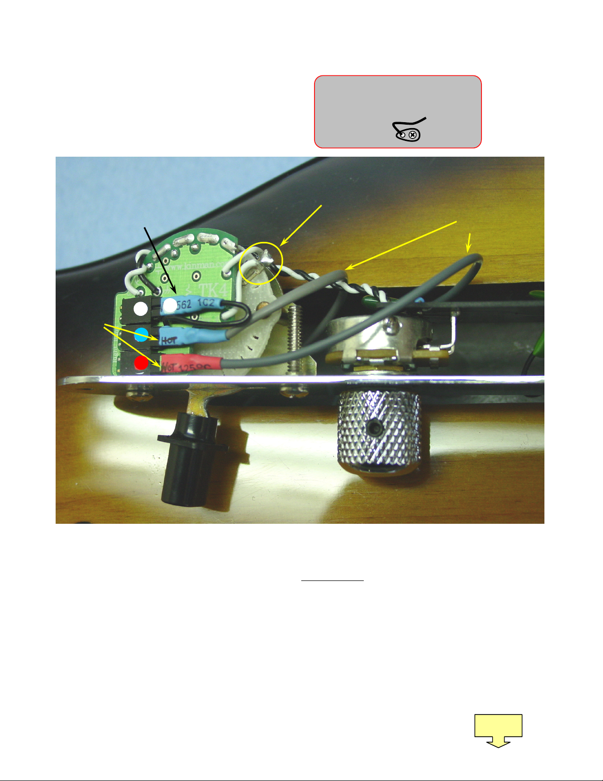
NOTE-4: The Tone control is set to High Definition so treble cut is minimal. Reset the slide switch in photo 2 to
get normal treble cut.
Tools needed:
oSmallish/Medium X head screwdriver to remove and replace the pickguard and Control Plate mounting
screws.
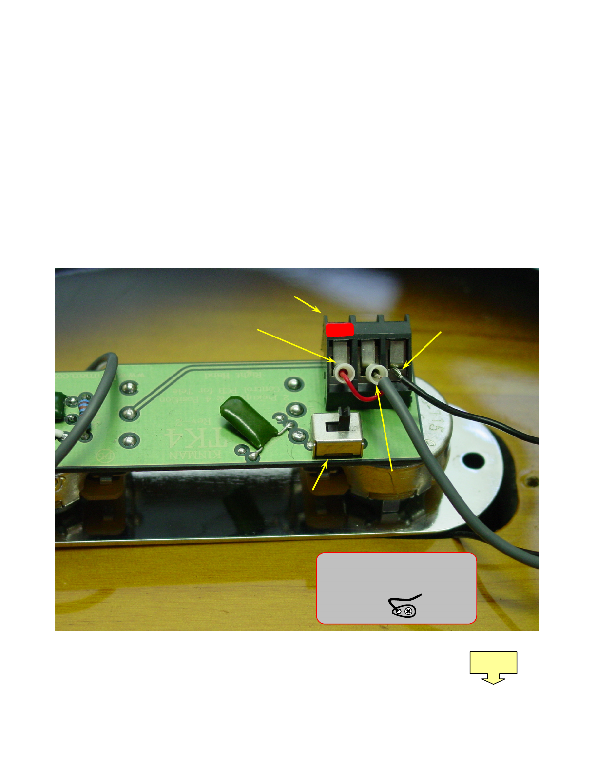
oSmall blade screwdriver to tighten the terminal block connections.
oRazor blade or other small sharp blade to cut plastic insulation on Black ground wire. If you have cloth
covered wires you don’t need to cut it, just push it back to expose bare wire. (see #2)
oUSA Models: ½” (or 13mm) tube spanner (or nut driver) to tighten the jack socket.
Non USA models: In addition to above you will need an 11mm tube spanner (or other nut driver) to
remove the original jack socket.
1) Remove both the strings and the pickguard.
2) Cut or break the ground wire(s) (coming from the bridge -and/or- from the central ground point, as the case
may be) away from the casing of the volume pot by working the wire(s) around and around in a circle at
the solder point until it breaks. Then cut and strip or push the insulation back about 1/4” (6mm) so it or
they are ready to insert into one of the ports of the screw terminal block mounted on the PCB.
3) WARNING: DO NOT disturb or loosen any screw and associated solder tabs like this that are
attached to the floor or wall of any cavity. These provide a ‘ground’ for the conductive coating (Shielding)
that is applied to the cavities and doing so will render the Shielding ineffective causing buzzing noise level
to be excessive when you let go of the strings. Simply putting them back as they were before removal will
not reconnect the ground.
4) Remove the Control plate and cut or break the pickup connections and output jack connections.
5) Remove the pickups and bridge from the guitar.
6) Remove the output jack socket by unscrewing the outside nut and withdrawing the socket into the control
cavity.
NOTE: As much as possible try to keep the original wiring harness in tact for future use.
The guitar should now have no remaining connections to the original pickup or controls and you now should be
ready for the Kinman install.
7) Unpack and remove the replacement pickups, Control plate and output jack socket from the Red plastic
shipping plate.
8) Mount the neck pickup to the body or pickguard as the case may be, using the Red silicone rubber tubes
as springs around the screws.
omounted from the pickguard: Use the Kinman 4-40 UNC (Tele) & 6-32 UNC (Strat) mounting screws.
omounting direct to wood: Use only the Red silicon rubber tubes over the original long wood screws to
mount the pickup. The tubes may have to be shortened so cut with sharp blade or scissors. Do not
pack foam under the pickup as this will stress and bend the pickup and it may become
damaged.
Page 2
Pb
Pb-Free
Page 2 of 5
9) Mount the bridge pickup into the bridge plate using the three 6-32 UNC screws supplied and the Red
silicon rubber spring tubes over those screws.
NOTE: The bridge pickup has a layer of copper over the baseplate which provides a grounding path via
the mounting screws to the bridge and strings. The screws should always protrude at least slightly through
the baseplate in order to contact the copper plate. No other bridge ground wire is necessary, but will not
harm anything if it already exists and is re-used, although the screw terminal block has limited access.
CAUTION: Failure to get a good connection between the 3 screws and the copper plate will result in
dreadful noise, especially when you touch the strings.
10) Poke the pickup cables through the connecting tunnels into the control cavity. Hint: If you have a Warmoth
Tele body you will see they drill the wiring connecting tunnel for the neck pickup on an excessively steep
angle causing the tunnel to exit below the control cavity floor. To provide clearance for the harness
connector it will be necessary to remove a small amount of wood as shown in the diagram below. This is
preferable to cutting the harness cable.
11) Mount the output jack socket to the side mounting plate (recessed or flush). On most Teles it is preferable
not to remove the mounting plate from the guitar, the socket can be inserted via the control cavity into the
socket cavity. However with certain Teles it may be necessary to remove the jack mounting plate to gain
access to the jack socket. On these types of guitars there may be a small diameter tunnel connecting the
socket cavity to the control cavity. Thread the cable through the tunnel into the control cavity. The two
plugs on the cable should be piggy backed, one inside the back of the other, as depicted in the photo (1)
below. This arrangement makes it easier to feed through the connecting tunnel.
oNOTE: The Star washer should not be fitted on the outside underneath the nut, but only on the inside
between the mounting plate and the socket.
oMake sure the socket is tightened in the position where the *hot* leaf-spring terminal is centred on the
recessed jack holder, otherwise it might contact the wall of the cavity and cause a partial short via the
wood or shielding resulting is BAD sound. Also this makes the plug difficult to insert.
oOn some copy guitars it may be necessary to enlarge the cavity to avoid the short mentioned above.
Photo 1
Page 3
Connecting tunnel
Neck
pickup
cavity
Control
cavity
Diagram 1: Applies Only to Warmoth Tele bodies
Remove small section of wood from floor of cavity to provide
clearance for harness connector to exit the tunnel.
Page 3 of 5
12) Undo the 3 screws to open the terminal ports and insert the two Plugs and ground wire(s) into their
respective screw terminals as shown in photo (3) on page 4. The Red wire is plugged into the (left)
terminal. The Shield is plugged into the middle terminal and the black ground wire/s (from the shielding
and/or bridge –and/or- the central ground point, as the case may be) into the remaining terminal (right).
Tighten the screws firmly but not too tightly.
NOTE: I do not advocate Star grounding, in fact it can cause headaches. Bear in mind all shielding and
ground wires should be somehow connected (either directly or indirectly) to the right hand port of the
Connector-block. This includes the control cavity shielding and output cavity shielding (if present). Since it
is not recommended to insert more than 2 wires into the connector-block ports all these elements can be
connected together at another point and a single wire leading from that point to the right hand port of the
connector-block. CAUTION: Failure to ground any shielding will result in excessive unwanted noise.
Ground wire/s
from central
ground point or
shielding.
Red wire from
output socket.
cable Shield
Slide switch
for selecting Hi-Definition
or Normal tone caps.
3 port connector block
Photo 2
DO NOT TAMPER
with these
types of tabs fixed to wood as
the shielding will be permanently
damaged.
Page 4
Page 4 of 5
13) Plug the pickups into their respective sockets on the plate mounted on the side of the switch. Make sure
the hot pin goes to the correct side of the socket. It has HOT handwritten on the side of the plug that is the
Hot pin and the socket is also labelled. CAUTION: DO NOT bend the sockets away from the circuit board.
14) You will notice the neck pickup has 2 plugs. One is for grounding only and has a single black wire attached
to the cable. This plus into the socket marked 'Neck ground'
15) Bringing the control plate to the cavity, arrange the pickup cables to avoid getting squeezed between the
walls of the cavity and the hardware parts. The cables should be arranged as shown in Photo 4 (next
page) The control plate should sit snug to the body, poorly arranged cables can prevent this.
16) Very rarely the angled switch may not fit entirely within the control cavity per Diagram 2 below. Should this
be the case simply tighten the 2 control plate mounting screws firmly with the intention of embedding the
two extreme tips of the corners of the switch frame into the wood. If they won’t push into the wood
completely then position a piece of wood like a short length of broom handle or dowel onto the control
plate directly above the extreme corners of the switch frame: tap the top of the piece of wood with a small
hammer or mallet. Take care that this action does not damage either the guitar or the control plate: tap
only sufficiently to seat the control plate flush onto the wood.
Page 5
Pic
kup
cables
Photo 3
Ho
t side of
plugs go
closest to
the control
plate.
This terminal must
NOT
be bent over.
Ground plug for
neck pickup with
single Black wire
DO NOT TAMPER
with these
types of tabs fixed to wood as the
shielding will be permanently
damaged.
Page 5 of 5
17) Otherwise fit the screws to the control plate and the pickguard taking care not to cross thread the screws in
the wood.
18) Proceed to restring and adjust the pickup heights.….. Please visit www.kinman.com >Tone Workshop
>Tone for detailed info on how to get the best out of your pickups and guitar. There is a wealth of
information in this section of my Website that will fascinate and delight you for many hours.
End
Press the tips of the switch frame
into the wood if they don’t align
within the cavity.
Diagram 2:
Position of the small dowel on which
to lightly hammer as instructed in 15)
Shield
Photo 4
Arrange the cables to
lie in the gap between
the switch and the
Volume pot while
replacing the control
plate.
This
swi
tch
terminal
must NOT be bent over.

Other Kinman Accessories For Musical Instruments manuals

Kinman Tele User manual

Kinman

Kinman Tele User manual

Kinman Hx Instruction Manual

Kinman

Kinman Hx Instruction Manual

Kinman P-90 Mounting Plate Instruction Manual

Kinman

Kinman P-90 Mounting Plate Instruction Manual

Kinman K9 NoSoldering Harness User manual

Kinman

Kinman K9 NoSoldering Harness User manual

Kinman Goodbye K9 User manual

Kinman

Kinman Goodbye K9 User manual

Kinman Jazzmaster Hx User manual

Kinman

Kinman Jazzmaster Hx User manual

Popular Accessories For Musical Instruments manuals by other brands

Schaller Signum Bridge USER GUIDE & PRODUCT INFORMATION

Schaller

Schaller Signum Bridge USER GUIDE & PRODUCT INFORMATION

Fodera Dual Action Truss Rod Adjusting Manual

Fodera

Fodera Dual Action Truss Rod Adjusting Manual

Konig & Meyer 12170 manual

Konig & Meyer

Konig & Meyer 12170 manual

ORANGE Bax Bangeetar user manual

ORANGE

ORANGE Bax Bangeetar user manual

TerraTec AXON AX 100 MKII manual

TerraTec

TerraTec AXON AX 100 MKII manual

EES M3 Oktaver operating instructions

EES

EES M3 Oktaver operating instructions

EMG SA/SA/85 Set Installation information

EMG

EMG SA/SA/85 Set Installation information

Raw Vintage USA RV-TE installation guide

Raw Vintage

Raw Vintage USA RV-TE installation guide

Wenger Maestro Acoustical Ceiling installation instructions

Wenger

Wenger Maestro Acoustical Ceiling installation instructions

aion HELIOS manual

aion

aion HELIOS manual

Fishman SONITONE installation guide

Fishman

Fishman SONITONE installation guide

L.R. Baggs M1 Installation manual & users guide

L.R. Baggs

L.R. Baggs M1 Installation manual & users guide

Fishman FLUENCE SB1 installation guide

Fishman

Fishman FLUENCE SB1 installation guide

EMG SPC manual

EMG

EMG SPC manual

EMG EMG-91 ARCHTOP Installation information

EMG

EMG EMG-91 ARCHTOP Installation information

Dusty Strings TriStander Direction for Installation and Use

Dusty Strings

Dusty Strings TriStander Direction for Installation and Use

Suzuki MRT- 01 manual

Suzuki

Suzuki MRT- 01 manual

EMG X Series Installation information

EMG

EMG X Series Installation information

manuals.online logo
manuals.online logoBrands
  • About & Mission
  • Contact us
  • Privacy Policy
  • Terms and Conditions

Copyright 2025 Manuals.Online. All Rights Reserved.