KirbEbike NC-81F User manual

Electric Bike Display
User’s Manual
NC-81F
www.kirbebike.com

TABLE OF CONTENTS
1.
PRODUCT NAME AND MODEL NUMBER ................................................................................................................................. 1
2.
SPECIFICATION........................................................................................................................................................................ 1
3.
APPEARANCE AND SIZE........................................................................................................................................................... 1
4.
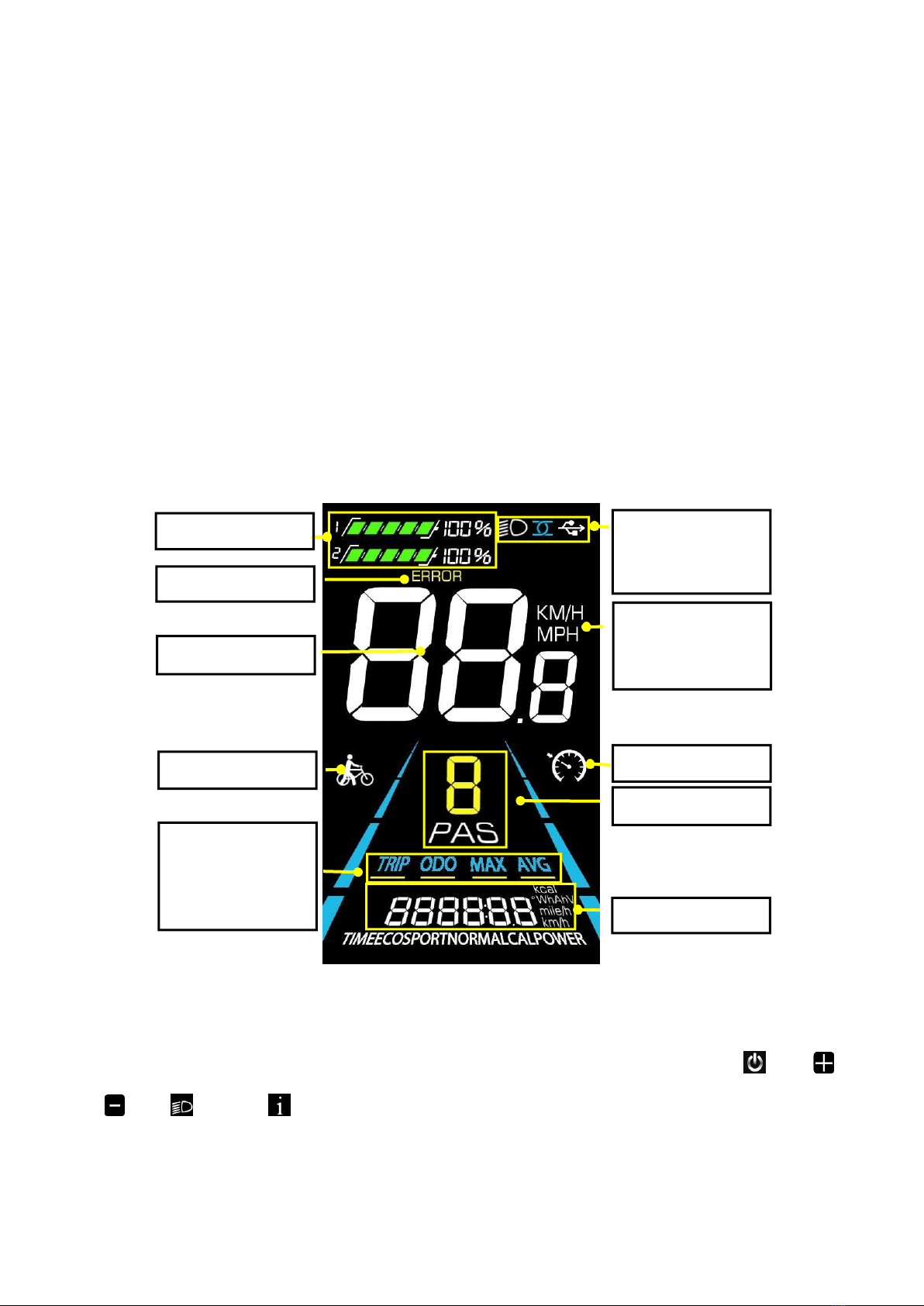
FUNCTION OVERVIEW AND FUNCTIONAL AREAS.................................................................................................................... 3
4.1
FUNCTIONAL OVERVIEW...........................................................................................................................................................................................................3
4.2
FUNCTIONAL AREAS...................................................................................................................................................................................................................3
4.3
BUTTON DEFINITIONS.................................................................................................................................................................................................................3
5.
ROUTINE OPERATION ............................................................................................................................................................. 4
5.1
POWER ON/OFF.............................................................................................................................................................................................................................4
5.2
DISPLAY INTERFACE SWITCHING...........................................................................................................................................................................................4
5.3
WALK BOOST MODE AND CRUISE ENABLE SETTING.....................................................................................................................................................................5
5.4
TURNING ON/OFF LIGHTS.........................................................................................................................................................................................................6
5.5
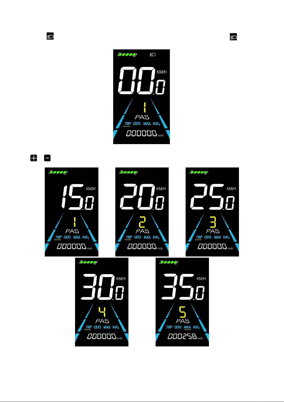
PAS LEVEL SELECTION...................................................................................................................................................................................................................6
5.6
BATTERY LEVEL DISPLAY................................................................................................................................................................................................................7
5.7
ERROR CODE DISPLAY..............................................................................................................................................................................................................7
5.8
BRAKE PROMPT DISPLAY....................................................................................................................................................................................................................8
6.
PERSONALIZED PARAMETER SETTINGS................................................................................................................................... 8
6.1
BACKLIGHT LUMINANCE SETTING.......................................................................................................................................................................................9
6.2
METRIC AND IMPERIAL SETTING..............................................................................................................................................................................................9
6.3
RATED VOLTAGE SETTING.....................................................................................................................................................................................................10
6.4
AUTO SLEEP TIME SETTING.....................................................................................................................................................................................................10
6.5
PAS LEVEL SETTING................................................................................................................................................................................................................11
6.6
WHEEL DIAMETER SETTING ..................................................................................................................................................................................................11
6.7
NUMBER OF SPEED SENSOR MAGNETS SETTING.......................................................................................................................................................12
6.8
SPEED LIMIT SETTING.............................................................................................................................................................................................................12
6.9
START-UP SETTING ...................................................................................................................................................................................................................13
6.10
DRIVE MODE SETTING ...........................................................................................................................................................................................................13
6.11
PEDAL ASSIST SENSITIVITY SETTING.................................................................................................................................................................................14
6.12
PEDAL ASSIST STRENGTH SETTING .......................................................................................................................................................................................14
6.13
NUMBER OF PEDAL ASSIST SENSOR MAGNETS SETTING.......................................................................................................................................15
6.14
CONTROLLER CURRENT LIMIT SETTING.....................................................................................................................................................................15
6.15
ODO RESETS SETTING .........................................................................................................................................................................................................16
6.16
POWER-ON PASSWORD SETTING ................................................................................................................................................................................................16
7.
SHORTCUT OPERATION .........................................................................................................................................................17
8.
QUALITY ASSURANCE AND WARRANTY.................................................................................................................................18
8.1
WARRANTY INFO .........................................................................................................................................................................................................................18
8.2
WARRANTY DOES NOT COVER ...................................................................................................................................................................................................18
9.
WIRE CONNECTION DIAGRAM...............................................................................................................................................19

9.1
STANDARD WIRE CONNECTION SEQUENCE.......................................................................................................................................................................19
10.
PRECAUTIONS......................................................................................................................................................................19
SCHEDULE 1: ERROR CODE DEFINITION .....................................................................................................................................20

1
1. Product Name and Model Number
Smart LCD display for electric bicycle; Model: NC-81F.
2. Specification
●
36V/48V/52V power supply
●
Display rated current 15mA
●
Display maximum current 30mA
●
Shutdown leakage current <1uA
●
Supplied current to the controller 50mA
●
Operating temperature -20~60℃
●
Storage temperature -30 to 70°C
3. Appearance and Size
Figure 3-1Physical picture of the NC-81F display

2
Figure 3-2Physical picture of the K5 control button Figure 3-3 Physical picture of the K6 control button
Figure 3-4 81FFront View Dimension Figure 3-5 81F Side View Dimension

3
4. Function overview and Functional areas
4.1
Functional overview
The NC-81F display offers a variety of features to suit your riding needs, including:
●
Battery level indicator
●
Pedal assist (PAS) level indicator
●
Speed (current speed, maximum speed, average speed)
●
Mileage display (single and total mileage)
●
Walk boost mode
●
Light ON/OFF
●
Error code indicator
●
Cruise control indicator (optional)
●
Bluetooth connection indicator (optional)
●
Personalized parameter settings (e.g. wheel diameter, speed limit, rated voltage setting and PAS parameter setting,
etc.).
●
Factory default parameter recovery function
4.2
Functional areas
Figure4-1NC-81F functionalareadistributioninterface
4.3
Button definitions
The NC-81F display is equipped with five buttons on the corresponding operating unit: power on/off , plus ,
minus
, light and toggle .
Battery level
Light ON/OFF
Error code
Speed unit
Current speed
KM/H
MPH
Walkboost
Cruise
PASlevel
Trip odometer
Odometer
Max speed
Average speed
Value and unit

4
5. Routine operation
5.1
Power on/off
Long press to power on/off the display. When the display is off, it will not use the battery power and the leakage
current is less than 1uA.
The display will automatically shut off if it is not used for more than 10 minutes.
5.2
Display interface switching
When the display is powered on, it will show the Current Speed (km/h) and Trip Odometer (km) by default. Short
press
to switch between Trip Odometer(km), Odometer (km), Maximum Speed (km/h), andAverage Speed (km/h).
Trip Odometer Odometer
Average Speed Maximum Speed
Figure 5-1 Display Interface Switching

5
5.3
Walk boost mode and Cruise enable setting
Long Press and hold , the electric bicycle enters the walk boost mode. The electric bicycle will walk at a fixed
speed of 6 km per hour and the display shows . Release to stop the power output immediately and restore to the
state before walk boost.
Figure 5-2 Helping to implement the display screen
The walk boost mode can only be used when pushing the electric bicycle, please do not use it while riding.
The whole bicycle is at stable speed, Long press and the bicycle will enter the cruise state. The bicycle runs at a
constant speed at the speed you control and screen display . Press the again or turn the knob or press the brake,
and the bicycle will exit the cruise state.
Figure 5-3 Cruise enable setting interface

6
5.4
Turning on/off lights
Press the to make the controller turn on the lights and the display backlight becomes dim. Press again to make
the controller turn off the lights and the backlight restore brightness.
5.5
PAS level selection
Figure 5-4 Backlight display interface
Press / to switch PAS level of electric bicycle, thus changing the motor output power.
Figure 5-5 PAS level display interface

7
5.6
Battery level display
The Battery level is shown as 5 bars. When the battery is full charged, all of the 5 bars lighten up. When the battery is
fully depleted, the bar will begin to flash, warning the user to charge the battery as soon as possible.
Full power Four bars power Three bars power Two bars power One bar power
Empty power flashing
Figure 5-6 Battery Level Display Interface
5.7
Error code display
If there is a fault occurs in the electronic system of the electric bicycle, the display will automatically show an error
code, see Schedule 1 for a detailed definition of the error code.
Figure 5-7 Error Code Display
When the error code appears on the display, please troubleshoot the problem in time, the electric bicycle will
not be able to drive normally after the problem occurs.

8
5.8
Brake prompt display
When you press the brake of the whole vehicle, the first two digits 8 of the display mileage area will be prompted with
“br”, and the “br” character of the homing brake will disappear, br represents brake, and the prompt is braking.
No braking brake No brake
Figure 5-8 Brake prompt display
6. Personalized parameter settings
Each setting needs to be done with the bicycle stationary. Please also note that the following operations can
only be performed within 8 seconds before starting the machine.
The personalized parameter setting procedure is as follows:
When the display is ON and the speed shows 0,
(1)
Press and hold simultaneously for more than 2 seconds to enter the personalized parameter setting
interface.
(2)
Press
/
to toggle between the personalized parameter setting interface, and press to enter the
parameter changing state.
(3)
Press
/
to select the parameter, long pres for addition operation, long press for subtraction
operation.
(4)
Press to save the parameter settings and return to the personalized parameter setting interface.
(5)
Long Press to save the parameter settings and exit the personalized parameter setting interface.
The following options are available on the personalized parameter setting interface:

9
6.1
Backlight luminance setting
01P is the backlight luminance setting. Parameters 01, 02 and 03 are available, which represent the backlight
luminance, 01 for the minimum luminance, 02 for the standard luminance and 03 for the maximum luminance.
Press the button to enter the parameter modification interface. Press the button
/
for parameter selection.
Press the button to save the parameter and return to the selection interface of general setting options.
Fig. 6-1 Backlight Luminance Setting Interface
6.2
Metric and Imperial setting
02P is the metric and imperial setting, 00 for metric and 01 for imperial.
Press to enter the parameter changing state. Press the
/
to select the parameter and press to save the
parameter setting and return to the personalized parameter setting interface.
Figure 6-2Metric and Imperial Units Setting Interface

10
6.3
Rated voltage setting
03Pis the rated voltage setting. The available rated voltage range is: 36V, 48V, 52V.
Press to enter the parameter changing state. Press the
/
to select the parameter and press to save the
parameter setting and return to the personalized parameter setting interface.
Figure 6-3 Rated voltage setting interface
6.4
Auto Sleep Time Setting
04P is the auto sleep time setting. To save the battery power and reach higher range, this display will be turned off after
it has not been used for a time. The adjustable range is: 1~60min, 00 means no auto shutdown. The factory default setting is
10 minutes.
Press to enter the parameter changing state. Press the
/
to select the parameter and press to save the
parameter setting and return to the personalized parameter setting interface.
Figure 6-4 Auto Power Off Time Setting Interface

11
6.5
PAS level setting
05Pis the Pedal assist level setting. The available PAS level settings are: 0~3, 0~5, 0~9.
Press to enter the parameter changing state. Press the
/
to select the parameter and press to save the
parameter setting and return to the personalized parameter setting interface.
6.6
Wheel diameter setting Figure 6-5 PAS level setting interface
06P is the wheel diameter setting. The adjustable wheel diameter range is: 1~50inch.
Press to enter the parameter changing state. Press the
/
to select the parameter and press to save the
parameter setting and return to the personalized parameter setting interface.
Figure 6-6 Wheel diameter setting interface

12
6.7
Number of speed sensor magnets setting
07P is the speed sensor magnet number setting. The adjustable speed sensor magnet number range is: 1 ~ 255 pcs.
Press to enter the parameter changing state. Press the
/
to select the parameter and press to save the
parameter setting and return to the personalized parameter setting interface.
Figure 6-7 Number of speed sensor magnets setting interface
6.8
Speed Limit Setting
08P is the speed limit setting. The adjustable speed limit range is: 1~100km/h. (The maximum adjustable speed limit
varies by different protocols).
Press to enter the parameter changing state. Press the
/
to select the parameter and press to save the
parameter setting and return to the personalized parameter setting interface.
Figure 6-8Speed limit setting interface

13
6.9
Start-up setting
09P is the start-up setting. The display can choose the following start modes: 00→zero start, 01→non-zero start.
Press to enter the parameter changing state. Press the
/
to select the parameter and press to save the
parameter setting and return to the personalized parameter setting interface.
Figure 6-9 Start-up setting interface
6.10
Drive mode setting
10Pis the drive mode setting. The available drive modes are: 00→Pedal assist only, 01→Electric only, 02→Both Pedal
assist and electric.
Press to enter the parameter changing state. Press the
/
to select the parameter and press to save the
parameter setting and return to the personalized parameter setting interface.
Figure 6-10 Drive mode setting interface

14
6.11
Pedal assist sensitivity setting
11P is the pedal assist sensitivity setting. When set to higher numbers, it will take more crank rotations to activate the
motor. On lower numbers, it will take little crank rotation to activate the motor. The adjustable range is: 1~24.
Press to enter the parameter changing state. Press the
/
to select the parameter and press to save the
parameter setting and return to the personalized parameter setting interface.
Figure 6-11 Pedal assist sensitivity setting interface
6.12
Pedal assist strength setting
12P is the Pedal assist strength setting. The Pedal assist strength is the relative strength of the PWM signal from the
controller when start to activate pedal assist. The adjustable range is 0 ~ 5. 0 is the weakest strength and 5 is the strongest.
Press to enter the parameter changing state. Press the
/
to select the parameter and press to save the
parameter setting and return to the personalized parameter setting interface.
Figure 6-12 Pedal assist Start-up intensity setting interface

15
6.13
Number of pedal assist sensor magnets setting
13P is the number of pedal assist sensor magnets setting. The adjustable range: 5-12 pcs.
Press to enter the parameter changing state. Press the
/
to select the parameter and press to save the
parameter setting and return to the personalized parameter setting interface.
Figure 6-13 Number of pedal assist sensor magnets setting interface
6.14
Controller Current Limit Setting
14P is the controller current limit setting. The adjustable range is: 1~50A.
Press to enter the parameter changing state. Press the
/
to select the parameter and press to save the
parameter setting and return to the personalized parameter setting interface.
Figure 6-14 Controller current limit setting interface

16
6.15
ODO resets setting
15P is the ODO resets setting. The display can choose the following: 00→non reset, 01→reset.
Press to enter the parameter changing state. Press the
/
to select the parameter and press to save the
parameter setting and return to the personalized parameter setting interface.
Figure 6-15 ODO resets setting interface
6.16
Power-on password setting
16P is the power-on password setting option. The power-on password is not activated by default but users can activate
it from setting PSd-y. The factory default passwword is 1212. Users can set other four-digit password.
Attention!!! Please keep the password in mind after changing it, otherwise you will not be able to use the display.
Press to enter the parameter changing state. Press the
/
to select the parameter. PSd-y means the
power-on password is activated while PSd-n is off. Press to comfirm the mode and enter the state of setting the four
digits power-on password or exit to the personalized parameter setting interface.
Figure 6-16 Power-on Password OFF interface Figure 6-17 Power-on PasswordActivated interface

17
In the password setting mode, the adjustable digit will flash. Press the
/
to select the parameter and press
to save the numbers and go to the next digit setting. Long press to save the parameter setting and return to the
personalized parameter setting interface after finish setting the four digits in turn.
7. Shortcut operation Figure 6-18 Power-on password setting interface
7.1
Restore factory settings operation
dEF is the restore factory default parameter settings. dEF-Y is to restore default settings, and dEF-N is not to restore.
Enter into the main setting interface and keep the speed at 0, press and hold
and
simultaneously for 2s to
enter the restore factory default setting interface. Pressing
/
to toggle to dEF-Y. Then after pressing to
confirm, the display will show dEF-0 for a few seconds and then automatically start to restore the factory default settings.
The display will automatically exit to setting interface after the restoration.
Figure 7-1 RestoreFactory Default Settings Interface
Table of contents