manuals.online logo
Brands
  1. Home
  2. •
  3. Brands
  4. •
  5. Kirisun
  6. •
  7. Two-way Radio
  8. •
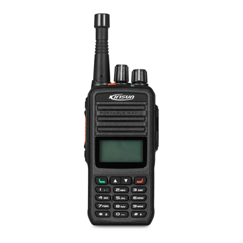
  9. Kirisun PT4200-01 User manual

Kirisun PT4200-01 User manual

TUNE UP PROCEDURE FOR PT4200-01
zTHE BUILT-IN CHANNELS ARE 15 CHANNELS +1 SCAN
CHANNEL
zTHE RANGE OF FREQUENCY IS 421--470MHz .
Before test/debugging, make sure all the equipments have been well connected to the
ground.
Before test/debugging, make sure the antenna output terminal has been connected
properly to the corresponding devices and load.
The transmitter output must pass RF power attenuator before being connected to the
standard signal source/ frequency deviator/ frequency spectrum.
When testing the receiver, make sure not to conduct transmitting operation.
When in debugging/testing/service, make sure static free measures for human body and
equipments.
1.1 Service Equipment and Software.
The following equipments and software in Table 1.1 are necessary for the service and test
of the radio.
Table 1.1 For Test and Service:Equipment and Software
No. Item Specifications
1 Computer Higher than P2, compatible with IBM PC,WINDOWS 98/ME/2000/XP
2 Programming
Software
KSP-20
3 Programming
Line
KSPL02
4 Cloning Line KCL01
5 DC Regulated
Power
Output voltage:7.5V, Output current:≥5A
6
RF power
meter
Test range:0.5---10W
Frequency range:100MHz—500MHz
Impedance:50Ω
SWR≤1.2
7
Frequency
Meter
Frequency range:0.1—600MHz
Frequency precision: Higher than ±1×10⁻⁶
Sensitivity:Higher than 100mV
8 Frequency
Deviator
Frequency range:DC—600MHz
Test range:0--±5kHz
9 Digital Input impedance:Higher than 10MΩ/V DC ,with the ability of testing voltage,
Multimeter current, impedance.
10 Audio Signal
Generator
Frequency range:2---3000Hz
Output level:1---500mV
11 RF power
Attenuator
Attenuation:40dB or 50dB
Supporting power:Bigger than 10W
12 Standard
signal source
Frequency range:10MHz---1000MHz
Output level:0.1uV~32mV (-127dBm~-17dBm)
13 Oscillograph Frequency range:DC~20MHz
Test range:10mV~20V
14 Audio
voltmeter
Test range:10mV~10V
The equipments in item 6, 7, 8, 10, 11, and 12 can be replaced by a comprehensive test
instrument.
MIC JACK
SPEAKER JACK
PTT
/
RXD
MIC
5MS
GND
TXD
SP
Figure 1.1 External Speaker/Mic Connector Definition
1.2 Debugging Items
During the course of maintenance, the radio needs to be tested and debugged after
replacing components. Some certain radio parameters can be modified (computer mode)
with our KSP 20 programming software. The modifiable parameters are as follows:
1) Frequency difference
2) TX power
3) Low battery power warning threshold
4) Squelch level
5) CTCSS frequency deviation
6) DCS frequency deviation
Debugging Procedures
a. Enter the computer test mode.
b. Select the “Test Mode” option to enter the computer test mode.
c. Select the options that you want to adjust and adjust the parameters on the
computer.
d. After adjustment, exit the computer test mode.
1.3 Debugging
1.3.1 VCO Modification
Turn off the power saving mode. Set the frequency at the low frequency (see Table 1.2). In
receiving status, test the PD power with the digital multimeter. Adjust the trimming
capacitor C180 to make the PD power at 1V±0.1V.
Set the TX frequency at high frequency, press the PTT button, test the PD power with the
digital multimeter. The power should lower than 3.5V.
1.3.2 PLL Frequency Adjustment
Under the computer test mode, select “frequency tune” option and click “adjustment” to
enter. Adjust the TX frequency among 0~255 to the specified value. (Frequency error
should less than 200Hz.)
1.3.3 TX Frequency Adjustment
Under the computer test mode, select “high power, low frequency” and click “adjustment”
to enter. Adjust the TX power among 0~255 to 4W. And watch the working current and
make sure it not higher than 1.5A.
Adjust “high power, medium frequency”, “high power, high frequency’ to set the TX power
at 4W.
1.3.4 TX Low Power Warning
Adjust the power to 6.8V.
Under the computer test mode, select “the low power threshold”, and click “adjustment” to
enter. Adjust the figure among 0~255 to make the red light flash.
1.3.5 Frequency Deviation Adjustment
Input 100mV, 1000Hz audio signals from the radio MIC, and adjust the potentiometer VR2
to set the TX frequency deviation at ±2.2kHz.
1.3.6 DCS TX Signal Wave Shape and Frequency Adjustment
Under the computer test mode, select “ DCS wide band modulation”, and click
“adjustment” to enter. Adjust the potentiometer VR1, and watch the demodulation signals.
The wave shape should be smooth (close to square wave) and then adjust the figure to
set the frequency deviation at 0.35kHz.
1.3.7 CTCSS Frequency Deviation Adjustment
Under the computer test mode, select “CTCSS wide band modulation”, and click
“adjustment” to enter. Adjust the figure to set the frequency deviation at 0.35kHz.
1.3.8 Receiver Sensitivity
Repeat adjusting L9, L10, L6, and L5 to make the frequencies at highest sensitivity.
1.3.9 Receiver Squelch Setting
Under the computer test mode, select “the 9
th
squelch” and click “adjustment” to enter.
Input the receiver with the signals of 1kHz modulation frequency, 3kHz frequency
deviation, and -117dBm level. Adjust the figure to make the green light flash.
Under the computer test mode, select “the 3
rd
squelch” and click “adjustment” to enter.
Input the receiver with the signals of 1kHz modulation frequency, 3kHz frequency
deviation, and –124dBm level. Adjust the figure to make the green light flash.
1.4 Debugging
The above debugging refers to Table3, Table4, and Table 5.
Table 1.3 Voltage Controlled Oscillator (VCO)
Item Test Condition Te s t
Equipment Te s t P o i n t Adjustment
Part Requirement Note
Setting Battery Power:7.5V Digital Multimeter PD
CH:RX Low Frequency C180 1.0V±0.1V Adjustment
CH:RX High Frequency Lower than
3.5V Watch
CH:TX Low Frequency C181 1.0V±0.1V Adjustment
Locked
Power
CH:TX High Frequency
Lower than
3.5V Watch
Table 1.4 Receiver
Item
Test Condition
Test Equipment
Test
Point Adjustment Requirement Note
Band
Pass
Filter
Spectroanalizer/
Comprehensive
Test
Device
Before
Mixing
Computer
Test Mode
Not
recommend
the user to
adjust it!
Audio
Level
Test
Frequency :
MF
Antenna Input:
RF OUT :
-53dBm(501µV)
MOD:1kHz
DEV:±3.0kHz
Audio Load :
16Ω
(Turn the
volume knob
clockwise)
Audio power
>0.3 W
Inner
speaker
power >
1.2W
Sensitivity
CH:MF
CH:LF
CH:HF
RF OUT:
-116dBm(0.35µV)
MOD:1kHz
DEV:±1.5kHz
Computer
Test Mode
SINAD:
12dB or
higher
Squelch
Activation
Sensitivity
CH:Receiving
Center
Frequency
RF Audio Signal
Generator
Oscillator
Audio Voltmeter
Distortion Test
Device
/Comprehensive
Test Device
Speaker
Connector
After
adj
ustment,
squelc
h
9th
RF OUT :
-117dBm
activation is
normal.
3rd
RF OUT :
-124dBm
Computer
Test Mode
After
adjustment,
squelch
activation is
normal.
Table 1.5 Transmitter
Item Test Condition Test Equipment Te s t
Point Adjustment Requirement Note
TX
Frequency
Frequency Meter/
Comprehensive Test
Device
Computer
Test Mode Within ±200Hz
DCS Wave
Shape
(Balance)
Oscillator /
Comprehensive Test
Device
VR1
Wave shape is
close to
smooth square
wave.
Power
Power Meter/
Comprehensive Test
Device/
Ammeter
Computer
Test Mode Adjust to 4.7W Within±0.2W
Maximum
Modulation
Frequency
Deviation
CH :TX Center
Frequency
AG:1kHz/220mV
VR2 Adjust to
±2.2kHz ±200Hz
Modulation
Sensitivity
CH :TX Center
Frequency
AG:1kHz/22mV
Frequency Deviation
Meter/ Comprehensive
Te s t
Device
Checking
frequency:
1.1kHz~1.9kHz
CTCSS
DEV CTCSS:67Hz
Frequency Deviation
Meter/
Comprehensive Test
Device
Computer
Test Mode
Adjust
to±0.35kHz ±50Hz
DCS DEV DCS:023N
Frequency Deviation
Meter/
Comprehensive Test
Device
Antenna
Computer
Test Mode
Adjust
to±0.35kHz ±50Hz
Battery
Power
Warning
Battery Terminal:
6.8V
Computer
Test Mode
After
adjustment, the
indicator
flashes.

Other Kirisun Two-way Radio manuals

Kirisun DP586 User manual

Kirisun

Kirisun DP586 User manual

Kirisun DP405 User manual

Kirisun

Kirisun DP405 User manual

Kirisun DP580 User manual

Kirisun

Kirisun DP580 User manual

Kirisun DP770 Quick start guide

Kirisun

Kirisun DP770 Quick start guide

Kirisun DP99001 User manual

Kirisun

Kirisun DP99001 User manual

Kirisun PT4200 User manual

Kirisun

Kirisun PT4200 User manual

Kirisun PT6500-02 User manual

Kirisun

Kirisun PT6500-02 User manual

Kirisun DP485 User manual

Kirisun

Kirisun DP485 User manual

Kirisun DP585 User manual

Kirisun

Kirisun DP585 User manual

Kirisun UP305 User manual

Kirisun

Kirisun UP305 User manual

Kirisun PT4208 User manual

Kirisun

Kirisun PT4208 User manual

Kirisun Omni Pro T65 User manual

Kirisun

Kirisun Omni Pro T65 User manual

Kirisun PT650001A User manual

Kirisun

Kirisun PT650001A User manual

Kirisun DP480-01 User manual

Kirisun

Kirisun DP480-01 User manual

Kirisun UP405S Instruction manual

Kirisun

Kirisun UP405S Instruction manual

Kirisun FP560 User manual

Kirisun

Kirisun FP560 User manual

Kirisun PT5200-01 User manual

Kirisun

Kirisun PT5200-01 User manual

Kirisun TM84001 User manual

Kirisun

Kirisun TM84001 User manual

Kirisun T60 User manual

Kirisun

Kirisun T60 User manual

Kirisun FP520 User manual

Kirisun

Kirisun FP520 User manual

Kirisun FP460 User manual

Kirisun

Kirisun FP460 User manual

Kirisun GP700 User manual

Kirisun

Kirisun GP700 User manual

Kirisun FP520S User manual

Kirisun

Kirisun FP520S User manual

Kirisun DP480 User manual

Kirisun

Kirisun DP480 User manual

Popular Two-way Radio manuals by other brands

Motorola CLS1110 user guide

Motorola

Motorola CLS1110 user guide

Hy-Gain hy-range II 671B-PR owner's manual

Hy-Gain

Hy-Gain hy-range II 671B-PR owner's manual

Uniden UH044SX operating guide

Uniden

Uniden UH044SX operating guide

Ericsson M-RK Maintenance manual

Ericsson

Ericsson M-RK Maintenance manual

Global T481838 owner's manual

Global

Global T481838 owner's manual

Motorola RMU2080d user guide

Motorola

Motorola RMU2080d user guide

Entel DT900FF Quick start user guide

Entel

Entel DT900FF Quick start user guide

Vertex VX-5500 operating manual

Vertex

Vertex VX-5500 operating manual

Midland X-TRA TALK LXT500 series owner's manual

Midland

Midland X-TRA TALK LXT500 series owner's manual

Midland LXT380VP3 Specifications

Midland

Midland LXT380VP3 Specifications

PRESIDENT JOHNSON II owner's manual

PRESIDENT

PRESIDENT JOHNSON II owner's manual

DICKIE TOYS SLIDE & SOUND 18108 operating instructions

DICKIE TOYS

DICKIE TOYS SLIDE & SOUND 18108 operating instructions

Ritron NT Series user manual

Ritron

Ritron NT Series user manual

Hytera PD782 user guide

Hytera

Hytera PD782 user guide

RELM RMV800 Service manual

RELM

RELM RMV800 Service manual

Cobra MicroTalk CXT125C user guide

Cobra

Cobra MicroTalk CXT125C user guide

Motorola TALKABOUT T5025 user guide

Motorola

Motorola TALKABOUT T5025 user guide

Ricatech PR190 user manual

Ricatech

Ricatech PR190 user manual

manuals.online logo
manuals.online logoBrands
  • About & Mission
  • Contact us
  • Privacy Policy
  • Terms and Conditions

Copyright 2025 Manuals.Online. All Rights Reserved.