KiSS Sidekick User manual

MSL 72.162 GEM Sidekick R.2
1

MSL 72.162 GEM Sidekick R.22
Introduction GEM Sidekick SCR
The GEM Sidekick SCR is the latest addition to the KISS rebreather family. Like all KISS systems, it is durable, reliable,
easy to use, and economical. The Sidekick brings a few more bonuses to the table. The compact design allows the
Sidekick to be used in a number of ways: Side-mount rebreather, Bailout rebreather or simple add on Gas Extender. The
Sidekick requires no modification to fill all of these roles.
The KISS GEM Sidekick uses the patented KISS Gas Extending Mechanism (GEM). The GEM system will allow the gas
in your cylinder to last three times as long as conventional SCUBA. Other benefits include small size, lightweight, fewer
parts and less complexity than diving a fully closed circuit rebreather. The Sidekick still provides many of the benefits that
rebreather diving offers: warm, moist gas to breathe, no noisy rush of bubbles to scare fish away, and the longer No-
Decompression-Limits of diving Nitrox.
This manual describes the operation, assembly, breakdown and maintenance of your new KISS GEM Sidekick. There
are sections for each system component. Later sections discuss some of the dive operations and troubleshooting.
To safely use any dive equipment, the diver must fully understand the equipment. That is why this manual is required
reading. Not only does the longevity of your new Sidekick depend on your reading and understanding this manual, but
your safety depends on proper understanding and operation of all your dive gear.
Information in this manual is subject to change.
Please visit our website, www.kissrebreathers.com for updated manuals.
Conventions
The warning signs and the simple icons shown here are listed in order for you to use this product safely and correctly as
well as to prevent risk of injury to you and to others.
Indicates matters in which an imminent or possible risk of serious injury or death may arise
as a result of incorrect operation.
Indicates matters which must be closely considered as they affect the proper use and or
maintenance of the equipment and could affect the safety of the diver.
Safety Guidelines
Warning
KISS GEM Sidekick diver’s must read this manual.
In order to fully understand the KISS GEM Sidekick Gas Extender, the components, how
they work, how to handle and treat them, diver’s must read this manual in full. This should
be done prior to diving or servicing the unit.
Pay special attention to all notes and warnings; they must be read and understood. Failure
to do so may cause equipment damage, serious injury, or death.
This manual contains a checklist of inspections and tests that must be performed prior to
each dive. Do not dive unless you have completed this checklist. Do not dive unless the
equipment has passed all of the tests. Failure to perform all inspections and tests, or
ignoring a failure may cause serious injury or death.
You must be 18 years of age in order to purchase and dive a KISS GEM Sidekick diving
Warning
Note

MSL 72.162 GEM Sidekick R.2
3
system.
You must be properly trained to dive this equipment. Diving this equipment without proper
training may cause serious injury or death.
This manual in no way replaces the training required for diving this equipment. Proper
training is extremely important as is gathering the proper experience.
Only dive within the limits of your certification.
This equipment should be serviced annually by a service technician. Service may be
required more often if you dive frequently, or water has entered the equipment.
Always monitor your PPO2 when breathing from this equipment. This should be checked
once a minute at depth and continuously during an ascent.
Do not breathe from this equipment while swimming on the surface.
Do not breathe from this equipment at a depth less than 20 ft.
During training this equipment may be used in a pool, but only with 40% Nitrox, and only
under supervision.
Do not use diving gasses outside the limits of your certification.
All information in this manual is subject to change. Please visit our website,
www.kissrebreathers.com/manuals.html for updated versions.
Assumption of
Risk
The warnings & notes in this manual are not a joke!
Participation in rebreather diving can result in serious injury or death.
Before beginning your dive, you must consider the risks involved. The GEM Sidekick
consists of many parts. All of these components will eventually fail. Careful maintenance,
assembly, and testing will not prevent this from happening. At best, it will delay the failure.
The KISS GEM Sidekick is not automatic in any way. It requires constant monitoring, a
complete awareness of the potential problems likely to be encountered, and full knowledge
of how to deal with whatever problems may occur. If you do not have adequate training,
equipment, physical conditioning, and a proper mindset, do not get in the water.
The diver, YOU, has the final responsibility for his or her own safety and actions while
using this rebreather. All components of the KISS GEM must be in good working order and
be properly assembled and tested to reduce the risk of failure. Regardless of the training
and experience of the diver and the reliability of the rebreather the risk of serious injury
and/or death can never be reduced to zero.
This manual is not a complete text on the maintenance and operation of the KISS GEM
Sidekick. The diver must complete a proper training course covering the maintenance,
testing and operation of the semi-closed rebreather before diving this equipment. The
rebreather can malfunction while diving even when properly assembled and having passed
all pre-dive tests. Only carrying adequate gas and having the training and skills necessary
to switch to open circuit gas, can reduce, but never eliminate, the risk of equipment failure.

MSL 72.162 GEM Sidekick R.24
Table of Contents
IntroductionGEMSidekickSCR.................................................................................................................................2
Conventions.......................................................................................................................................................................2
SafetyGuidelines.............................................................................................................................................................2
UnpackingtheSidekick.................................................................................................................................................6
TheoryofOperation.......................................................................................................................................................7
GasSelection....................................................................................................................................................................................8
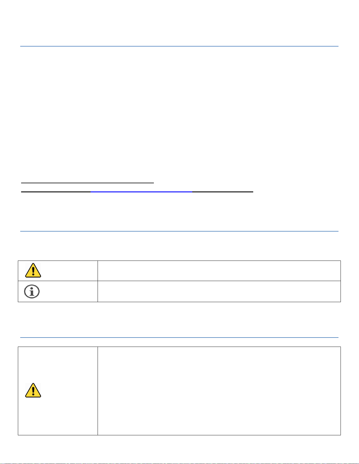
SystemComponents.......................................................................................................................................................9
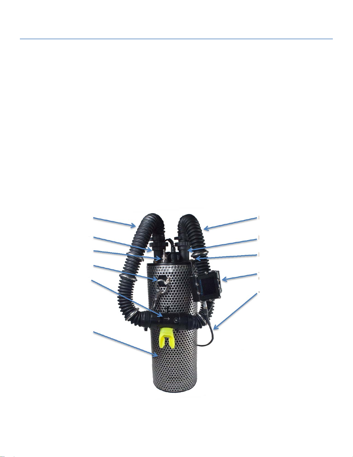
Mouthpiece.......................................................................................................................................................................................9
LoopHoses.....................................................................................................................................................................................11
ScrubberCanisterandScrubberHeadAssembly.............................................................................................................11
ScrubberCanister.........................................................................................................................................................................................12
InhaleandExhaleTowers.........................................................................................................................................................................14
OverPressureValve(OPV).......................................................................................................................................................................14
OxygenDisplayCable..................................................................................................................................................................................14
GasSupplyConnection...............................................................................................................................................................................14
VacuumBreak................................................................................................................................................................................................14
..............................................................................................................................................................................................................................14
DemandValve(ADV)..................................................................................................................................................................................14
SensorHolder/SensorScreen...............................................................................................................................................................1 5
CounterlungandCounterlungCover....................................................................................................................................16
OxygenMonitor............................................................................................................................................................................17
OxygenSensors
.............................................................................................................................................................................17
GearAttachment..........................................................................................................................................................................18
SystemAssembly...........................................................................................................................................................19
Checklists........................................................................................................................................................................................19
DisplayCalibration......................................................................................................................................................................19
CalibratetoAir...............................................................................................................................................................................................19
VerifyCalibrationwithNitrox.................................................................................................................................................................20
KISSFCPPO2DisplayCalibration.........................................................................................................................................................20
ShearwaterGEMCalibration...................................................................................................................................................................20
PackingtheScrubber.................................................................................................................................................................20
LoadingtheMicroporeEAC.....................................................................................................................................................................20
..............................................................................................................................................................................................................................21
..............................................................................................................................................................................................................................21
..............................................................................................................................................................................................................................21
..............................................................................................................................................................................................................................21
..............................................................................................................................................................................................................................21
LoadingGranularCO2Absorbent..........................................................................................................................................................21
............................................................................................................................................................................................................22
............................................................................................................................................................................................................22
AttachingtheCounterlungandCounterlungCover........................................................................................................22
MouthpieceandLoopHoseConnection...............................................................................................................................23
MouthpiecePositiveandNegativeTesting........................................................................................................................................23
AttachtheLoopHosestotheScrubberHead...................................................................................................................................23
PositiveandNegativeTest.......................................................................................................................................................24
FiveMinutePre‐Breathe...........................................................................................................................................................25
DivingProcedures.........................................................................................................................................................25
Selectthepropergas..................................................................................................................................................................25

MSL 72.162 GEM Sidekick R.2
5
OpenLoop.......................................................................................................................................................................................26
BuddyChecks................................................................................................................................................................................26
TrimandCounterlungAdjustment.......................................................................................................................................26
BreathinginDifferentOrientations......................................................................................................................................26
Descent............................................................................................................................................................................................27
AtDepth...........................................................................................................................................................................................27
Ascent...............................................................................................................................................................................................27
GasSwitching.................................................................................................................................................................................28
FloodRecovery.............................................................................................................................................................................28
Post‐DiveProcedures..................................................................................................................................................30
Doffing..............................................................................................................................................................................................30
BetweenDives...............................................................................................................................................................................30
BreakdownandCleaning..........................................................................................................................................................30
Storage.............................................................................................................................................................................................31
MaintenanceandService............................................................................................................................................32
HoseAttachmentTowers..........................................................................................................................................................32
MouthpieceDischargePortDiaphragmsandButtons...................................................................................................32
CareforyourFischerConnectorandCable........................................................................................................................32
RecommendedSpareParts......................................................................................................................................................33
Troubleshooting............................................................................................................................................................34
FailedPositiveorNegative.......................................................................................................................................................34
WaterintheLoop........................................................................................................................................................................34
BubblingOPV,ApeksExhaustValve.....................................................................................................................................34
ADVStiffinTriggering...............................................................................................................................................................35
HighWorkOfBreathing............................................................................................................................................................35
DisplayTroubleshooting...........................................................................................................................................................36
TrainingandMinimumTrainingStandards........................................................................................................37
Appendix..........................................................................................................................................................................40
ScrubberCartridgeDuration...................................................................................................................................................40
SidekickAssemblyChecklist....................................................................................................................................................41
SidekickPre‐diveChecklist......................................................................................................................................................43
PostDiveCheckList‐SidekickDisassembly.....................................................................................................................44
ShearwaterGEMOperation......................................................................................................................................................45
ConfiguringtheShearwaterforSemi‐ClosedOperation...............................................................................................45
Warranty..........................................................................................................................................................................46
Specifications..................................................................................................................................................................47
SidekickCCR–Addendum.........................................................................................................................................48
MOUTHPIECE.................................................................................................................................................................................48
MANUALOXYGENADDITIONSYSTEM..................................................................................................................................48
AdjustingtheO2FlowRate......................................................................................................................................................................50
ManualAddValveTroubleshooting.....................................................................................................................................................52
FIRSTSTAGE..................................................................................................................................................................................53

MSL 72.162 GEM Sidekick R.26
Unpacking the Sidekick
Unpack your GEM Sidekick using the parts list below, ensure that all components have been received and there hasn’t
been any shipping damage. If anything seems to be damaged from shipping, please contact either your dealer or the
KISS Rebreathers offices in a timely fashion so that we may replace your damaged parts.
The KISS GEM Sidekick diving system you have purchased is for recreational diving and should be configured as
instructed in this manual.
GEM SIDEKICK DIVING SYSTEM INCLUDES:
1 Scrubber Head: Includes 2 hose attachment towers, 1 exhaust valve, ADV system, 1 gas connection fitting, 2
scrubber canister O-rings (installed), and 2 counterlung O-rings (installed)
1 GEM Canister (granular): Includes threaded tube, base with O-rings (installed), spring, white mesh pad, diffuser
plate.
GEM Canister – Cartridge Components (Included only upon request at the time of order): Base crosspiece,
gasket & circ clip installed inside custom machined canister tube.
1 Counterlung with Counterlung Cover: Includes 4 knurled attachment nuts, 2 rigging clips.
2 17 inch loop hoses
1 sensor holder and 1 sensor screen.
1 display cable with Fischer connector: Hardwired to the scrubber head and compatible with KISS FC PPO2
display, Shearwater computers, and other appropriate computers or displays.
1 mouthpiece (DSV) with 2 black circ clips: DSV and circ clips ship secured to the loop hoses for shipping.
Quick Disconnect (QD) Female: Connects supply gas from your first stage regulator. (QD only, LP hose not
included)
1 CD with manual. This will be in your envelope with your warranty card
.
ADDITIONAL GEAR REQUIRED FOR DIVING:
LP hose: required to secure the Female QD to your first stage. Consult dealer or Instructor to determine what
length is correct for you.
First stage with pressure gauge and second stage.
Personal gear: mask, fins
NITROX ready dive cylinder
Buoyancy Compensator: suitable for the diving environment.
Weights
Exposure suit: suitable for diving conditions (suit, boots, gloves, hood)
Dive computer/Dive timer and depth gauge
3 Oxygen sensors (K-22D recommended)

MSL 72.162 GEM Sidekick R.2
7
Theory of Operation
When the diver exhales into the GEM Sidekick mouthpiece, one third of the gas is diverted out of the vent holes in the
mouthpiece and into the water. Two thirds of the breath passes through the exhale loop hose and into the exhale
counterlung. When the diver inhales, the gas is drawn out of the counterlung, through the scrubber, up through the inhale
loop hose, and back to the mouthpiece. The scrubber contains a material that chemically bonds with the Carbon Dioxide
(CO2) in the exhaled breath and removes it. At the end of the inhale cycle the remaining gas volume is supplied by an
Automatic Demand Valve (ADV) with gas from the SCUBA cylinder. This fresh gas replaces the Oxygen (O2) in the loop.
The Oxygen level in the GEM Sidekick is measured by three Oxygen sensors located in the scrubber head.
The GEM Sidekick (like any rebreather) can be broken down into the follow functional parts:
Mouthpiece
Loop Hoses
Counterlung
Scrubber Canister
Oxygen Addition
Oxygen Monitor
As a Passive Semi-Closed Circuit Rebreather (pSCR), the Oxygen addition is achieved by venting a fraction of the diver’s
exhaled breath, and adding Nitrox to make up the vented volume. In this way each breath (on inhale) contains one third
fresh Nitrox, and two thirds scrubbed exhaled gas.
Inhale Loop Hose
Inhale Hose Tower
Gas Connection
ADV Access
GEM Mouthpiece
Counterlung Cover
Exhale Loop Hose
Exhale Hose Tower
Knurled Nuts
PPO2 Monitor
(Shearwater)
Oxygen Display Cable
Figure 1: KISS GEM Sidekick

MSL 72.162 GEM Sidekick R.28
GasSelection
When diving the GEM Sidekick, each inhaled breath is composed of a fraction of fresh gas from the supply cylinder and
the remainder of the gas is the diver’s exhaled breath after being scrubbed of Carbon Dioxide (CO2). The fraction of
Oxygen (O2) remaining in a diver’s exhaled breath will vary based on workload, the diver’s metabolism, & the diver’s size.
This means that a diver and his buddy may have different PPO2/FiO2 while using the same nitrox mixture.
The fraction of O2 inhaled will be less than the fraction of O2 in the supply cylinder. This is known as the Fraction of
Inspired O2 or FIO2. There is no way to calculate exactly what this FIO2 will be as every person is unique. This is one
reason it is very important to always monitor the Partial Pressure of Oxygen (PPO2) in the breathing loop.
While we do not know the exact percentage of O2 a diver will metabolize with each breath, we do know that the higher the
fraction of O2 in the supply cylinder, the higher the FIO2 will be. We also know that the greater the ambient pressure
(depth of the water) the higher the Partial Pressure of Oxygen (PPO2) will be for a given FIO2.
A low percentage of Nitrox combined with a high workload and shallow water can lead to a dangerously low PPO2
(Hypoxia). KISS testing has shown that diver’s using a minimum of 32% nitrox will provide diver’s with a safe breathing
mixture. However this may not be true for all diver’s in all situations. Be certain to know what you are breathing. The
shallower the diver is, the lower the PPO2/FiO2 may drop. Also, it will drop quickly on the surface.
For this reason it is very important that level 1 Sidekick diver’s use a minimum of 32% nitrox. Diving a lower percentage
will likely provide the diver with a hypoxic mix on ascent and in shallow water. Those diver’s that wish to use nitrox
mixtures with a lower percentage of O2 must take level 2 GEM training. At this level they will be taught to use a
secondary gas mixture which would enable them to have the appropriate mix for ascent and shallow water.
To prevent the risk of hypoxia in shallow water, diver’s 20 feet or shallower should be breathing either open circuit or open
loop. This should be done for both the ascent and decent. It is important that rebreather diver’s always know what they
are breathing. The PPO2/FiO2 should be checked every minute, and continuously on ascent.
Gas selection must also consider the fraction of Nitrogen (N2) in the inhaled breath. Since the diver metabolizes a
fraction of the O2 with each breath, the fraction of N2 goes up as the fraction of O2 goes down. This increases the N2
absorbed in the diver’s tissues, and reduces our No Decompression Limit. Again, a higher Nitrox percentage will reduce
the N2 in the gas, but the diver must not exceed the MOD of the Nitrox.
The following Safety Guidelines must be followed to prevent serious injury or death:
Always know your PPO2!
Monitor your PPO2 once a minute during the dive.
Never breathe off of the Sidekick mouthpiece without monitoring the PPO2.
Always use the highest Nitrox percentage for the planned dive depth without exceeding
the MOD.
The higher the mix the less chance of Hypoxia (the shallower the MOD); the lower the
nitrox mix the greater chance of hypoxia (the deeper the MOD).
Never dive with less than 32% Nitrox.
Never breathe on the GEM Sidekick while on the surface, or swimming on the surface.
Switch to open circuit or open loop when shallower than 20 ft.
While performing system testing that involves breathing from the GEM mouthpiece,
constantly monitor the PPO2. Especially during the five minute pre-breathe.
Never dive the GEM Sidekick outside your certification level. Decompression diving is
risky and requires specialized training.
The following Safety Guidelines must be followed to prevent serious injury or death:
Never let the FIO2 drop below 21%
If the FIO2 drops below the planned level, switch to open circuit to reduce the risk of
decompression sickness.
Never use the GEM Sidekick in a swimming pool without a minimum 40% nitrox in the
cylinder AND also direct supervision by a GEM Sidekick instructor.
The GEM mouthpiece will not vent properly if the unit is not submerged in water, which
means fresh nitrox will NOT be added, which could make the breathing mixture hypoxic.
Level 1 KISS GEM Sidekick divers are certified to use Nitrox mixtures from 32% Nitrox to 40% Nitrox in no decompression
dives. As stated above, use the highest Nitrox percentage available without exceeding the MOD. KISS recommends 36%
or higher.
Warning
Warnin
g

MSL 72.162 GEM Sidekick R.2
9
System Components
The GEM Sidekick is composed of a number of component parts. Each component performs a discrete function as
described in the Theory of Operations. This section discusses each component in more detail, including the parts,
function, assembly and care.
Mouthpiece
The mouthpiece is the key to the GEM
Sidekick diving system. The design
allows a fraction of the gas to be vented
from the breathing loop every time the
diver exhales. Whether relaxed and not
breathing hard, or under a heavy
workload, the mouthpiece will always
vent the same percentage.
The mouthpiece is shipped fully
assembled, tested and ready to dive.
The black plastic circ clip’s are used to
attach it to the loop hose, hose
attachment’s. When you receive your
GEM Sidekick, the mouthpiece will be
attached to the loop hoses, with the circ
clip’s in place.
When the mouthpiece discharges the gas, a small stream of bubbles will vent. These bubbles will come from the
discharge ports on the mouthpiece. Since the diver can see the bubbles, it will be immediately obvious if there is a
problem and no bubbles are venting. If this happens, the diver should also notice that the ADV is not adding gas. It won’t
add gas, as the volume in the system has not been depleted.
If the mouthpiece is not venting, the gas mixture you are breathing could drop to a dangerous
level. This could cause injury or death, especially at shallower depths!
Dive Surface Valve (DSV)
On the front of the mouthpiece, also known as the Dive Surface Valve, is a lever that activates the DSV. In the up
position, the valve is open and the diver’s exhaled breath will enter the exhale loop hose and counterlung. In the down
position the valve is closed, and the diving loop is sealed. In general, whenever the mouthpiece is not in the diver’s
mouth, the valve should be closed. This prevents water from entering the mouthpiece and the Sidekick. While
underwater, always close the DSV before removing the mouthpiece from your mouth.
Purging the mouthpiece
Just like any other SCUBA mouthpiece, when it’s been out of your mouth (particularly underwater) it needs to be purged
before use. In this case that means you need to be purge the mouthpiece prior to opening the DSV. To do this, put the
GEM Sidekick mouthpiece in your mouth and exhale forcefully. This will push the water out of the vent hole. You only
need to do this for a few seconds as it is a minute amount of water. Once you see bubbles, the water is gone. After
purging push the lever to the open position and then you may continue to breathe on the loop.
Only a qualified GEM service technician should attempt to service the GEM Sidekick
mouthpiece. Do not attempt to service the mouthpiece without the proper training.
DSV
Hose
Attachment
O-rings
Diaphragm
and Button
Valve
Bite Piece
Circ-Clip
Figure 2: GEM Mouthpiece and Circ-Clip
Warning
Warning

MSL 72.162 GEM Sidekick R.210
While doing the above exercise, be certain to not cover the vent hole with your hand as you move the lever. Covering the
vent hole with your hand will prevent it from purging the water.
Diaphragms and Buttons
The Sidekick mouthpiece has 3 discharge port diaphragms and buttons. These allow the mouthpiece to vent a fraction of
the diver’s breath while preventing water from entering the mouthpiece. To perform this function properly the diaphragms
must lay flat against their seat. If the attachment screws are too tight, or the diaphragm has been dislodged, it needs to
be reseated prior to use. Diaphragms and buttons should be visually inspected prior to every dive to ensure that the
diaphragms are sitting flat, and properly placed.
The discharge port diaphragms are an essential component of the mouthpiece. It is important that they are in good
working order. When visually inspecting your mouthpiece, ensure that they are not torn or damaged in any way, and that
they are lying flat. If they are not lying flat, either flip the diaphragm over or install a new one otherwise water can enter the
breathing loop.
Prior to removing the screw and button that holds the discharge port diaphragm, note how tight the screw is. It is important
that the screw is not over tightened when reassembling the mouthpiece. Watch closely when tightening this screw. If the
diaphragm lifts at all, on any edge, back the screw off.
If you have a failed discharge port diaphragm, it will bubble constantly. This may also allow
excess water into the exhale hose.
Right side inner valve assembly & left side mushroom valve
The right side of the valve houses the inner valve assembly and the outer valve
assembly. The inner valve assembly is the inner piece that moves back and forth. The
outer valve assembly is the component that is screwed to the right side housing.
If the inner valve assembly starts to stick either open or closed, it is likely that the
mouthpiece either needs to be cleaned or that some lubricant has worked its way into
the area, If a single drop of lubricant is in that area in which the valve moves back and
forth, it could cause the valve to stick.
If this happens, remove the outer and inner valve assembly. Using a perfectly clean
cloth - there can’t be any lubricant on it at all - carefully clean the inner part of the
mouthpiece. All traces of lubricant must be removed. Clean the inner valve assembly
and then reattach the outer assembly.
When inserting the inner piston back into the inside of the mouthpiece, be certain
that you put it in the correct way. It will not work if it is upside down! As per the
photo, the inner piston should have the open area facing out. The open area needs to face the open area of the outer
piston for it to work properly.
If the valve gets stuck, it could happen in the open or closed position. Also, be certain that if
the inner piston is removed, that it is inserted correctly upon reassembly. If the inner piston
is inserted upside down, the valve will not work!
Prior to diving, visually check the left side, or inhale mushroom valve and ensure that it is lying properly and not damaged.
Also ensure that it is facing the correct direction with the gas flow going from left to right. Gently shake the mouthpiece to
ensure that the right side valve components are moving freely back and forth. These parts must move freely for the
mouthpiece to work properly. If they don’t move freely the mouthpiece must be serviced. Having the mouthpiece serviced
by a trained GEM service technician is important. If the servicing of the valve is not done properly, and lubricant is applied
to the wrong parts, the valve will stick and not work. Lubricant in the right side valve area will cause the inner valve to
stick either open or closed.
If the right side one-way valve sticks open, you will notice excess bubbles venting from the mouthpiece. The unit should
not be dove in this manner as the gas is not flowing properly and could cause a problem with carbon dioxide. If the valve
sticks closed, it would be difficult to exhale. A sharp exhale would dislodge it, but the proper action would be to end the
dive and service the mouthpiece.
If the mouthpiece right side valve is sticking, do not dive the rebreather. Have the mouthpiece
served immediately. Diving the GEM Sidekick with a mouthpiece that is not functioning
properly could cause injury or death!
Note
Warnin
g
Warnin
g
Figure 3: DSV Right Side Valve Assembly

MSL 72.162 GEM Sidekick R.2
11
The KISS GEM mouthpiece is a key component to this diving system. Proper care and
servicing is essential in order to maintain proper working order. Key areas of importance
include, but are not limited to, ensuring the piston is moving properly, the mushroom valve is
working as it should, and the discharge port diaphragms are sitting flat and not damaged.
Improper use and/or care may result in serious injury or death!
LoopHoses
The Sidekick loop hoses perform the simple task of connecting the
mouthpiece to the scrubber head. Both hoses are of the same length,
and are interchangeable. The ends of the hoses should be handled
carefully to prevent damage to the O-rings and sealing surfaces.
Inspect the O-rings and surfaces prior to assembly. Clean the surface
and add a small amount of silicone grease to aid in assembly.
The loop hoses are shipped fully assembled with the ballast rings,
hose stubs and hose attachments in place. The ballast rings may be
moved to suit each diver. The instructor will aid the student in ensuring the rings are properly placed.
The loop hose material will last a long time if properly maintained. As with all dive gear they should not be left out in the
sun as it degrades the rubber. They should be rinsed regularly, and sanitized and rinsed after each dive day. They
should be dried thoroughly before putting them away.
The loop hoses and quick disconnect hose stubs are important components on the KISS
GEM Sidekick diving system. It is important that they be treated properly, cleaned and
replaced if damaged. Diving the Sidekick with damaged hoses or damaged hose stubs can
lead to serious injury or death.
ScrubberCanisterandScrubberHeadAssembly
The Scrubber Canister & Scrubber Head Assembly is the central hub of the Sidekick diving system. Many components
attach to it, and many functions are performed by it. Let’s identify all of the parts then describe each one in detail.
The Scrubber Canister consists of several components. There are two versions; the granular scrubber canister and
the cartridge scrubber canister. The Sidekick is shipped standard with the granular scrubber canister assembly. At the
time of order, the cartridge scrubber canister assembly may be requested and the components included in the shipment.
Granular Scrubber Canister:
Scrubber base
Scrubber Canister Tube
Scrubber Head Assembly
Figure 5: Scrubber Canister & Scrubber Head Assembly
Fi
g
ure 4: Loop Hoses with Ballast rin
g
s
Warnin
g
Warnin
g

MSL 72.162 GEM Sidekick R.212
Scrubber Canister
Scrubber Base
White Mesh Pad, & Diffuser Plate
Spring
Scrubber Head Assembly
Cartridge Scrubber Canister:
Scrubber Canister with gasket and metal circ clip
Scrubber Base
Base Cross Support
Scrubber Head Assembly
Located on the top of the Scrubber Head Assembly are the following:
Inhale and exhale loop hose attachment towers
Over Pressure Valve (OPV) / Apeks exhaust valve
Oxygen Display cable with a Fischer connector
Male Quick Disconnect Gas Supply Connection
Counterlung attachment holes
On the side of the scrubber head:
Double O-ring seal for the counterlung
Double O-ring seal for the scrubber canister
Automatic Demand Valve (ADV) actuator paddle
Vacuum Break
On the bottom of the Scrubber Head Assembly are the following:
Sensor Holder
Sensor Screen
ScrubberCanister
The Sidekick scrubber canister is designed to take either a Micropore Extend Air Cartridge (EAC) or granular scrubber
material. KISS Rebreathers recommends Sofnolime 408 as the preferred granular scrubber material. At the time of order,
the Sidekick will be set up for granular absorbent. Those that wish to have the cartridge option also, should make this
Oxygen Display Cable
Loop Hose Attachment Tower
Gas Connection w/ One-way Valve
Counterlung O-rings (2)
ADV Actuator Paddle
Vacuum Break
Scrubber Canister O-rings (2)
Sensor Screen
Figure 6: Scrubber Head Assembly

MSL 72.162 GEM Sidekick R.2
13
request at the time the order is placed. This is important as the scrubber canister must be customized to accept the
cartridge.
The Sidekick scrubber canister is unique as the absorbent is loaded into the bottom of the canister, not the top like our
other KISS rebreather’s. The proper action when using either the granular or cartridge version is to first secure the
canister tube to the scrubber head, load the absorbent and then secure the base to the tube.
Cartridge Scrubber Canister components: This version uses a base crosspiece and a gasket with metal circ clip.
These part’s are unique to the cartridge version and are not used on the granular set up. The cartridge is a Micropore 5
inch large bore, part number SR-0801C.
Granular Scrubber Canister components: This version uses a white mesh pad, diffuser plate, and spring. These parts
are unique to the granular version and are not used for the cartridge set up.
The image below shows the granular components.
.
Cartridge Scrubber Canister: Unique on the inside of
the scrubber canister you will see the rubber gasket
that has been installed and secured with a metal circ
clip. The gasket has been factory installed and will not
require divers to remove it. This gasket seals to the
Micropore EAC to prevent gas from passing between
the EAC and the canister wall. This gasket is not
needed if only granular scrubber will be used. When
using the Micropore EAC, the gasket should be
inspected to ensure it is clean, undamaged and in good
working order. If a diver is switching between using the
cartridge and the granular absorbent, the gasket
should be left in place; it need not be removed.
When using a Micropore EAC, the crosspiece should
be inserted into the hole in the bottom of the cartridge
before screwing on the scrubber bottom.
Granular Scrubber Canister: When using the granular scrubber canister the white mesh pad, diffuser plate and spring
are inserted prior to screwing on the scrubber bottom. The white pad is placed on top of the absorbent, and then the
diffuser plate is placed on top of that. The spring is inserted into the base. The scrubber canister holds 5.2 lb (2.4 kg) of
Sofnolime 408 grade of absorbent.
Scrubber Base
Spring
White Mesh Pad
Diffuser Plate
Figure 7: Granular Scrubber Parts
Scrubber Head
Figure 8: Cartridge Scrubber Canister Assembly
Scrubber
Base
attaches
here

MSL 72.162 GEM Sidekick R.214
The System Assembly section will cover the full details on how to set up and prepare the scrubber canister. The
above is a brief description only.
The scrubber canister is threaded onto both the scrubber head assembly and the scrubber base. Take care to prevent
cross threading. Do not over tighten when securing the canister.
The scrubber base serves two functions. First it holds the scrubber material in place (either EAC or granular material).
Second it acts as a baffle to keep water in the counterlung from entering the scrubber. Inspect and lubricate the O-ring
prior to assembly.
InhaleandExhaleTowers
The inhale and exhale towers come preinstalled on the scrubber head assembly. They should not need to be removed
unless damaged. The inner surface of the loop hose attachment tower should be cleaned and inspected before
assembly. A light coating of silicone grease on the sealing area can make assembly easier, and extend the life of the
sealing O-rings.
OverPressureValve(OPV)
The Sidekick uses an Apeks valve to prevent excess pressure from damaging the unit. The valve should always be in
the fully closed (clockwise) position. This should be checked prior to each dive. The OPV should not vent gas under
normal dive conditions. It is included to prevent excess pressure from damaging the counterlung or loop hoses. If gas
escapes from the OPV during normal dive operations it should be inspected. See the Troubleshooting section for details.
OxygenDisplayCable
The oxygen display cable connects the three oxygen sensors to the Fischer connector. The cable can be removed from
the top of the scrubber head assembly, but no user serviceable parts are inside. If you suspect a failure in the cable
check the Troubleshooting section.
GasSupplyConnection
The gas supply connection is a male 3/8” quick disconnect (QD) with a one-way check valve. Included with your Sidekick
is the matching female QD which will need to be secured to a LP hose on the diver’s first stage regulator. Diver’s will need
to supply their own LP hose. Each diver will be able to configure the gear to suit themselves and how this is done will
determine the length of hose required
For additional safety the QD connector has a locking ring that can only be engaged after the connection is made. It is not
like the LP connecter on your BC or Drysuit. This locking ring will not move until the male connecter is engaged. Once
connected, rotate the locking ring counter-clockwise until it stops. To unlock, rotate the locking ring clockwise until it
stops, then pull the ring away from the scrubber head assembly to disengage. While rotating the locking ring you will
notice smooth motion in the lock direction, and a distinct ratcheting in the unlock direction. This is intentional. It is to aid
the diver when trying to work the QD only by feel.
VacuumBreak
The vacuum break is secured to the side of the scrubber head. The end of the vacuum break fits inside a bungee loop
which is wrapped around the scrubber base. Using the vacuum break ensures that the counterlung will work properly.
Not using the break may cause the lung to seal to itself. This may cause the ADV to not work properly.
DemandValve(ADV)
On the side of the scrubber head assembly, in line with the gas supply connection is the automatic demand valve (ADV)
actuator paddle. With the counterlung removed we can clearly see the actuator paddle, which consists of a white paddle
on a metal shaft extending out of the scrubber head assembly. The actual valve seat is within the scrubber head
assembly below the gas supply connection.
Figure 9, 10, & 11: Vacuum Break

MSL 72.162 GEM Sidekick R.2
15
GEM Sidekick used as the main rebreather: For those using the Sidekick as the main rebreather, the ADV will work in
a hands free manner. As the diver descends in the water, the gas in the loop will decrease as the depth increases and
the lung will eventually be empty of all gas. As the diver inhales, the flat counterlung will push on the actuator paddle
which will trigger the unit to add gas to the breathing loop. This is the same technology as any SCUBA second stage
regulator. Gas will be supplied to the diver as long as he continues to inhale.
GEM Sidekick used as a bailout rebreather (BOB): For those using the Sidekick as a BOB, the ADV will keep the
counterlung at ambient pressure. As the diver descends, the gas in the loop will decrease as the depth increases and the
lung will eventually be empty of all air or flat. When this happens in BOB mode, the pressure will cause the counterlung to
push on the ADV actuator paddle, causing gas to enter the unit. This will keep the air space on the inside of the
counterlung at ambient pressure.
The position of the actuator paddle can be adjusted by loosening the setscrew that holds it to the metal valve shaft.
Moving the paddle further away from the head assembly reduces the inhale resistance, and conversely moving the paddle
closer to the head assembly increases the inhale resistance. Care should be taken before changing the paddle position.
Too low a resistance may cause the ADV to activate inadvertently causing excess buoyancy. Most people find the factory
setting to work just fine. Dive your Sidekick a few times before considering a change.
Gas may also be added manually to the Sidekick using the ADV. The counterlung case has a cutout that is located just
above the ADV actuator paddle. By pressing the paddle with your finger, the ADV acts like the purge on a SCUBA second
stage and supplies gas even though the diver is not inhaling through the mouthpiece. This is a useful function in both
setting up the Sidekick, and in purging water from the counterlung. This will be covered later in under Dive Procedures.
SensorHolder/SensorScreen
The sensor holder can be accessed by removing the scrubber canister from the scrubber head assembly. Once the
canister has been removed, turn the scrubber head over and lay it down on the tower’s with the underside facing up. The
sensor screen may now be easily removed. The sensor holder will be just below it. The sensor holder may now be pulled
free from the head.
The sensor holder has positions for three K-22D Oxygen sensors. These sensors will be discussed in more detail under
the Oxygen Monitor section. Right now we are concerned with the proper installation. Installation involves the following
steps:
Log the date and serial number of each sensor on the sensor bag. Keep in a safe place.
Using a black Sharpie marker, write the installation date on the top lip of each sensor.
Remove the scrubber canister tube from the scrubber head assembly.
Remove the sensor screen from the head, and then pull the sensor holder free.
Each sensor has an O-ring on it. Remove them; they are not necessary.
Thread the sensor into the sensor holder until secure. Do not over tighten.
Place the sensor holder into the base of the head; it will only fit in one way.
Inspect the display wire’s and Molex plugs; ensure they are clean, undamaged and the plugs properly secured to
the wires.
Push the Molex plugs onto the back of the sensors, and verify that they are secure; diver’s should hear a click.
Inspect the sensor screen and then place it over the sensor holder.
Inspect the scrubber canister O-ring’s on the scrubber head assembly and ensure that they are clean,
undamaged and properly lubricated.
Inspect the O-ring sealing area on the scrubber canister and ensure that they are clean, undamaged and
lubricated.
Screw the scrubber canister back onto the scrubber head assembly being careful not to cross the threads. Once
the canister has been secured to the scrubber head, the sensor screen will remain in place.
Figure 12: Sensor Holde
r
Figure 13: Sensor Screen

MSL 72.162 GEM Sidekick R.216
The scrubber head, canister, base and all the components attached to these parts are
considered key parts and it is important that they be properly maintained, cleaned and
repaired or replaced if damaged. Failure to maintain these parts in a proper manner could
result in serious injury or death!
CounterlungandCounterlungCover
The GEM Sidekick uses a single counterlung that wraps around the scrubber
canister and attaches to the scrubber head. The counterlung cover is a stainless
steel mesh tube that protects the counterlung and scrubber canister of the unit.
The counterlung and the counterlung cover are one piece with the lung secured to
the cover.
At the top of the counterlung there is a ring that is secured to the counterlung using
a stainless steel hose clamp. This ring also connects to and seals with the O-rings
on the scrubber head assembly. It is held in place with four knurled nuts. The
knurled nuts secure to the bolts which are attached to the top edge of the
counterlung cover. On the side of the stainless steel cover is an access hole used
to engage the ADV actuator paddle. This must be aligned with the ADV for proper
operation.
On the bottom of the stainless steel counterlung cover is a support ring that provides
an open bottom for easy access to the counterlung.
The counterlung material is very durable, however care should be taken to keep it clean and free of grit that may cause
premature wear. The sealing surface along the inside of the top of the counterlung should be inspected prior to assembly.
A small amount of silicone grease on this surface will aid with assembly and disassembly, while also adding to the service
life of the sealing O-rings.
The counterlung cover is considered an important part of the KISS GEM Sidekick diving
system. It is important that it is properly maintained and cleaned. It should be repaired or
replaced if something is damaged on it. Failure to maintain this part could result in serious
injury or death!
Ensure that the display cable wires & molex plugs are in good condition and not pinched or
damaged in any way. The display system and sensor components are a key component of
the rebreather and care should be taken to ensure that the entire system is in good working
order.
Proper care should be taken when handling, cleaning and diving. Improper use &/or care
may result in serious injury or death!
Warning
Warning
Warning
Figure 14: Counterlung Cover Sealing
Areas Figure 15: Counterlung Cover & Head
Alignment
Figure 16: Counterlung Cover,
Head, & ADV Alignment

MSL 72.162 GEM Sidekick R.2
17
OxygenMonitor
Oxygen monitoring is a vital part of all rebreather systems. The Sidekick uses three
oxygen cells connected to a Fischer display cable. The Fischer display cable allows the
diver to use any number of PPO2 display’s or dive computer’s that are compatible with
this system.
KISS FC PPO2 Display - This shows the partial pressure of oxygen (PPO2) reading from
each of the three oxygen sensors. The display connects to the Fischer connector on the
end of the cable. On the bottom of the display are three wet contacts. These allow the
diver to turn the display on and calibrate the sensors. The battery used in the KISS FC
PPO2 display is a Saft LS14500. It has a life of 8 years or 2500 hours of time. There is a
battery warning when it needs to be replaced. While the battery has a long life, we still
recommend that diver’s carry a spare.
Shearwater GEM - Shearwater Research manufactures dive computer’s for technical and
rebreather diving. The Shearwater GEM is loaded with software specifically for Semi-
Closed rebreather’s. This software not only displays the PPO2, but it also calculates
nitrogen loading in real time. This allows diver’s see what their decompression obligations are
based on the gas that they are breathing. Diver’s that are using one of the
Shearwater CCR computers must set the computer to semi-closed mode. See
the Appendix for procedures on how to do this. It is important to read and
understand the Shearwater manual prior to connecting it to the GEM Sidekick.
OxygenSensors
The GEM Sidekick uses the KISS Rebreather sensor, K‐22D. The sensors are not included with the unit, but can be
ordered from your KISS dealer or with your Sidekick.
Prior to installing them, it is best to open the bags and let them sit for at least 24 hours prior to calibration, as they need to
go through a “wake up” period. Ideally, open the bags about a week prior to use, if possible. New sensors will read low
when first installed and will creep up slightly over the course of a week or so. After that, they seem to be stable for months
on end.
Don’t waste time calibrating the sensors if they are reading within a 1/2 percent. These sensors should last for at least
1 to 1 1/2 years, if they are not damaged or abused. Oxygen sensors work on the same basis as a battery. The more
they are used, the more often they will need to be replaced.
Sensors should be allowed to dry out after your day of diving, especially if you are diving in a humid environment. This
means that you should leave the loop hoses or the scrubber canister off overnight to allow air to circulate through the
head. Leaving the unit sealed up will not allow the condensation to evaporate.
Ensure that the display, display cable wires & molex plugs are in good condition and not
pinched or damaged in any way. The display system and sensor components are a key
component of the rebreather and care should be taken to ensure that the entire system is
in good working order.
Proper care should be taken when handling, cleaning and diving. Improper use &/or care
may result in serious injury or death!
It is important that the wires in the rebreather head are allowed to dry out between dives
and while the unit is in storage. If the wires are constantly damp from condensation they
will eventually corrode which may cause the display to not read properly. This could cause
serious injury or death.
Figure 17: KISS FC PPO2 Display
Fischer Connector
Wet Connects
Warning
Warning

MSL 72.162 GEM Sidekick R.218
An easy way to remember your sensors’ anniversary date is to write the date on the bag when you open it, and keep the
bag in safe place. Also, use a Sharpie black marker to write the date on the top lip of the sensor. The K‐22D sensors are
safe to dive if the millivolt reading is between 9 and 13, AND they can be calibrated in both air and oxygen.
Both the KISS display and the Shearwater computers will read the millivolts of the sensors or a voltmeter can be
purchased at your local hardware or electronics store.
Other points to consider are:
Seawater in the sensors will probably cause them to fail.
As your sensors start to age you will notice that they are harder to calibrate, slower to react and will drift more
after calibration.
Electrolyte, a gel like substance, is inside the sensors. If you notice this substance leaking out of the sensors, do
not touch it as it is caustic. Do not dive with a leaking sensor. The readings will be high.
GearAttachment
The GEM Sidekick can be dived in several configurations. How the unit is attached to the diver’s gear is dependent on
which configuration is used, and the type of diving that he will be doing. Rigging clips are included
with your Sidekick diving system. Consult with your dive instructor concerning the pros and cons of
each method. Below are some of the possible configurations:
Stage mounted bailout breather (BOB)
Stage mounted primary rebreather
Side mount (BOB)
Side mount primary rebreather
Orientation - For optimum performance and ease of operation, the
following is recommended:
Scrubber Head & ADV on the upper side – This allows the diver to
easily activate the ADV manually through the access in the counterlung cover. Also the unit works
best with the ADV toward the top of the unit. If the ADV is too low on the unit, the additional
hydrostatic pressure can make it activate unexpectedly.
Horizontal orientation in the water - The Work of Breathing (WOB) is optimum with the unit located in a parallel position
beside the diver and close to the diver lungs, with the diver horizontal in the water. The bottom of the unit should not be
allowed to float up like an empty tank. If the unit is allowed to float up, it does not provide the proper WOB or GEM
function.
Weighting - Based on the individual diver’s tidal volume (lung capacity) weight may be needed in the bottom of the unit to
counter act the buoyancy of the counterlung. While the stainless steel counterlung case will offset this buoyancy for most
divers, larger divers, or those with a large lung capacity may need some additional weight.
Weight Attachment - There are two simple methods of weight attachment. First, a zip tie or cave line can be used to
secure a hard weight to the inside of the counterlung case. The weight should be placed at the lowest part of the case in
line with the OPV. Run the cave line through the mesh of the counterlung case to secure. A second attachment method
involves threading a hard weight through a cam strap and securing the cam buckle around the counterlung case. This
also allows for a clip to be placed on the cam buckle to allow for an adjustable attachment point.
Note that adding weight to the bottom of the Sidekick may cause the unit to drop below the diver. This should be taken
into consideration when securing the weight and also the rigging clips. It is important that the clips are properly placed so
this does not happen. Your GEM Sidekick instructor will aid you in properly securing your clips.
Clip Attachment – 2 stainless steel clips are included in your kit. As per the photo the clip at the top should be tied to the
counterlung cover, by the ADV opening. The other clip should also be tied in the appropriate spot lower down on the
counterlung cover. While the image shows the bottom clip on a cam strap, it isn’t what KISS recommends. Using a cam
strap works in some situations and not others. Attaching the clip directly to the counterlung cover will make the Sidekick
more streamlined and less of an entanglement issue.
Diver’s must work with their instructors to ensure that the Sidekick is properly rigged and
secured to the diver in the correct position. Failure to do so may result in a high work of
breathing which could cause serious injury or death.
Figure 18 & 19: Rigging Clips
Warning

MSL 72.162 GEM Sidekick R.2
19
System Assembly
This section covers the assembly and testing of the GEM Sidekick diving system. Whether assembling for the first time, or
prior to the next dive, these steps prepare the GEM Sidekick for diving, and verify that it is in proper condition to dive. An
important part of ensuring proper gear assembly and operation is the use of checklists. Only by the use of checklists can
you be sure that every step has been properly addressed for maximum safety. It is recommended that the first time you
assemble your new Sidekick you have the assistance of your instructor. This manual is not a suitable substitute for an
instructor’s experience.
Checklists
Using the provided checklists is easily one of the most important parts of preparing for a dive. The instructors and divers
who use these checklists have reported that their skill level on the diving systems increased quicker and that they
understood their units better, which made them more organized and safer divers.
The first part of the checklist are the items that must be addressed and/or confirmed prior to suiting up for the dive while
assembling the unit. While it is an assembly checklist, divers must refer back to the manual for full details on how to
assemble their rebreather. It is important that the full assembly procedures in the manual are followed. We recommend
that diver’s keep several blank copies in a small binder with their dive gear.
The second part of the checklist are the items that are usually checked shortly before a dive. This list can also be printed
out and carried in a small binder in your dive bag.
A point worth noting is that all pilots have a checklist, which they go through every time they fly. A diving system such as
the GEM Sidekick should be no different. While diving a GEM Sidekick doesn’t necessarily take more preparation or clean
up time than open circuit diving, there are very specific things that need to be checked and confirmed prior to getting into
the water.
Using this checklist will only add a few seconds more time to your preparation, but could make all the difference in having
a pleasurable time in the underwater environment. It certainly assists in creating competent, happy divers.
DisplayCalibration
The GEM Sidekick has a number of display options. While the details of calibration may differ, the steps are the same:
calibrate the display to air (21%) and verify the calibration against the Nitrox mix in the diving cylinder.
CalibratetoAir
Ensure that the cylinder valve is turned off.
Remove the exhale hose from the scrubber quick disconnect tower.
Open the mouthpiece (DSV).
Take several deep breaths from the mouthpiece.
This will draw air through the loop into the sensor area, displacing any nitrox in the loop. Depending on the
previous percentage of nitrox in the loop this may take a few minutes to get a stable reading.
Diver’s must follow the pre-dive checklists before every dive and should keep a copy of the
checklist with the rebreather. Failure to use the checklist’s may cause serious injury or
death to the diver.
Following are the calibration instructions for the displays systems. It is essential that the
calibration procedures are followed properly. Failure to do so can cause injury or death!
Divers must ensure that the sensors can be calibrated properly in air and also verified in
nitrox. This is very important. Even if the sensors are reading the proper millivolts, as they
age you may no longer be able to calibrate them properly.
IF THIS HAPPENS, THE SENSOR MUST BE DISCARDED. FAILURE TO USE A PROPER
SENSOR WILL CAUSE SERIOUS INJURY OR DEATH.
Warnin
g
Warning
Warning

MSL 72.162 GEM Sidekick R.220
Once the reading stops dropping, calibrate the display to air (0.209) per the instructions for your display (see
below).
VerifyCalibrationwithNitrox
The Sidekick must be fully assembled and connected to a nitrox tank. Remember to reattach the loop hose to the
exhale tower. Then perform these steps:
Turn the cylinder valve on.
Open the mouthpiece (DSV).
Remove the gas from the counterlung, just like a negative test.
Press the ADV actuator paddle to fill the unit with Nitrox from the cylinder.
Depending on the percentage of Nitrox in the tank, this may take a minute to stabilize. This reading should
stabilize close to the analyzed Nitrox in the tank. Often it will be slightly lower due to residual air in the loop.
KISSFCPPO2DisplayCalibration
The KISS FC PPO2 display uses wet contacts to activate. They are also used to calibrate and to move through the
display options. To use these contacts, the diver’s fingers must be wet.
There are 3 wet contacts: Left (L), Center (C), and Right (R).
To activate the display, push L and C together.
To start calibration push L and C together and hold for 10 seconds. You now need to choose your calibration gas.
Choose 21% for air. To choose the calibration gas percentage:
oTo increase the percentage, push C and R
oTo decrease the percentage, push L and C
oTo exit and to set calibration gas push L, C and R for 3 seconds.
At this point the display will cycle through the millivolts for each sensor.
To exit the millivolt reading and to save the calibration results push L and C for 3 seconds. The PPO2 Display is
now calibrated to air and the display is ready to dive. Verify the calibration using the Nitrox in your dive cylinder.
To exit the millivolt readying and NOT save the calibration results push C and R for 3 seconds.
Once calibrated, press C and R for 10 seconds to go to the surface display. After 10 minutes the display will start a 30
second countdown and then go into sleep mode.
ShearwaterGEMCalibration
Read the Appendix “Configuring The Shearwater For Semi-Closed Operation”.
Flush the unit with air as described above.
Push the left menu button until you see Calibrate. Push the right select button. On the top line you will see millivolt
reading of your sensor.
While on this screen, pushing the left menu button will prevent calibration and pushing the right select button will
calibrate. Push the right select button to calibrate; the reading should be 0.209 for air. If the display shows the
word FAIL, then the calibration has failed because the millivolt reading is not in the proper range.
If you push the right select button and the word FAIL does not appear, you have successfully calibrated the
computer.
Now verify the reading with your Nitrox mixture as described above.
For calibration in altitude and full calibration information, please refer to your Shearwater
Research user’s manual.
PackingtheScrubber
The KISS GEM Sidekick may be used with either a Micropore Extend Air Cartridge, or granular CO2 absorbent. The
canister durations are listed in the Appendix. The Sidekick is configured with the granular scrubber canister option. Those
that wish to use the cartridge must ask for that configuration to be added to the unit at the time they are placing the order.
This is important as the scrubber canister requires customizing to accept the cartridge.
LoadingtheMicroporeEAC
The Sidekick uses a Micropore 5” large bore cartridge, part #SR-0801C. Micropore has several different cartridges
available which all have similar part numbers. Please be certain to use the correct cartridge, double checking the part
Note
Table of contents
Other KiSS Diving Instrument manuals
Popular Diving Instrument manuals by other brands

ALADIN
ALADIN ALADIN PRO operating instructions

INTERSPIRO
INTERSPIRO Divator Lite user manual

Scott Safety
Scott Safety RAS ASBESTOS User instructions

Kirby Morgan
Kirby Morgan One Way Valve quick start guide

Essex Electronics
Essex Electronics MR-100 User Reference and Procedures Manual

Design
Design Aeris Reference manual