Kistler Group
Eulachstrasse 22
8408 Winterthur, Switzerland
Tel. +41 52 224 11 11
Fax +41 52 224 14 14
info@kistler.com www.kistler.com
6182C_002-715e-09.15 ©2014...2015, Kistler Group
5. Installing Sensor
• Ensure all sensor hole and threads are clean
• Use checking tool Art. No. 3.050.243
• A chamfered cable channel or cable hole prevents
damaged cables
8. Functional Test
On completion of mold assembly, test sensor insulation and
sensitivity.
• Ensure that connector is dry
• Use cleaning spray Type 1003
8.1 Insulation Test
Use insulation tester Type 5495 to check sensor insulation.
Resistance >1013 Ω.
8.2 Sensor Functional Check
Test the sensitivity of the installed sensor using Test Set Type
5495.
Approximate measured sensitivity value: –2,1 … –2,6 pC.
9. Service and Repair
Piezoelectric pressure sensors are maintenance-free. Insulation
and sensitivity of the installed sensor should, however, be
checked after each molding run.
• Ensure that connector is dry
• Cover sensor hole during cleaning
• Use cleaning spray Type 1003
9.1 Insulation Test
Use insulation tester Type 5495 to check sensor insulation.
Resistance >1013 Ω.
9.2 Sensor Functional Check
Test the sensitivity of the installed sensor using Test Set Type
5495.
Approximate measured sensitivity value: –2,1 … –2,6 pC.
9.3 Removing Sensor
Push sensor out of cavity by using a flat pen or control tool
Mat. No. 3.050.243.
• Do not use a hammer on the sensor front
• Do not use a sharp center punch
9.4 Single-Wire Repair
Slightly damaged cables can be repaired using the Repair Kit
Type 1207. If single-wire cables have been severed, solder
ends, slide over Teflon tube and cover with shrink tubing.
• Do not overheat sensor and cable when using hot
air blower
9.5 Repairs at Kistler
Factory repairs at Kistler are arranged by the local sales office
Information: www.kistler.com
9.6 Disposal Instructions for Electrical and Electronic
Equipment
Do not discard old electronic instruments
in municipal trash. For disposal at end of
life, please return this product to an autho-
rized local electronic waste disposal service
or contact the nearest Kistler Instrument
sales office for return instructions.
5.1 Installing Sensor with Conductive Spacer Sleeve
Type 1720A1
Screw connect sensor into spacer sleeve.
5.1.1 Machining Conductive Spacer Sleeve
Cut conductive spacer sleeve with enough excess length
(with cutting wheel, as dry as possible). Then grind to
required dimension to guarantee a clearance of 0,01 ... 0,03
mm. Please ensure that the sensor is not damaged when
clamping it for cutting or grinding. Grind spacer sleeve at a
right angle and flush, afterwards debur it.
For multi-cavity applications each spacer sleeve should be
numbered and allocated to a sensor.
5.1.2 Mounting Sensor with Conductive Spacer Sleeve
Install sensor with spacer sleeve. Ensure a clearance of
0,01 … 0,03 mm.
Sensor may not be preloaded when assembling the mold.
• Do not preload sensor
• For multi-cavity applications each spacer sleeve
should be numbered
6. Installing Cable and Connector
• Check again that edges of cable duct and hole are
chamfered
• Use a metal plate to cover open ducts/slots
• Attach cap and place on connector
6.1 Single-Wire Technology
• Single-wire cable must be completely enclosed in
the mold
• Single-wire cable may not be routed with power
cables
• Ensure that all contact surfaces and threads are clean
and dry
6.1.1 Cut & Grip Connection
Cut the single-wire cable to length and do not strip the
insulation. Loosen the knurled connector by hand without
removing the rear section.
6.1.2 Installing Single-Wire Connector
Install connector and mounting plate in recess. Attach cap
using one of the screws. Place cap on open connector.
Installation of Connector Type 1839 and Mounting Plate
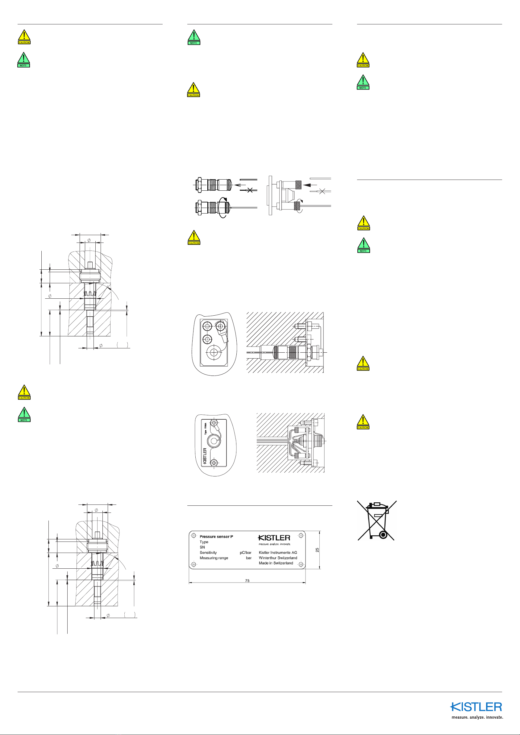
7. Installing Identification Plate
Rivet plate to side of mold or fit with four M2.5 screws.
Installation of Multichannel Connector
Example: Type 1708
5.2 Installing Contact Element in Holding Plate
Pull the cable through the mounting bore and encase it with
a silicone and fluoropolymer hose on the side of the contact
element. Push crimp contact into the contact element and
fasten on holding plate with installation nipple.
• Do not strip cable
0
+0,05
5,2
adjust 10
M8x0,75
0,010
0
4
4,2
+
30°
min2 0,3
0,05
0
0,2. ..0 ,3
2,5 H7
4,5 +
0,02 ...0 ,04
0
+0,05
5,2
adjust 10
M8x0,75
0,010
0
4
4,2
+
30°
min2 0,3
0,05
0
0,2. ..0 ,3
2,5 H7
4,5 +
0,02 ...0 ,04


