Kitagawa HG-A97-212 User manual

MA0947PHG
INSTRUCTION MANUAL
model:HG‑A97‑212
KitagawaIronWorks,Co.,Ltd.
〒726−8610
77‑1,Moto‑machi,Fuchu‑shi,Hiroshima‑pref.
TEL 0847(40)0529

1

2
Table of contents
Preface
Important Safety Precautions
1.Structural drawing and Parts list
1−1.Structural drawing
1−2.Parts list
2.Specifications
3.Relationship between gripping force and rotation speed
3−1.Maximum static gripping force
3−2.Allowable maximum rotation speed
3−3.Relationship between gripping force and rotation speed
3−4.Relationship between gripping part center height, static griping force
and input force
/ Relationship between top jaw mass moment and gripping force loss
4.Forming Soft Jaw
5.Attachment of chuck
6.Usage
7.Maintenance and Inspection
7−1.Periodic Inspection
7−2.Grease lubrication
7−3.Disassembling

3
Preface
This manual provides detailed information about how to safely and correctly use the
power chuck (HG-A97-212 type) for a lathe.
Before starting to use this power chuck, read this manual carefully and always follow
the instructions and warnings in "Important Safety Precautions" and "Precautions
for Use" at beginning of the manual. Failure to follow these precautions could result in
a serious accident.
Terms and Symbols Used for Safety Messages
In this manual, precautions for handling that are considered especially important are
classified and displayed as shown below depending on the damage of risk including the
seriousness of the harm that could result. Please sufficiently understand the meanings
of these terms and follow the instructions for safe operation.
Safety Alert Symbol
The triangle is the safety alert symbol used to alert you to potential safety hazards that
could result in injury or death.
Indicates a hazardous situation which, if yo
u not
avoided, will result in death or serious injury.
Indicates a hazardous situation which, if you not
avoided, could result in death or serious injury.
Indicates a hazardous situation which, if you not
avoided, could result in minor or moderate injury.
Indicates instructions which, if not avoided, could
result in damage to the equipment or a shortened work
life.

4
Liability and How to Use this Manual
This product is suitable for gripping a workpiece on the lathes or rotary tables. This
product is equipped with the jaws to clamp the workpiece and they operate by means of
a rotary cylinder. For any other applications, please contact us.
Our company will not assume responsibility for injury, death, damage, or loss resulting
from not following the instructions in this manual.
There are countless things that cannot or should not be done, and it is impossible to
cover all of them in this manual.
Therefore, do not perform any actions unless they are specifically allowed in this
manual. If any questions related to safety arise about operation, control, inspection and
maintenance which are not specified in this manual, please confirm them with our
company or distributor before performing them.
Guarantee and Limitation of Liability
The guarantee period of this product is 1 year after delivery.
Use the parts delivered by Kitagawa Iron Works for all the parts including consumable
parts. We will not assume responsibility for injury, death, damage, or loss caused by
usage of parts not manufactured by Kitagawa Iron Works. Additionally, if parts other than
genuine parts manufactured by Kitagawa Iron Works are used, this guarantee will be
completely invalid.
The chuck and cylinder from Kitagawa Iron Works should be used together. If you must
use a part not made by Kitagawa, check with us or our distributor to be sure it is safe to
do so. We will not be responsible for injury, death, damage or loss caused by use of a
chuck or cylinder made by another company unless this use has been approved by
Kitagawa or its distributor.

5
ImportantSafetyPrecautions
Important safety precautions are summarized below. Please read this section before
first starting to use this product.
DANGER
Failure to follow the safety precautions below will result in
serious injury or death.
Turn off main power supply before attaching, inspecting or replacing
chuck, and before adding oil.
・The chuck may start rotation suddenly, and a part of the body or clothing may be caught.
Close door before rotating spindle.
・If the door is not closed, you may touch the rotating chuck or the work may fly out, which
is very dangerous. (In general, the safety interlock function which allows rotation only
when the door is the manual mode or the test mode)
During spindle rotation, do not turn off hydraulic pump power supply and
do not operate switching valve.
・Cutting off hydraulic pressure causes a drop in the gripping force which could result in
the work being released and flying out.
・Operating the manual switching valve or solenoid valve will lead to a drop of hydraulic
pressure.
Do not allow the rotation speed of the chuck to exceed the maximum
allowable speed limit.
・The rotation speed of the chuck exceeds the rotation speed limit, this is very dangerous
as the chuck and work will fly out.
!
For All Users
For All Users
For All Users
For All Users

6
The input force of the chuck (piston thrust, pulling force of the draw pipe)
must not exceed the allowable maximum input force.
・Input must match the specification of the chuck.
・Adjust the hydraulic pressure to the cylinder so that the input force, which determines
the gripping force of the chuck, does not exceed.
・Excessive input force can lead to breakage of the chuck, which is very dangerous, as
the chuck can work can be damaged and fly out.
When gripping a work with the chuck, do not get fingers or hands become
caught.
・This could cause crushed or cut fingers and hands.
When the protrusion of the work is long, support it with the steady rest or
center.
・If the protrusion is long, the tip of the work can turn and the work fly out.
Determine the gripping force required for processing by the machine tool
manufacturer or user, and check that the required gripping force is
provided before processing.
・Adjust the hydraulic pressure to the cylinder to obtain the required gripping force. If the
gripping force is insufficient, this is dangerous as the work will fly out.
For All Users
For All Users
For All Users
For All Users

7
Use of a chuck and cylinder that cannot be used together safely may
cause the cylinder to break at high pressure resulting in the chuck and
work flying out.
・Check that the chuck and the cylinder are in the “safe combination”when using at high
pressure with our company or the distributor. Especially when the cylinder of our
company and a high pressure chuck of other company are combined, confirmation is
necessary.
・If one of the abnormal events shown below occurs during operation, immediately stop
the machine and consult with our company or the distributor.
・The work slips.
・Loss of accuracy.
・The work begins to chatter.
・The machine's vibration significantly increases.
・The griping force does not rise even if hydraulic pressure is raised.
In the case of processing a significant unbalanced work, lower the
rotation speed.
・Unbalanced work generates dangerous centrifugal forces and the work could fly out.
That grip a work in the center of the stroke.
・When gripping near the stroke end, the work may not be gripped sometimes according
to the deviation, etc., of the gripping part allowance of the work, and this is dangerous
as the work will fly out.
For All Users
For All Users
For All Users

8
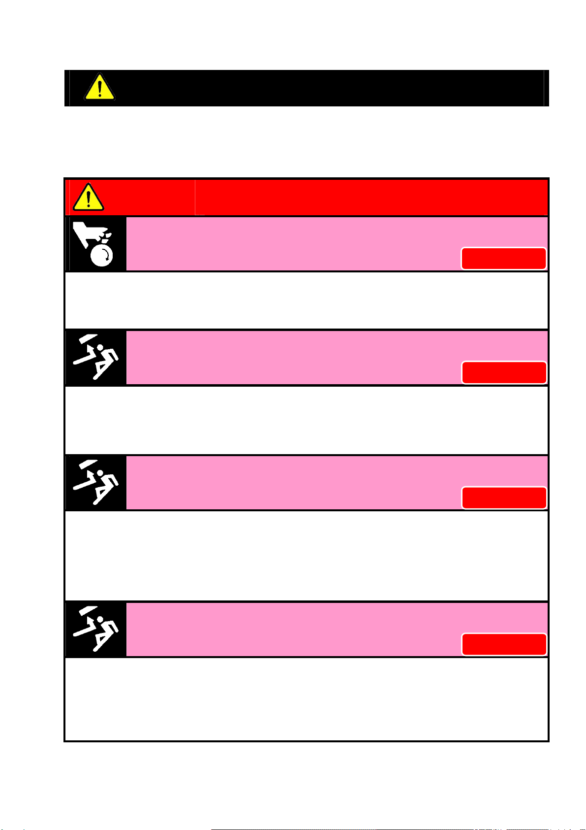
Always tighten the bolts at the specified torque. If the torque is
insufficient or excessive, the bolt will break, which is dangerous as the
chuck or work will fly out. Use the bolts attached to the chuck, and do not
use bolts other than these.
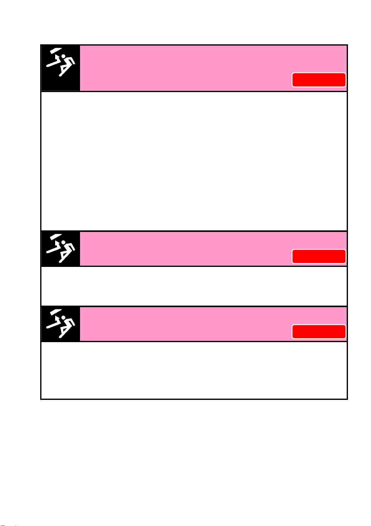
・If the torque is insufficient or
excessive, the bolt will break, which
is dangerous as the chuck or work
will fly out.
・Fix the lathe spindle or the chuck
when you tighten bolts. Your hand
could slip and get injury when you
work without fixing the spindle.
・You cannot control the torque by a
hex key. You must use a torque
wrench for torque control.
・Tighteningtorqueismomentofforcewhenyoutightenabolt.Tighteningtorque=F×L.
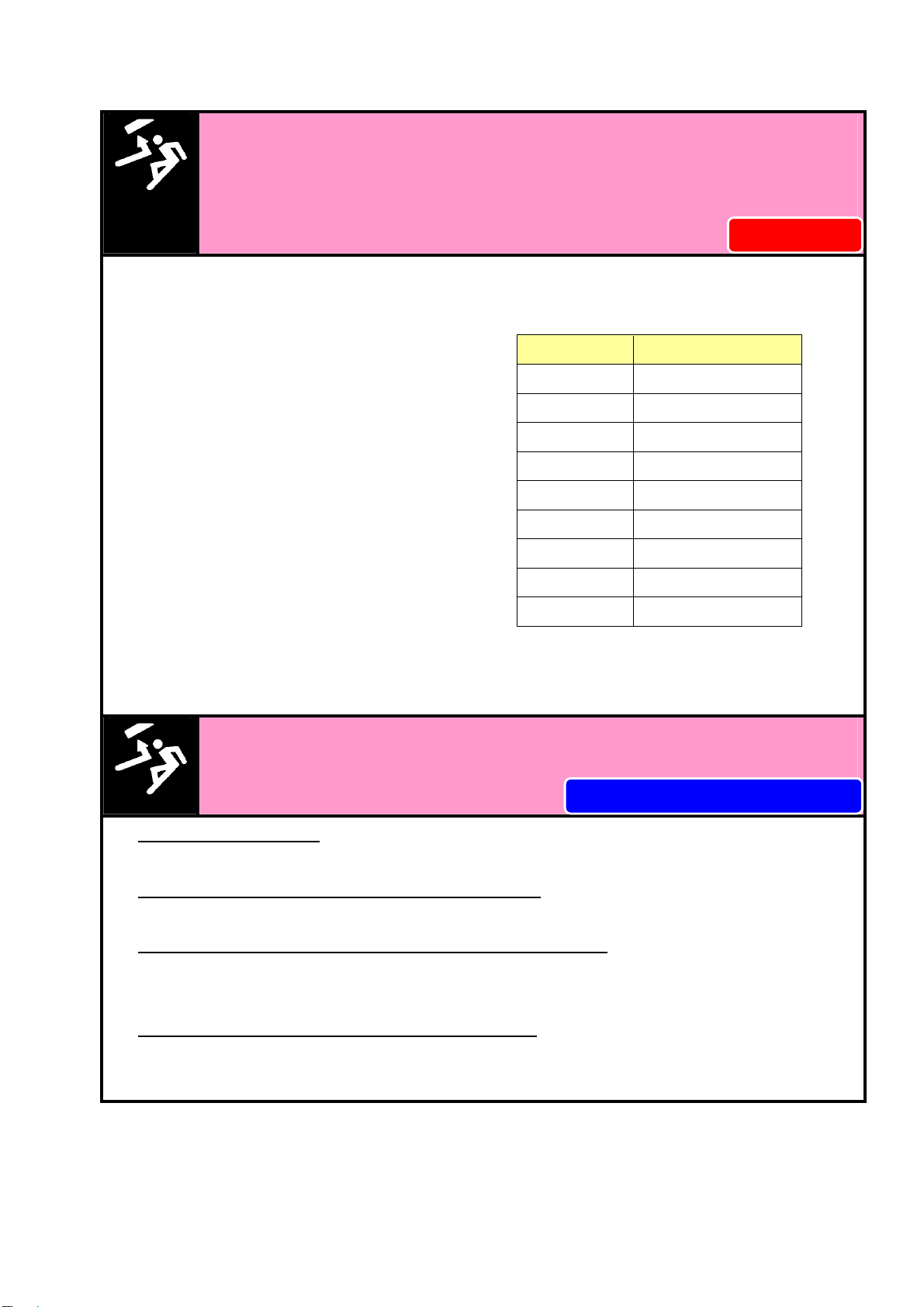
Provide sufficient strength for the draw pipe.
Provide sufficient screw depth for the draw pipe.
Firmly tighten the draw pipe.
・If the draw pipe break, the gripping force is instantly lost and this is dangerous as work
will fly out.
・If the screw depth of the draw pipe is insufficient, the screw will break and the gripping
force will be lost instantly, and this is dangerous as work will fly out.
・If the engagement of the screw of the draw pipe is loose, vibration may occur resulting
in breakage of the screw. If the screw breaks, the gripping force will be lost instantly,
which is dangerous as the work will fly out.
・If the draw pipe is unbalanced, vibration occurs, the screw is broken and the gripping
force will be lost instantly, which is dangerous as the work will fly out.
Specified torque for
socket head cap screw
Bolt size Tightening torque
M4 3.8 N・m
M5 7.5 N・m
M6 13 N・m
M8 33 N・m
M10 73 N・m
M12 107 N・m
M14 171 N・m
M16 250 N・m
M20 402 N・m
For Machine Tool Manufactures
For All Users

9
Use a cylinder with a lock valve (safety valve, check valve) incorporated in
case of sudden hydraulic pressure drop due to blackout, malfunction of
the hydraulic pump, etc. Further, use a solenoid valve with a circuit that
retains the gripping position when no current is carried.
・If the hydraulic pressure suddenly drops due to blackout or malfunction of the hydraulic
pump, etc., this is dangerous as work will fly out.
・Lock valve retains the hydraulic pressure inside the cylinder temporarily, when the
hydraulic pressure suddenly drops due to blackout or malfunction of the hydraulic pump,
etc.
ImportantSafetyPrecautions
WARNING
Failure to follow the safety precautions below could result in
serious injury or death.
Do not modify the chuck in a way not permitted by the manufacturer.
・It may not only break the chuck but the chuckand the work may fly out, which is
dangerous.
・If you attach a locator or jig on the chuck body surface, only process work in an
acceptable range
Periodically supply adequate grease. Turn off power before adding
grease.
・Insufficient grease supply lowers the gripping force, causes operation failure due to
lower hydraulic pressure, lowers the gripping precision, and causes abnormal wearing
and seizing, etc.
・This is dangerous as the work could fly out from a drop in the gripping force.
For Machine Tool Manufactures
!
For All Users
For All Users

10
Do not operate the machine
after drinking alcohol or taking
medication.
Do not operate the machine wearing
gloves, a necktie, and other loose
clothing or
jewelry.
・Dangerous since these lead to operation
mistakes and misjudgment. ・Dangerous since it will be caught.
Do not grip a chuck with a chuck.
・Because it is easy to confuse the specifications of each chuck and the protrusion
become long and is apt to raise rotation speed, it is apt to exceed the specifications of
the base chuck. The chuck may break and the chuck or work could fly out.
For All Users For All Users
For All Users

11
1.StructuraldrawingandPartslist
1−1.Structuraldrawing
Fig.1

12
1−2.Partslist
Table1
No. Partname Quantity
A
Body 1 04
Socketheadcapscrew M4×8 5
B
Masterjaw 5 05
Socketheadcapbuttonscrew M6×12 5
C
Softjaw 5 06
Setscrewhalfdogpoint M6×16
5
D
Spacer 10 07
SetscrewflatpointM8×8 5
E
Lever 5 08
SetscrewflatpointM20×16 5
F
Leverpin 5 09
Greasenipple A M6 5
G
Plunger 1 10
spring (blue) 5
H
Cover A 1 11
spring (yellow) 10
J
Cover B 1 12
Parallelpinφ6×18 5
01
Socketheadcapscrew M10×40
5 13
Setscrewflatpoint M8×8 10
02
Socketheadcapscrew M10×25
10
03
Socketheadcapscrew M4×12 5
2.Specifications Table2

13
3.Relationshipbetweengrippingforceandrotationspeed
3−1.Maximumstaticgrippingforce
The static gripping force is the gripping force when the chuck is at a stop.
The power chuck has a mechanism to convert input force (piston thrust force, draw pipe
drawing force) from the cylinder to gripping force. Therefore, the gripping force when the
allowable maximum input force becomes the maximum static gripping force.
However, the gripping force is different depending on the state of grease lubrication,
grease in use, height of the jaw, etc. The maximum static gripping force specified in the
specification is the value under the following conditions:
・The Kitagawa standard soft jaw is used as the jaw.
・The attaching bolts of the soft jaw are tightened at the specified torque.
・The numerical values are obtained with the Kitagawa gripping force meter . The
gripping position of the gripping force meter is at a position the chuck surface.
・CHUCK GREASE PRO is used.
・Avariable displacement pump with the discharge volume of 20 liters/min or more is
used as the hydraulic source. The pressure is set by the pressure control equipment
of the pump itself, or the pressure reduction valve equipped separately.
3−2.Allowablemaximumrotationspeed
In the case of outside diameter gripping, when the chuck is rotated, the gripping force
lowers due to the centrifugal force of the top jaw. The centrifugal force is different
depending on the mass of the top jaw and the barycentric position as well as the
rotation speed. The allowable maximum rotation speed specified in the specification is
the value under the following conditions:
・The Kitagawa standard soft jaw is used.
・Grip the gripping force meter in the center of the jaw stroke.
・The gripping position of the gripping force meter is at a position the chuck
surface(Theoretical value).

14
To avoid serious accidents caused by the chuck or work flying out:
・Determine the gripping force required for processing by the machine tool
manufacturer or user, and check that the required gripping force is
provided before processing. The gripping force of the chuck must not
exceed the maximum static gripping force.
・Determine the rotation speed required for processing by the machine tool
manufacturer or user based on the gripping force required for the
processing. The rotation speed at this point must not exceed the allowable
maximum rotation speed.

15
3−3.Relationshipbetweengrippingforceandrotationspeed
As the rotation speed becomes higher, the centrifugal force of the jaw increases and the
gripping force lowers. The curves displayed in Fig. 2 shows relationships between the
rotation speed and the centrifugal force when using the standard soft jaw. The
centrifugal force differs significantly depending on the size and shape of the top jaw and
the attaching position, therefore, when the rotation speed is high, actual measurement
using a Kitagawa gripping force meter is required.
Fig.2
・In the case of processing a considerably unbalanced work, lower the
rotation speed. The work will fly out and this is dangerous.
・Vibration is generated if there is unbalance due to the work and the jig, etc.
Vibration decreases process precision and shortens the working life of the
chuck, even possibly breaking it.Correct the unbalance by using a balance
weight, etc., or lower the rotation speed for use.
・In the case of heavy cutting at high rotation speed, vibration is easily
generated in the same manner as the unbalance of the chuck, therefore, set
the cutting conditions appropriate for the dynamic gripping force and
machine rigidity.

16
3−4.Relationshipbetweengrippingpartcenterheight,staticgriping
forceandinputforce/Relationshipbetweentopjawmassmoment
andgrippingforceloss
If the gripping part center height of the used top jaw is higher than the chuck surface, a
large load is applied to the master jaw, rever, jaw attaching bolts, etc. To prevent these
parts from being broken, it is necessary to use the machine by using a lower input force
than the allowable maximum input force.
Additionally, if the top jaw is larger and heavier, the centrifugal force generated at the
top jaw will increase. It is necessary to examine the dynamic gripping force considering
the centrifugal force and to use the machine at a rotation speed that can withstand the
cutting force.
Fig.3
・Keep the height of the top jaw within the range of the gripping force limit
table. (Refer to Fig.3)
・If the gripping part center height of the used top jaw is higher than the
chuck surface, use it at the input force (piston thrust force, draw pipe
drawing force) specified in the gripping force limit table. If it is used without
lowering the input, the chuck will break and this is dangerous as the chuck
and work will fly out.

17
4.Formingsoftjawwithoutsidediametergripping
1.Preparation of the ring for forming
・Prepare the ring for forming. The surface roughness
of the ring inside diameter and part to locate in jaw
front surface are to be approximately 25s, and make
a shape with a sufficient thickness which does not
distort.
・Recommended gripping dia. φd=φ119、 a=6
2 . Process of the ring gripping part for
forming
・Operate the switch valve and maximize the opening
of the jaw.
・Then, process the φD part (part to grip the ring for
forming). Set the dimension φD so that gripping
near the center of the jaw maximum stroke
(diameter) is possible.
・φD = φd + (jaw maximum stroke/2)
3.Gripping of the ring for forming
・By operating the switch valve, grip the ring for
forming in the φD part. At this time, grip by
pressing the ring on the jaw front surface in order for
the ring not to be tilted. Repeat chucking several
times to stabilize the ring.
・Set the hydraulic pressure during forming the same
as during processing of the work, or slightly higher.
・When the ring distorts, lower the hydraulic pressure
or change the ring into a shape which does not
easily distort.

18
4.Adjustment of gripping part center height
・When gripping a work, cut down the c-section
gripping center so that the surface of the chuck.
If using standard soft jaw, the b-section
dimensions will be 14mm.
Processed to while holding the ring.
5.Forming
・Process the gripping part (dimension φD’) of the
work in the state that the ring is kept gripped. The
φD’part is to be approximately the same diameter
(H7) as the diameter of the gripping part of the work,
and process to be surface roughness at 6s or less.
6.Trial cutting
・Remove the ring for forming and grip the work to
check the jaw stroke.
・Implement trial cutting to check the process
precision and that there is no slip, etc.

19
5.Attachment of chuck
・Turn off the main power of the machine before starting work.
・Read the following disassembling procedures with reference to page 11,12.
・Always tighten the bolts at the specified torque.
①Attach the cylinder and draw-pipe to the spindle. Move 2 to 3 times at low pressure
(0.4 MPa) and set the piston at the forward end and turn off the power supply.
②If the fixture is attached to the chuck, please remove in advance.
③Use an eyebolt when attaching the chuck to the machine. Screw the draw pipe to
the plunger [G] by turning the spindle.
④If it is set to 0.5mm between the draw pipe and plunger, loosen the draw pipe and
back 1/4 turn from the spindle position is screwed. Please fix chuck to spindle with
socket head cap screws(M10×40)[01] then.It can be a gap of 0.5mm between the
plunger[G] and draw pipe, as shown in FIG 4. Amount to rotate the spindle from the
position screwed by gaps that set will change.
If it is set to 1.0mm between the draw pipe and plunger, loosen the draw pipe and
back 1/2 turn from the spindle position is screwed.
If it is set to 1.5mm between the draw pipe and plunger, loosen the draw pipe and
back 3/4 turn from the spindle position is screwed.
⑤To make sure that it is allowed to stroke the cylinder, jaw stroke of the provisions
have been obtained.
⑥If jaw stroke is short, loosen the socket head cap screws(M10×40)[01],loosen the
screw by 1/5 rotation of the spindle, fix chuck to spindle with socket head cap
screws(M10×40). Please check the jaw stroke then.
Jaw stroke will increase by 0.3mm to loosen the screw by 1/5 rotation of the spindle.
Please note Jaw stroke to be no larger than 1.5mm.
Fig.4
Table of contents
Other Kitagawa Power Tools Accessories manuals