EnglishDeutsch
 logo
Brands
  1. Home
  2. •
  3. Brands
  4. •
  5. KitchenAid
  6. •
  7. Ventilation Hood
  8. •
  9. KitchenAid KXW4430Y User manual

KitchenAid KXW4430Y User manual

This manual suits for next models

1

Other KitchenAid Ventilation Hood manuals

KitchenAid KHTU105LSS0 User manual

KitchenAid

KitchenAid KHTU105LSS0 User manual

KitchenAid KHTU160KBT1 Product information sheet

KitchenAid

KitchenAid KHTU160KBT1 Product information sheet

KitchenAid KVWC958JSS Product information sheet

KitchenAid

KitchenAid KVWC958JSS Product information sheet

KitchenAid KICU285HAL0 User manual

KitchenAid

KitchenAid KICU285HAL0 User manual

KitchenAid Pro-Line KICV167RMT0 Product information sheet

KitchenAid

KitchenAid Pro-Line KICV167RMT0 Product information sheet

KitchenAid KWCU405S Parts list manual

KitchenAid

KitchenAid KWCU405S Parts list manual

KitchenAid ISLAND CANOPY Product information sheet

KitchenAid

KitchenAid ISLAND CANOPY Product information sheet

KitchenAid KIRD862VSS Product information sheet

KitchenAid

KitchenAid KIRD862VSS Product information sheet

KitchenAid W10268947B Product information sheet

KitchenAid

KitchenAid W10268947B Product information sheet

KitchenAid KWCU265HBT0 User manual

KitchenAid

KitchenAid KWCU265HBT0 User manual

KitchenAid KHLU182MSS1 User manual

KitchenAid

KitchenAid KHLU182MSS1 User manual

KitchenAid KXI4336YSS Product information sheet

KitchenAid

KitchenAid KXI4336YSS Product information sheet

KitchenAid KVWC956KSS User manual

KitchenAid

KitchenAid KVWC956KSS User manual

KitchenAid YKMHP519 User manual

KitchenAid

KitchenAid YKMHP519 User manual

KitchenAid 36" Product information sheet

KitchenAid

KitchenAid 36" Product information sheet

KitchenAid KIRD801XSS3 User manual

KitchenAid

KitchenAid KIRD801XSS3 User manual

KitchenAid KHTU705 User manual

KitchenAid

KitchenAid KHTU705 User manual

KitchenAid 42 Manual

KitchenAid

KitchenAid 42 Manual

KitchenAid W10268948C Product information sheet

KitchenAid

KitchenAid W10268948C Product information sheet

KitchenAid KHTU105RSS1 Instructions for use

KitchenAid

KitchenAid KHTU105RSS1 Instructions for use

KitchenAid KitchenAid KVUC600KSS0 Manual

KitchenAid

KitchenAid KitchenAid KVUC600KSS0 Manual

KitchenAid UXG7480VDS0 User manual

KitchenAid

KitchenAid UXG7480VDS0 User manual

KitchenAid KHMS105W User manual

KitchenAid

KitchenAid KHMS105W User manual

KitchenAid KHVU761RSS1 User manual

KitchenAid

KitchenAid KHVU761RSS1 User manual

Popular Ventilation Hood manuals by other brands

Haier CXW-219-D67 null

Haier

Haier CXW-219-D67 null

emmeti RECUPA MED A-140 Installation and use manual

emmeti

emmeti RECUPA MED A-140 Installation and use manual

Nibe F135 user manual

Nibe

Nibe F135 user manual

Zephyr Spruce AK9834BS Use, care and installation guide

Zephyr

Zephyr Spruce AK9834BS Use, care and installation guide

Kuppersberg INTRO 60 Technical Passport

Kuppersberg

Kuppersberg INTRO 60 Technical Passport

Hisense MH6INBG manual

Hisense

Hisense MH6INBG manual

Miele DA 1255 Operating and installation instructions

Miele

Miele DA 1255 Operating and installation instructions

Broan 46000 Specification sheet

Broan

Broan 46000 Specification sheet

GE Profile PV977 Owner's Manual & Installation Instructions

GE

GE Profile PV977 Owner's Manual & Installation Instructions

FALMEC FFRIA24W5FS Instruction booklet

FALMEC

FALMEC FFRIA24W5FS Instruction booklet

Whirlpool RH2600XL-1 SERIES installation instructions

Whirlpool

Whirlpool RH2600XL-1 SERIES installation instructions

ETNA AV360RVS Instructions for use

ETNA

ETNA AV360RVS Instructions for use

JUNO JDF603E6 installation manual

JUNO

JUNO JDF603E6 installation manual

Miele DA 6708 D Operating and installation instructions

Miele

Miele DA 6708 D Operating and installation instructions

Tricity Bendix LE 150 Installation & operating instructions

Tricity Bendix

Tricity Bendix LE 150 Installation & operating instructions

AEG X68163BV1 user manual

AEG

AEG X68163BV1 user manual

AEG 125 D operating instructions

AEG

AEG 125 D operating instructions

Smeg KSEV97X instruction manual

Smeg

Smeg KSEV97X instruction manual

https://manuals.online logo
https://manuals.online logoBrands
  • About & Mission
  • Contact us
  • Privacy Policy
  • Terms and Conditions

Copyright 2026 Manuals.Online. All Rights Reserved.

10" (25.4 cm) min.
13" (33.0 cm) max.
9¹⁄₂" (24.1 cm)
2" (5.1 cm) min.
9" (22.9 cm) min.*
Centerline
Side
cabinet Side
cabinet
Vent and power
supply cable
entry location
17" (43.2 cm)*
30" (76.2 cm) or
36" (91.4 cm)
"X"
bottom of
canopy
to cooking
surface
10" (25.4 cm) min.
13" (33.0 cm) max.
Cooking surface
30" (76.2 cm) and 36" (91.4 cm) Wall-Mount Canopy Range Hood
PRODUCT MODEL NUMBERS
KXW4430Y KXW4436Y
Because Whirlpool Corporation policy includes a continuous commitment to improve
our products, we reserve the right to change materials and specifications without notice. Dimensions are for planning purposes only. For complete details, see Installation
Instructions packed with product. Specifications subject to change without notice. Ref. W10322990E
2/8/2012
CABINET OPENING DIMENSIONS
Electrical Requirements:
● A 120 volt, 60 Hz., AC only, 15-amp, fused electrical circuit is
required.
● If the house has aluminum wiring, follow the procedure below:
1. Connect a section of solid copper wire to the pigtail
leads.
2. Connect the aluminum wiring to the added section
of copper wire using special connectors and/or
tools designed and UL listed for joining copper to
aluminum.
Follow the electrical connector manufacturer's recommended
procedure. Aluminum/copper connection must conform with local
codes and industry accepted wiring practices.
*For non-vented (recirculating) installations
IMPORTANT:
Minimum distance “X”: 24" (61.0 cm) from electric
cooking surface.
Minimum distance “X”: 27" (68.6 cm) from gas
cooking surfaces.
Suggested maximum distance “X”: 36" (91.4 cm)
The chimneys can be adjusted for different ceiling heights. See the
following chart.
Vented Installations
Min. ceiling height Max. ceiling height
Electric cooking surface 7' 5" (2.26 m) 9' 6" (2.9 m)
Gas cooking surface 7' 8" (2.34 m) 9' 6" (2.9 m)
Non-vented (recirculating) Installations
Min. ceiling height Max. ceiling height
Electric cooking surface 7' 5" (2.26 m) 9' 10" (3.0 m)
Gas cooking surface 7' 8" (2.34 m) 9' 10" (3.0 m)
NOTE: The range hood chimneys are adjustable and designed to
meet varying ceiling or soffit heights depending on the distance “X”
between the bottom of the range hood and the cooking surface. For
higher ceilings, a Stainless Steel Chimney Extension Kit Part Number
W10272076 is available from your dealer or an authorized parts
distributor. The chimney extension replaces the upper chimney
shipped with the range hood.
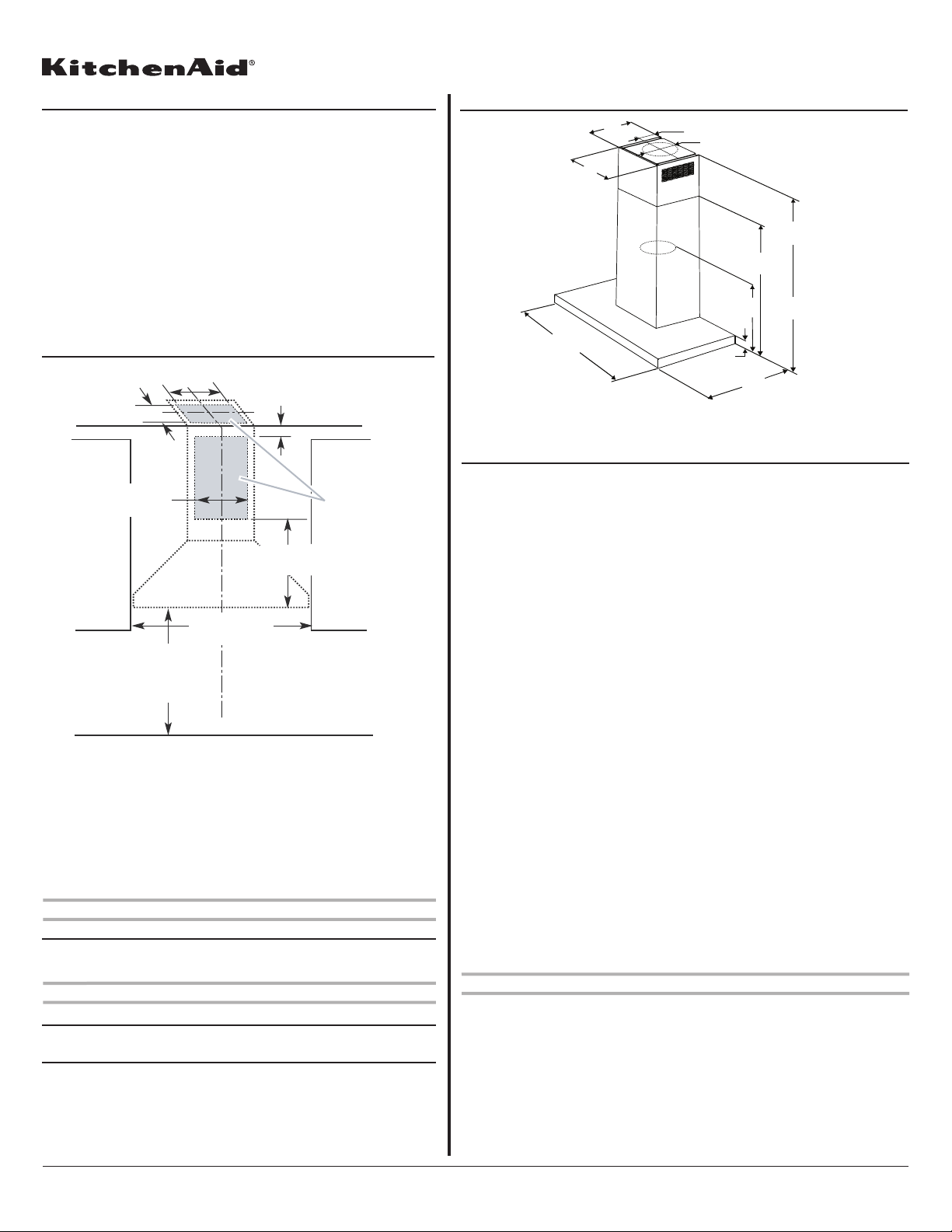
PRODUCT DIMENSIONS
*For non-vented (recirculating) installations
**For vented installations
10⁵⁄₈" (26.9 cm)
13¹⁄₁₆" (33.2 cm)
4⁷⁄₈" (12.3 cm)
5⁷⁄₈" (15.0 cm)
*29" (73.7 cm) min.
46⁹⁄₁₆" (118.3 cm) max.
**29" (73.7 cm) min.
42¾" (108.6 cm) max.
19¹⁄₁₆"
(48.5 cm)
15 ¹⁄₄"
(38.7 cm)
2³⁄₈"
(6.0 cm)
19¹¹⁄₁₆" (50.0 cm)
30" (76.2 cm)
36" (91.4 cm)
VENTING REQUIREMENTS
● Vent system must terminate to the outdoors, except for non-vented
(recirculating) installations.
● Do not terminate the vent system in an attic or other enclosed area.
● Do not use 4" (10.2 cm) laundry-type wall cap.
● Use metal vent only. Rigid metal vent is recommended. Plastic or metal foil
vent is not recommended.
● The length of vent system and number of elbows should be kept to a
minimum to provide efficient performance.
For the most efficient and quiet operation:
● Use no more than three 90° elbows.
● Make sure there is a minimum of 24" (61.0 cm) of straight vent between the
elbows if more than 1 elbow is used.
● Do not install 2 elbows together.
● Use clamps to seal all joints in the vent system.
● The vent system must have a damper. If the roof or wall cap has a damper, do
not use the damper supplied with the range hood.
● Use caulking to seal exterior wall or roof opening around the cap.
● The size of the vent should be uniform.
Cold Weather Installations
An additional back draft damper should be installed to minimize backward cold
air flow and a thermal break should be installed to minimize conduction of
outside temperatures as part of the vent system. The damper should be on the
cold air side of the thermal break.
The break should be as close as possible to where the vent system enters the
heated portion of the house.
Makeup Air
Local building codes may require the use of makeup air systems when using
ventilation systems greater than specified CFM of air movement. The specified
CFM varies from locale to locale. Consult your HVAC professional for specific
requirements in your area.
Venting Methods
This canopy hood is factory set for venting through the roof or wall.
A 6" (15.2 cm) round vent system is needed for installation (not included). The
hood exhaust opening is 6" (15.2 cm) round.
NOTE: Flexible vent is not recommended. Flexible vent creates back pressure
and air turbulence that greatly reduce performance.
Vent system can terminate either through the roof or wall. To vent through a
wall, a 90° elbow is needed.
Rear discharge
A 90° elbow may be installed immediately above the hood. Page 1 of 2
Because Whirlpool Corporation policy includes a continuous commitment to improve
our products, we reserve the right to change materials and specifications without notice. Dimensions are for planning purposes only. For complete details, see Installation
Instructions packed with product. Specifications subject to change without notice. Ref. W10322990E
2/8/2012
Page 2 of 2
Calculating Vent System Length
To calculate the length of the system you need, add the equivalent feet
(meters) for each vent piece used in the system.
Vent Piece 6" (15.2 cm) Round
45°elbow 2.5 ft
(0.8 m)
90°elbow 5.0 ft
(1.5 m)
Maximum equivalent vent length is 35 ft (10.7 m).
For Non-Vented (recirculating) Installations
If it is not possible to vent cooking fumes and vapors to the outside, the
hood can be used in the non-vented (recirculating) version, using a
Recirculation Kit (which includes charcoal filters and a deflector). To
order, see the “Assistance or Service”section.
Roof Venting Wall Venting Non-vented
(recirculating)
A. Roof cap
B. 6" (15.2 cm)
round vent
A. Wall cap
B. 6" (15.2 cm)
round vent
A. Deflector
B. 6" (15.2 cm)
round vent
The following example falls within the maximum recommended vent
length of 35 ft (10.7 m).
1 - 90°elbow = 5.0 ft (1.5 m)
1 - wall cap = 0.0 ft (0.0 m)
8 ft (2.4 m) straight = 8.0 ft (2.4 m)
Length of system = 13.0 ft (3.9 m)
Example vent system
90 elbow 6 ft (1.8 m)
2 ft
(0.6 m)
Wall cap