KLAU Geomatics M200 User manual

Table of Contents
Table of Contents..................................................................................................................................2
Disclaimer.............................................................................................................................................2
Hardware Overview..............................................................................................................................4
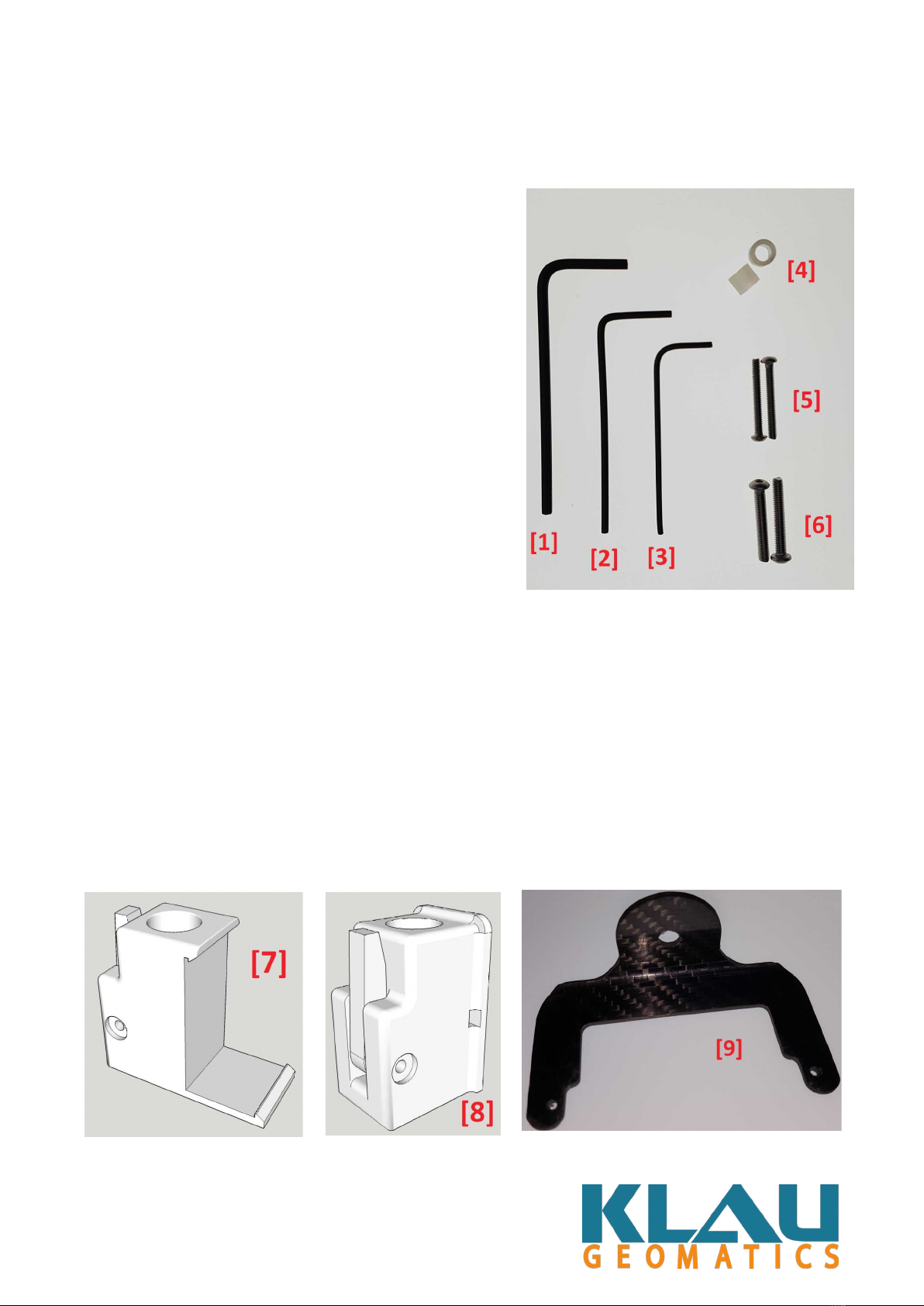
Antenna Bracket ounting Kit........................................................................................................4
Other Hardware................................................................................................................................4
Installation............................................................................................................................................5
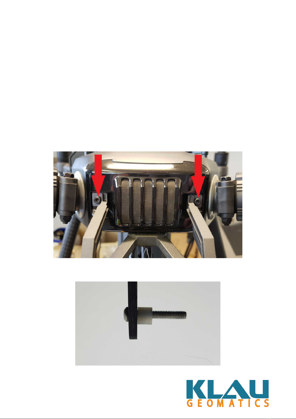
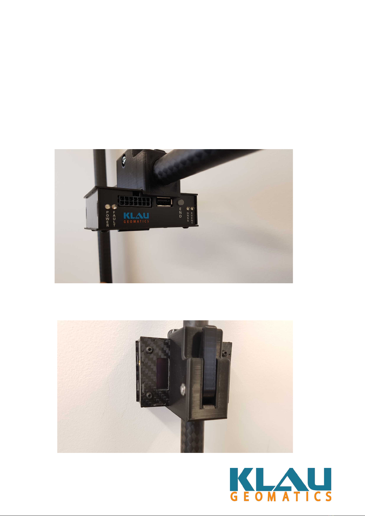
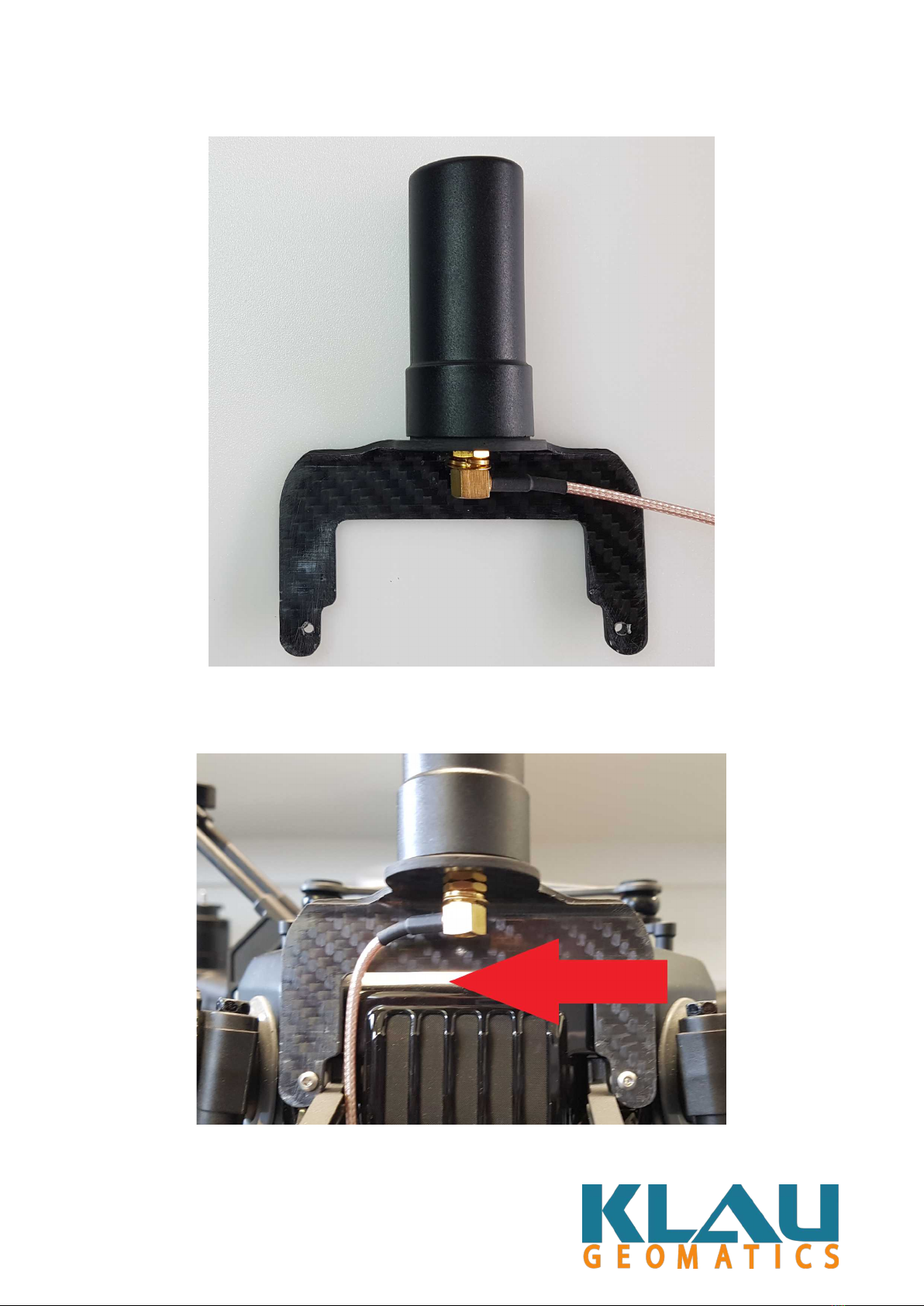
Antenna Bracket..............................................................................................................................5
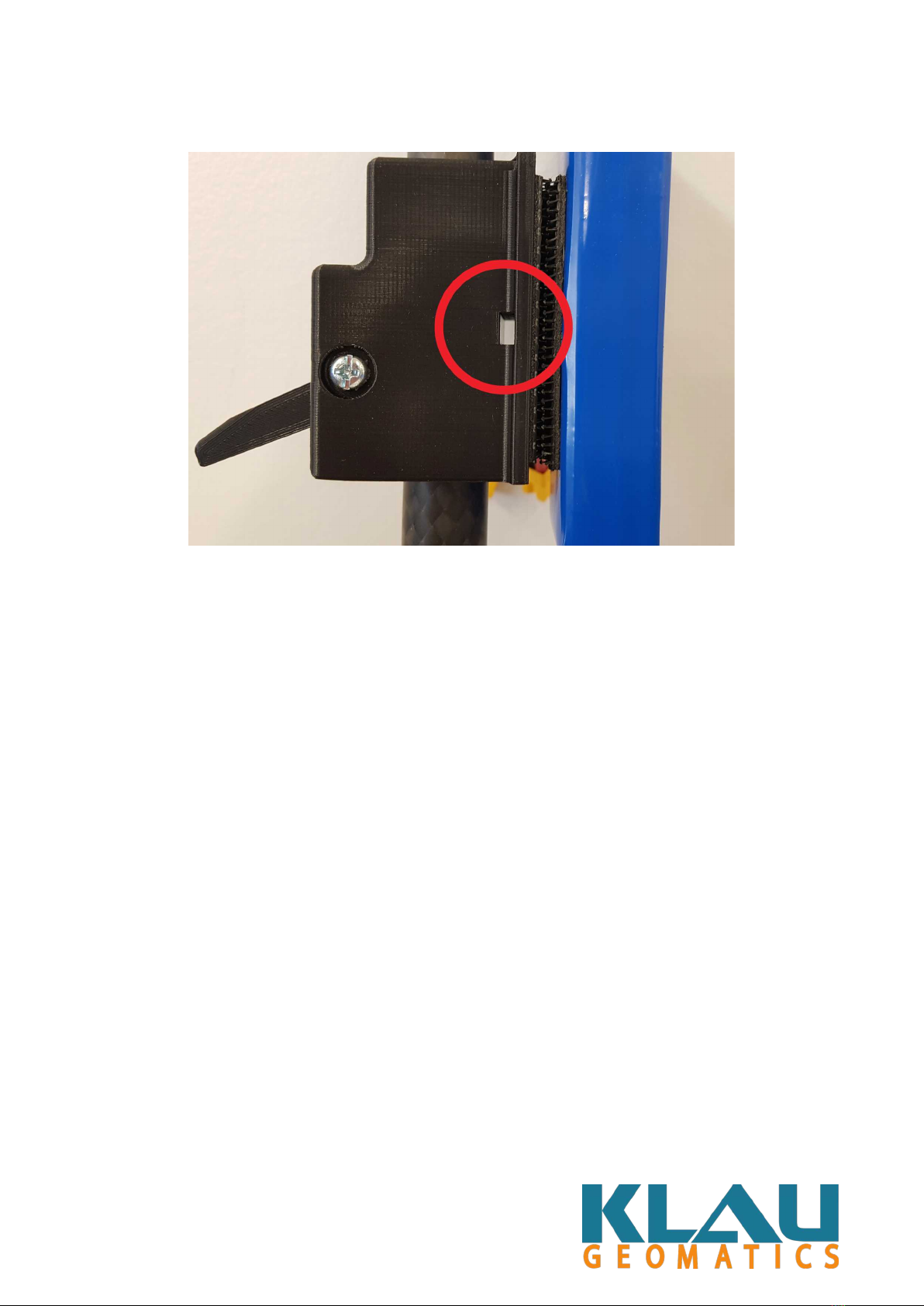
Battery..............................................................................................................................................9
PPK & PPP....................................................................................................................................11
Antenna & Antenna Cable.............................................................................................................12
Klau Gimbal...................................................................................................................................18
Electrical Connections........................................................................................................................21
Wire Harness Overview.................................................................................................................21
Wire Harness Overview Cont........................................................................................................22
Connections required for use with DJI Camera.............................................................................23
Connections required for use with Klau Gimbal...........................................................................24
Disclaimer
!
" #$%
Rev0
2

Har ware Overview
Antenna Bracket Mounting Kit
1. Allen Key 2mm (x1)
2. Allen Key 1.5mm (x1)
3. Allen Key 1.25mm (x1)
4. Nylon Spacer – 3 4mm (x2)
5. Bolt – 2 16mm (x2)
6. Bolt – 2.5 16mm (x2)
Note: We have intentionally included both
M2 & M2.5 bolts as DJI have used
different sizes depending on model batch.
Please use the size that fits your drone.
Other Har ware
7. PPK/PPP Cam-Lock ount
8. Battery Cam-Lock ount
9. Antenna Bracket
Rev0
3

Installation
Antenna Bracket
•Using the appropriate supplied Allen Key, remove the 2x upper gimbal support bolts
[Figure 1]
•Prepare the bracket for installation using the appropriate bolts to fit your model of drone
[Figure 2 & 3] this will assist in mounting the bracket with ease.
•Use the appropriate Allen Key to tighten the new bolts into the existing mount holes. Ensure
these bolts are tight before proceeding. [Figure 4]
Figure 1:
Figure 2:
Rev0
4

Figure 3:
Figure 4:
Rev0
5

Battery
•The Klau Cam-Lock mounts should be installed before the drone’s legs are attached. The
mounts are slid down from the top of the leg piece. [Figure 1] Please take note of the
orientation of the mount when attaching to leg. When looking at the front of the drone, the
battery is on the Left-hand leg.
•To clamp the mount into place, simply close the lever. [Figure 2 & 3]
•Dual Lock is provided to attach your Lipo battery pack to the Cam-Lock mount. A cable tie
can also be used for added security. A hole for a cable tie or other form of mechanical hold
has been provided. [Figure 4]
Figure 1:
Figure 2 & 3:
Rev0
6

Figure 4:
Rev0
7

PPK & PPP
•The Klau Cam-Lock mounts should be installed before the drone’s legs are attached. Please
refer to the previous section Mounting Battery for details on installing the Cam-Lock
ount.
•The PPK or PPP unit should be mounted on the Right-side leg of the drone when looking at
it from the front.
•Once the 2nd Cam-Lock mount is installed, your PPK or PPP unit can be clipped into the
mount. Refer to images for correct orientation. [Figure 1 & 2]
Figure 1:
Figure 2:
Rev0
8

Antenna & Antenna Cable
•Place the threaded S A connector of the Antenna Cable through the hole in the mounting
bracket on its under-side as illustrated. [Figure 1] You should have roughly 5mm of thread
exposed on the top of the bracket.
•Thread your antenna onto the S A connector. The Antenna will screw down until it is
touching the carbon fibre bracket. This fitting should be firm enough not to move but not
excessively tight. [Figure 2]
•As a safety measure, please ensure your antenna cable is sitting snug against the body of
your drone where it cannot possibly be hit by the props. [Figure 3]
•Once the antenna cable is positioned correctly, and the Antenna has been tightened down
onto its bracket, connect the other end of your antenna cable to your PPP or PPK unit.
[Figure 4]
Figure 1:
Rev0
9

Figure 2:
Figure 3:
Rev0
10

Figure 4:
Rev0
11

Klau Gimbal
•The Klau Gimbal mounts to your drone in the same way as DJI cameras and gimbals
[Figure 1, 2 & 3].
•Ensure the locking mechanism has clicked into place when installing your gimbal.
•For further details on your DJI Bayonet fitting, please refer to your drone’s user manual.
•For details on setting up your Klau Gimbal for the first time please refer to “Klau
Geomatics - Gimbal Manual”
Figure 1:
Rev0
12

Figure 2:
Figure 3:
Rev0
13

Electrical Connections
Wire Harness Overview
1. Klau PPK or PPP unit main 14-pin connector
2. Trigger Output to Camera – Connects to Gimbal (not required with DJI cameras)
3. Capture/Event Input from Camera – Connects to Klau Gimbal or to DJI Camera
4. Auxiliary Power Output – Connects to Gimbal (not required with DJI cameras)
5. ain Power Input – Connects to Battery (can also be connected to the 210’s Aux Power
Plug, please refer to your DJI owners manual for more information regarding this connector.
Note: The Main Power Input has 2 onne tions so that a battery swap an be performed without
turning the system off.
For more in-depth details on your PPK or PPP unit please refer to the “Klau Geomati s –
7700 Series Manual”
Rev0
14

Wire Harness Overview Cont.
•When installing any cables onto your drone it is extremely important to make sure all cables
are secured and can not interfere with props or flight sensors.
•Klau Geomatics recommends using the cable path shown below [Figure 1]. Passing cables
through the frame in this location (behind gimbal) will avoid any issues caused by loose
cables.
•For additional security, cable ties may be used to fix wiring to your drone’s frame.
Figure 1:
Rev0
15

Connections require for use with DJI Camera
•Connect the main 14-pin connector to your PPK or PPP unit – Ensure the locking tab
engages once inserted.
•Connect the Capture/Event cable to your modified DJI camera’s cable [Figure 1]
•Connect 1 of the ain Power Inputs to your battery
•If you have already connected your antenna cable, as mentioned on page 9, your system is
now ready. [Figure 2]
Figure 1:
Figure 2:
Rev0
16

Connections require for use with Klau Gimbal
•Connect the main 14-pin connector to your PPK or PPP unit – Ensure the locking tab
engages once inserted.
•Connect the Auxiliary Power Output to its mating connector on the gimbal. [Figure 1 A]
•Connect the camera input and output plugs to their mating connections on the gimbal.
[Figure 1 B]
•Connect 1 of the ain Power Inputs to your Lipo battery.
•If you have already connected your antenna cable, as mentioned on page 9, your system is
now ready. [Figure 2 & 3]
Figure 1:
Figure 2:
Rev0
17

Figure 3:
Rev0
18
This manual suits for next models
1
Table of contents
Other KLAU Geomatics Drone manuals