KLC Generation 2 User manual

VERSION 6 30/09/2020
BEVEL BACK WEATHERBOARD DIRECT FIX INSTALLATION MANUAL
NZ Timber Cladding Systems
CM70062
PROUDLY MADE IN NZ BY
NATURAL. DURABLE. CLASSIC.

2
KLC Generation 2 H3.2 Installation and Technical Guide
Generation 2 bevelback weatherboards
are proudly 100% New Zealand made.
We pride ourselves on delivering a premium
weatherboard to work with and know you are well
protected.
• Treatment warranty of 50 years protection.
• Treated with Koppers MicroPro®Wood Treatment Technology.
• Reduced corrosivity allowing the use of corrosion-resistant fasteners including hot-
dipped galvanised, stainless steel or other approved fasteners to meet building code
requirements
• New Zealand Radiata Pine sourced from renewable plantation forestry. KLC is a Chain
of Custody, FSC®Certified Company.
• Eco-friendly with four environmental credentials.
• Weatherboards up to 6.3 metres in length.
• Formaldehyde-free and low volatile organic compounds used in the treating and gluing
manufacturing process.
• No odour.
• A two coat, superior alkyd (oil based) priming system.
• Approved for aluminium contact.

3
KLC Generation 2 H3.2 Installation and Technical Guide
Table of Contents
DISCLAIMER ................................................................................................. 3
1 GENERAL INFORMATION
1.1 Scope and General Information................................................... 4
1.2 Product Information.................................................................... 4
1.3 Architects/Designers Responsibility ............................................ 6
1.4 Legal Information ....................................................................... 6
1.5 On-Site Storage and Handling - KEEP IT DRY.............................. 7
2LIFE SERVICEABILITY
2.1 Warranty .................................................................................... 8
3GUIDELINES FOR INSTALLATION
3.1 Pre-Installation Checks............................................................. 10
3.2 Framing ................................................................................... 10
3.3 Nail Selection ............................................................................11
3.4 Installation ............................................................................... 12
3.5 Joins and Pipe Penetration ....................................................... 13
3.6 Wall Underlay and Flashing Tapes............................................. 13
3.7 Windows and Door Openings .................................................... 13
3.8 Flashings.................................................................................. 14
3.9 Sealants................................................................................... 14
3.10 Air Seals .................................................................................. 14
3.11 Wall Cladding Cavities .............................................................. 14
3.12 External and Internal Corner Details.......................................... 15
3.13 External and Internal Box Corner Details ................................... 15
3.14 Windows and Doors (Aluminium) .............................................. 16
3.15 Window and Door Sills.............................................................. 16
3.16 Window and Door Heads ........................................................... 16
4FASCIA INSTALLATION ...................................................................... 17
5PAINTING
Top Coat Light Reflectance Values...................................................... 18
Resene Cool Colour Technology ......................................................... 18
6MAINTENANCE.................................................................................. 19
7HEALTH AND SAFETY........................................................................ 20
8DETAILED DRAWINGS........................................................................ 21
DISCLAIMER
The recommendations contained in this document are based on good building practice, but are not an exhaustive statement
of all relevant information. The successful performance of the system relies on many factors outside the control of KLC
Limited, such as the quality of workmanship and design. KLC Limited will not be responsible for the installation of the
products outside of the control of KLC Limited. It is the responsibility of the building designer of the intended project to
ensure that the details and recommendations provided are suitable and that the design is executed appropriately.

4
KLC Generation 2 H3.2 Installation and Technical Guide
1 General Information
1.1 Scope and General Information
The KLC Generation 2 H3.2 range of Bevelback weatherboards, fascia, cavity battens, scriber and finishing boards (D4S)
have been designed as a complete system.
Generation 2 H3.2 Bevelback weatherboards can be used for buildings that fall within the scope of NZS 3604/2012
Timber Framed Buildings and Acceptable Solutions E2/AS1. Buildings that have a weathertightness risk score of more
than 6 as assessed in E2/AS1 section 3 will require a drained and ventilated cavity.
Including:
• NZS 3617: Profiles of Weatherboards, Fascia Boards and Flooring
• NZS 3602:2003 Timber Wood Based Products
• AS/5068 Finger Joints in Structural Products
• AS/5069 Finger Joints in Non-Structural Products
• NZS 1328.1:1998 Glued Laminated Structural Timber
Meets and Exceeds
• NZS 3640:2003 Preservation of timber and wood-based products
The information contained within this guide are based on good building practice and are not a complete statement of all
relevant building practices.
The drawings are as accurate as possible. KLC have specified extra flashing’s in some areas that are over and above the
requirements of NZBC E2/AS1 External Moisture.
1.2 Product Information
KLC Generation 2 H3.2 products are manufactured from short lengths of clear high grade radiata pine that are finger-jointed
together using a structural glue to produce an untreated length of 6.3metres (substrate).
The substrate is then treated to H3.2, using the revolutionary wood treatment technology called MicroPro®(MCA).
MicroPro® (MCA), Micronized Copper Azole (MCA) preservative system protects wood products from insects, termites and
fungal decay and is manufactured by Koppers Performance Chemicals. The preservative contains a mixture of micronised
copper carbonate (copper) and tebuconazole (azole). The MicroPro®treatment system is a water-borne, copper-based
biocide preservative system with four Environmental Certifications.
SCS-EPP-01699a
Scientific Certification Systems
MicroPro®is the first treated wood process to be EPP (Environmentally Preferable Product)
certified by Scientific Certification Systems based on a life cycle assessment. As the leader
in green building product certification since 1990, SCS was the first company to offer
manufacturers a program for verifying the accuracy of environmental claims on products.

5
KLC Generation 2 H3.2 Installation and Technical Guide
1 General Information
Greenguard®Environmental Institute
MicroPro®is environmentally sustainable, this is demonstrated in low leaching of treatment
preservatives from the timber, low volatile organic compound (VOCs) emissions and the award
of the GREENGUARD Children and Schools’ Certification from the Greenguard®Environmental
Global GreenTag International - GreenRate™
MicroPro®Wood Treatment Technology has received a Global GreenTag GreenRate™ Level A
award under Version 4.0 of the Global GreenTag International Product Certification Standard. It
is the highest-level achievement for a product under Global GreenTag’s GreenRate™ product
rating system – declared by the certification body as ‘Fit-for-Purpose’ and confirmed for Green
Building compliance.
Global GreenTag International - Health Declaration
The GreenTag™ Product Health Declaration proves that Koppers MicroPro®Wood Treatment
Technology is safe for human health (and ecosystems) and can be used with absolute peace
of mind in workplace and residential building projects. Reducing risks for Building, Design and
Procurement Professionals whilst supporting the user and occupant’s health and wellbeing
compared to products that don’t.
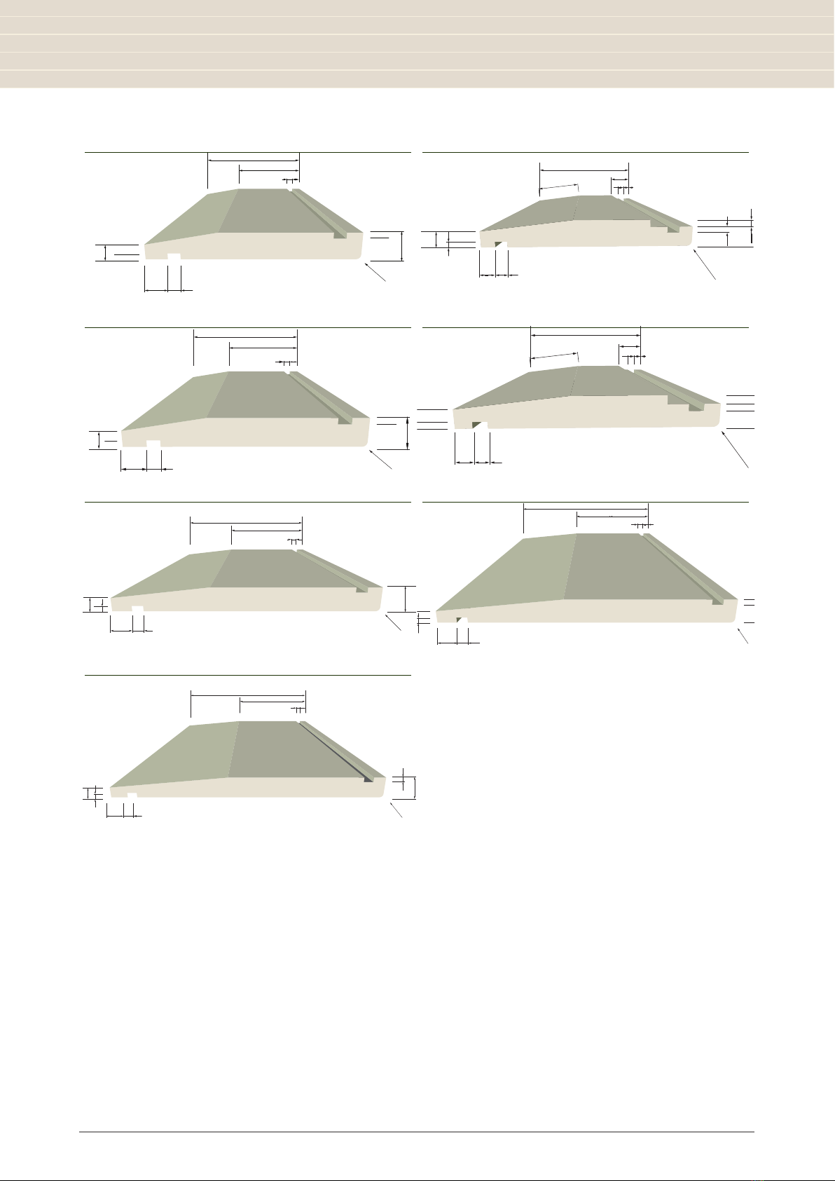
The blanks are then kiln dried (KD) to a pre-determined moisture content. The KD H3.2 substrate is then profiled to various
Weatherboards, Fascia, Finishing Boards (D4S), box corners and other profiles.
To complement these appearance grade products, a dual coat oil based (alkyd) priming system is applied.
Note: Pre-priming does not waterproof the product and care must be taken to ensure dryness of product before final
painting.
When using pre primed weatherboards and fascia ensure top coat painting occurs soon as possible after installation.
Refer 4.0 Painting page 18
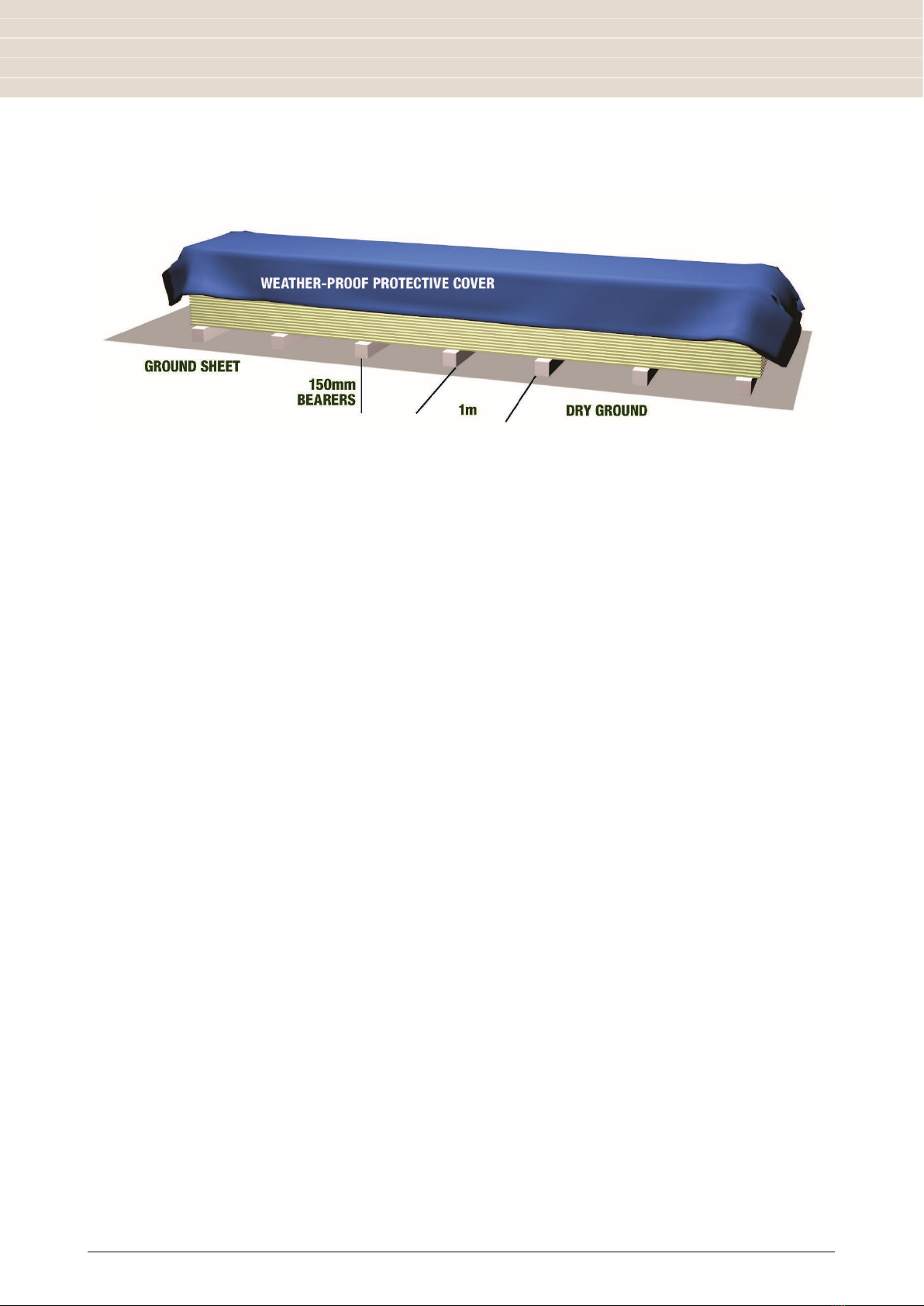
KLC will not “Warranty” any Generation 2 H3.2 product that have not been stored correctly and installed by a professional
Licenced Building Practitioner and as per the NZ Building Code NZS 3604 and painted in accordance with AS/NZS 2311
2017.
KLC Generation 2 exterior cladding systems have been designed for use in residential and small commercial building
applications.
KLC Generation 2 H3.2 exterior cladding systems shall be either direct fixed to framing over a wall underlay or fixed to a
Generation 2 H3.2 cavity batten, this method is described in the Acceptable Solution E2/AS1 paragraph 9.1.8.
Timber weatherboards are included in the Acceptable Solution E2/AS1, section 3.0.
All types of weatherboard profiles may be used in low risk buildings. Only bevel back, rusticated and vertical shiplap
weatherboards should be used in high risk buildings. For information on requirements for rained ventilated cavities refer to
the Acceptable Solution E2/ AS1, paragraph 9.1.8.
KLC Generation 2 H3.2 weatherboards are limited to use in buildings with a risk matrix score of 20 or below as outlined in
E2/AS1 paragraphs 3.4.1 to 3.4.3 (Weather Tightness Matrix)
Weatherboard cladding systems are an acceptable solution under the terms of the New Zealand Building Code E2/AS1.
NZBC E2/AS1 section 1.5 specifies that the design, installation and alteration of cladding is classed as restricted building
work.

6
KLC Generation 2 H3.2 Installation and Technical Guide
1.3 Architects/Designers Responsibility
We have made the drawings as accurate as possible. We have even specified extra flashings in some areas that are over
and above the NZ Building Code E2/AS1 External Moisture.
But it is the Architects/Designers responsibility to confirm the suitability of these details for his/her particular project and
the client.
The Architect/Designer will need to determine the RISK MATRIX that is project specific, that then determines the details
required.
Builders that have questions about these details will need to contact the project specific Architect or Designer.
1.4 Legal Information
KLC Ltd and its Agent AIPdesignNZ Ltd have no reason to believe the information in the details are inaccurate.
KLC Ltd and its Agent AIPdesignNZ Ltd does not warrant the accuracy, adequacy or completeness of such information and
we do not undertake to keep the information in the details updated.
KLC Ltd and its Agent AIPdesignNZ Ltd DOES NOT:
a. Give any assurances that the details and information will be suitable for your purposes and you agree that you will not
rely on the information and you will make your own independent assessments (with the aid of qualified independent
advise).
b. Accept responsibility for any loss, damage (including indirect, special or consequential loss or damage), however
caused (including through negligence) that you may directly or indirectly suffer in connection with your use of or
reliance on the KLC Ltd and AIPdesignNZ Ltd Details. Any condition, warranty, right or liability which would otherwise be
implied is excluded.
1 General Information

7
KLC Generation 2 H3.2 Installation and Technical Guide
1 General Information
1.5 On-Site Storage and Handling – KEEP IT DRY
Correct on-site storage of Generation 2 H3.2 products prior to installation is critical.
Ensure the product is stored on site correctly. Inside, under cover or as per the diagram above if stored outside.
• MUST remain dry at all times prior to installation.
• MUST be stored indoors on a flat surface off the ground, on bearers 150mm above ground, supported every one
metre.
• If stored outside, there MUST be a moisture barrier (ground sheet) under the stack and a secondary waterproof
cover. Allow for a good air circulation.
• Keep out of direct sunlight and protected from both rain and ground moisture uptake.
• Ensure that the framing and cavity battens are dry prior to installation. The underside of the weatherboard is
vulnerable to water ingress. The moisture content must not exceed 15% at time of installation.
Note: Generation 2 H3.2 products are made from kiln dried timber. Timber will absorb moisture in a damp environment and
release it in a dry environment. If Generation 2 H3.2 products do absorb moisture prior to installation, dimensional swelling
may occur, this will disappear when the timber returns to its original moisture content. If the boards have become wet,
check the dimensions of the profile. If the dimensions are larger than the specification leave the boards to dry and regain
correct profile specifications before installation.
Handling
Care should be taken when unloading KLC Generation 2 product. The profiles should be unloaded by hand or with a
Hiab forklift, ensure that there is a minimum of 2 well-spaced load points to avoid excessive bending or flexing during
unloading.
• Do not tip these products from a truck.
• Avoid scratching the face of the board.
• Always carry profiles products on their edge to avoid excessive bending.
• Avoid leaning against any vertical surface to avoid any bending.

8
KLC Generation 2 H3.2 Installation and Technical Guide
2 Life Serviceability
2.1 Warranty
KLC Generation 2 weatherboards have a durability warranty based on the Treatment Manufacturer’s 50-year limited
guarantee.
Under the New Zealand Standards NZS 3602:2003 Timber Wood Based Products, weatherboards and cladding products
must have a minimum durability of 15 years.
The life service is subject to correct installation, paint coating of the product, maintenance and care.
When KLC Generation 2 weatherboards are installed according to the instructions contained in this manual and by a
Licenced Building Practitioner (LBP) or suitably qualified person, the service life can be expected to be considerably longer.
Full details covering all the aspects of pre-installation care, installation, painting and maintenance are contained within this
manual.
Bevelback Weatherboard Measurement Table
Bevel Back Profile Sizes Finish Grade Lap Cover Length Lm/m2
135x18 Finger Jointed 32mm 103mm 6.3m 9.71
135x18 Rebated Finger Jointed 32mm 103mm 6.3m 9.71
142x18 Finger Jointed 32mm 110mm 6.3m 9.09
142x18 Rebated Finger Jointed 32mm 110mm 6.3m 9.09
187x18 Finger Jointed 32mm 155mm 6.3m 6.45
215x18 Finger Jointed 32mm 183mm 6.3m 5.46
230x18 Finger Jointed 32mm 198mm 6.3m 5.05
Full details covering all the aspects of pre-installation care, installation, painting and maintenance are contained within this
manual. Bevelback Weatherboard Measurement Table.

9
KLC Generation 2 H3.2 Installation and Technical Guide
3 Guidelines for Installation
135 x 18 135 x 18 Rebated
135
14
10
4
8
89.22
18
R3
4
810
135
27
88
59.65
4
513
R3
9 8
4
11
142 x 18 142 x 18 Rebated
142
93.15
810
18
R3
4
814
10
4
142
27
88
59.65
4
513
R3
9 8
4
11
187 x 18 215 x 18
187
14
10
4
8
R3
18
118.11
8 10
215
14
9
4
8
4
18
R3
810
123.5
230 x 18
810
131
230
14
4
9
8
18
R3
4
The products should be installed by a competent qualified person in accordance with the provisions of the Building Code
E2/AS1 (sec 9.4) and NZS 3604 (2011). For further information visit BRANZ Good Practice Guide, Timber Cladding.

10
KLC Generation 2 H3.2 Installation and Technical Guide
3 Guidelines for Installation
3.1 Pre-Installation Checks
There are many simple checks that should be carried out prior to installation which can avoid issues during installation.
• Where any KLC Generation 2 profile has been exposed to moisture prior to installation, the moisture content
should be checked. If the moisture content is above 15% then the product should not be installed until it returns to
15% or less.
• When excessive moisture or swelling is found the profile should be put aside and allowed to dry to its original
profiled dimensions. This is best done by placing the product in fillet and stored as outlined above. Filleting allows
air movement through the boards for drying.
• Check for any defects or damage caused during delivery or storage.
• Remove any dirt, dust or stones which may be on the product.
• If there are any areas where a primer coat has been removed or damaged, the affected area should be sanded
smooth and a primer coat applied.
• This product is primed with a factory applied alkyd (oil based) architectural coating, a similar oil-based undercoat
or primer must be used for touch-up work
• If building in “sea spray or geothermal zones”, it is the building designer’s responsibility to ensure all specified
fastenings, fittings, and flashings comply with NZS 3604, Section 4 – Durability.
3.2 Framing
• The timber framing must comply with NZS3604 – Timber Famed Buildings with maximum of 600mm centres.
• The moisture content of the framing must not exceed 20% at the time of fixing the weatherboard. Excessive
moisture content in the timber framing may cause movement in the framing structure thus altering the
weatherboard positioning.
• Additional framing may be required at soffit, corners, windows and door opening

11
KLC Generation 2 H3.2 Installation and Technical Guide
3 Guidelines for Installation
3.3 Nail Selection
KLC Generation 2 H3.2 weatherboards are treated using the revolutionary water based micronised copper timber treatment
technology called “MicroPro”.
• In most applications both stainless steel and hot dip galvanised steel fixings and fasteners are safe to use with
MicroPro®treated exterior products. Compliant to AS/NZS 4680 and to NZBC E2/AS1 Table 24.
• Note In sea-spray and Geothermal zones nails must be Stainless Steel.
• Hand nailing is recommended as the use of nail guns can cause fibre damage to the face and back of the board.
Based on MicroPro®ISANTA fastener corrosion test results, MicroPro®treatment is considered similar to CCA treatment
with regard to the effects on fastener material. Therefore, in most applications both stainless steel and hot dip galvanised
steel fixings and fasteners are safe to use with MicroPro®treated exterior products. Compliant to AS/NZS 4680 and to NZBC
E2/AS1 Table 24.
Nail Option A Nail Option B
One Nail to Framing
(refer E2/AS1 - Table 24)
Structurally Fixed Cavity Batten
(Refer BRANZ Bulletin No 582 & Test Report ST0589)
Weatherboard & Cavity Batten Fixing
90 x 3.55mm Jolt Head, Hot Dip Galvanised Nails
OR
75 x 3.15mm CSK Annular Grooved, HD Galvanised Nail
75 x 3.15mm CSK Annular Grooved, SS Nail
BATTEN FIXING OPTION
60 x 2.8mm Jolt Head, Hot Dip Galvanised Nail
65 x 2.87mm Power Driver, Hot Dip Galvanised Nail
65 x 2.87mm Power Driver, Annular Grooved SS Nail
Bevelback Nail Selection Table
Timber size (mm) Generation 2 profile Recommended minimum nail size
135 x 18, 142 x 18, 180 x 18, 187 x 18, 215
x 18 and 230 x 18
Bevelback direct fixed weatherboards 75 x 3.15
135 x 18, 142 x 18, 180 x 18, 187 x 18, 215
x 18 and 230 x 18
Bevelback cavity fixed weatherboard 75 x 3.15
85 x 18 & 100 x 18, 100 x 100 cover External and Internal Box Corners 50 x 2.50
All sizes D4S Finishing Boards 50 x 2.00
40 x 18 Scriber 50 x 2.00
45 x20 Cavity Batten 60 x 2.80

12
KLC Generation 2 H3.2 Installation and Technical Guide
3 Guidelines for Installation
3.4 Installation
• Installation must be by a Licensed Building Practitioner (LBP), or supervised by an LBP. Please refer to BRANZ Bulletin
Number 468, Fixing of Timber Weatherboards or refer to detail drawings contained in this document or online.
• Using a TP (timber packer), position and fix the bottom weatherboard. Ensure there is a minimum of 50mm overlap
below the bottom plate or bearer. The purpose of a TP is to provide the accurate layback angle for the bottom board.
• Use 75 x 3.15 JH hot-dipped galvanised or annular grooved stainless steel nails for fixing either directly into the framing
or structural batten.
• Leave a 2mm expansion gap in the lap of rebated profiles, ie Rusticated & Bevelback to allow for expansion and
contraction.
• Boards must be single nail fixed to allow for seasonal movement, with an overlap of 32mm.
• Single nail all weatherboard profiles, regardless of size. Nailing boards together will likely result in split boards.
• Hand nailing is recommended as nail guns can cause damage to the surface of the board. If a nail gun is used, a non-
marking attachment should be used to avoid damage to the surface.
• Nails must have a minimum penetration of 35mm into the wall framing or structural batten. Refer drawing CF20 BB44,
CF20 BB44+ and DF BB44.
• Pre-drill all boards 50mm from the end to avoid end splitting.
• Nail holes should be pre-drilled especially in areas around joins and the end of boards. This is to avoid splitting the
product.
• Location of the nails is to be a maximum overall distance of 42mm from the bottom edge of the board. 32mm minimum
overlap and 10mm to the nail fixing point. Aligning the weather grooves.
• Nails should be applied at an upward angle of 10degrees to avoid water entering through the fixing point.
• All nails should be punched to a depth of no less than 2mm.
• As soon as nails are punched below the surface of the weatherboard, they must be filled with an exterior grade filler
immediately to prevent moisture uptake in the weatherboards.
• The top board may need to be cut to suit the soffit.
IMPORTANT NOTE: Timber weatherboards are designed to accommodate thermal, seismic and moisture related movement
in the board laps. Each weatherboard is single nailed so that the weatherboards can expand, contract and move
independently of each other. KLC does not recommend the use of any sealant/glue being used by the painters under the lap
of each board, this inhibits the natural and ongoing movement of the weatherboard.

13
KLC Generation 2 H3.2 Installation and Technical Guide
3 Guidelines for Installation
3.5 Joins and Pipe Penetrations
It is an industry recommendation that all forms of timber treated products, when cut, have a cut-end treatment applied (e.g.
a zinc naphthenate-based product like Reseal Clear or Protim) which restores the treated envelope. This refers to MCA, CCA
and LOSP treated products.
KLC’s manufacturing and tested treating process and the inclusion of the two coat oil based priming system being applied
to all of the Generation 2 profiles, KLC recommends that all during the installation process, cut ends, drill holes, rebates and
notches must be re- sealed/primed immediately with a suitably approved product.
KLC recommends following best building practices and industry recommendations which includes the use and application
of end seal treatment product or alternatively 2 coats of an oil based primer being brush applied.
KLC recommends the use of Koppers “Protim Reseal”.
End sealing can be achieved by the application of 2 coats of brush-applied, quality Alkyd (oil based) primer allowed to dry
between coats.
Joining Weatherboards
Refer CF& DF BB45 & BB45
Avoid joining Generation 2 H3.2 weatherboards whenever possible, but if unavoidable use a 45-degree scarf joint directly
over studs or Generation 2 H3.2 FJ Cavity Batten. Care must be taken to angle mitre joints away from the prevailing
weather, and or use Flat Soakers. Alternatively, a butt join is acceptable using flat soakers.
Face the overlapping board away from the prevailing weather direction using one fixing through the overlapping board (pre-
drill the hole to avoid splitting). Re-prime the cut ends.
Nails should be driven and punched below the surface to allow for filling.
Prime then fill with an exterior grade wood filler immediately after nailing.
Apply two coats of an Alkyd (oil based) primer or end sealer.
Pipe Penetrations
Refer to drawings CF & DF BB54 & BB55
Pipes to have a 5º Slope to the outside.
A flexible flashing tape with a minimum 0f 10mm coverage around the outside.
Install as per the manufacturer’s instructions
Apply two coats of an Alkyd (oil based) primer or end sealer.
3.6 Wall Underlay and Flashing Tapes
Refer Drawings CF & DF BB13, BB23
Use only underlays that meet the requirements of E2/AS1 Table 23
3.7 Windows and Door Openings
Refer Drawings: WINDOWS – CF & DF, BB10, BB11, BB12 & BB13
Refer Drawings: DOORS – CF & DF, BB20, BB21, BB22 & BB23
Refer Drawings: METER BOX – CF & DF, BB30, BB31, BB32 & BB33

14
KLC Generation 2 H3.2 Installation and Technical Guide
3 Guidelines for Installation
3.8 Flashings
Refer drawings CF & DF BB13, BB23 & BB33
Refer to NZS3604 section 4 and E2/AS1 Table 20 for durability requirements and E2/AS1 section 9 for flashing design and
fabrication details.
3.9 Sealants
All sealants must be suitable for exterior use and while they will assist with providing weathertightness at laps and joins
they must not be relied on to provide total protection.
3.10 Air Seals
Air seals are a barrier that prevent air flowing into the building. Air seals are required where a hole or penetration
through the external cladding occurs – windows, doors, pipes, meter boxes etc. See E2AS1 for complete building air seal
requirements.
A foam backing rod of a suitable diameter must be installed in the gap, a sealant to the perimeter that forms a waterproof
air seal prior to applying the sealant.
Backing rods and sealants must be used in accordance with the manufacturer’s instructions
3.11 Wall Cladding Cavities
Refer Drawings CF & DF BB44
If the weathertightness risk score is higher than 6 a drained and ventilated cavity will be required between the underlay and
Generation 2 weatherboards.
If a cavity is required, structurally fix Generation 2 treated cavity battens to the framing in accordance with BRANZ Bulletin
582. Cavity construction, Including flashing and vermin proofing, must be in accordance with the requirements as set out in
E2/AS1 and NZS4229.
Structurally Fixed Cavity Batten (Refer BRANZ Bulletin No 582 & Test Report ST0589)

15
KLC Generation 2 H3.2 Installation and Technical Guide
3.12 External and Internal Corner Details
Refer to drawings CF & DF BB40, BB41+, BB42 and BB43
Using 50x2.5mm JH hot dipped galvanised or annular grooved stainless-steel nails, fix the Generation 2 Box Corner two-
piece box corner profiles over the Generation 2 weatherboards. Use two nails at each fixing point. There must be a minimum
50mm cover on both faces of the corner.
Fixings must be located 35-40mm above the lower edge of the overlapping board on every fourth board for every
142mm wide weatherboard, every third for the 215 and 187x18 weatherboard and every second for the 230x18 wide
weatherboards. For nails near the ends of the corner boards pre-drill the nail holes.
Install a Generation 2 scriber over the weatherboards against the corner boards. Pre-drill holes and using 60x2.8mm (40x18
scriber) or 50x205mm (40x10 scriber) JH hot dipped galvanised or annular grooved stainless-steel nails, fix the scriber
firmly against the box corner. Nail at 450mm centres.
Re-prime the cut ends with two coats of and alkyd (oil based) primer, allowing to dry between coats.
Nails must be hand driven and punched below the surface to allow for filling. Prime then fill with an exterior grade wood
filler immediately after nailing.
3.13 External and Internal Box Corner details
Refer to drawings CF & DF BB50, BB51 AND BB53
Internal corners, direct or cavity fix, must have a flashing behind the cladding that provides a minimum 50mm cover to
both faces of the corner. Refer to E2/AS1 for full details. Using 50x2.5mm JH hot-dipped galvanised or annular grooved
stainless-steel nails, fix the Generation 2 two piece prefabricated internal box corner over the Generation 2 weatherboards.
Use two nails at each fixing point. The Generation 2 internal box corner provides 100mm cover on both faces of the corner.
Fixings must be located 35-40mm above the lower edge of the overlapping board on every fourth board for every
142mm wide weatherboard, every third for the 215 and 187x18 weatherboard and every second for the 230x18 wide
weatherboards. For nails near the ends of the corner boards pre-drill the nail holes.
Fit a pre-cut Generation 2 scriber over the weatherboards against the corner boards. Pre-drill holes and using 60x2.8mm
(40x18 scriber) or 50x205mm (40x10 scriber) JH hot dipped galvanised or annular grooved stainless-steel nails, fix the
scriber firmly against the box corner. Nail at 450mm centres.
Re-prime the cut ends with two coats of and alkyd (oil based) primer, allowing to dry between coats.
3 Guidelines for Installation

16
KLC Generation 2 H3.2 Installation and Technical Guide
3.14 Windows and Doors (Aluminium)
Refer to drawings CF & DF BB10, BB11, BB12 and BB13
Window and door openings are a high weathertightness risk area an require particular attention to ensure weathertightness
is achieved. All window and door openings must be constructed and trimmed in accordance with E2/AS1. All flashings, air
seals, underlay and flexible flashing tapes must be in place. For flashing details refer to NZS3604 section 4 and E2/AS1
table 20 for durability requirements and E2/AS1 for flashing design and fabrication details.
As recommended in E2/AS1, window and door suppliers are responsible for head flashings.
All windows must comply with NZS4211 including consideration of building location.
3.15 Window and Door Sills
Refer to drawings CF & DF BB11, BB21, BB22, BB23
The Generation 2 weatherboard system requires a full width sill tray for direct fixed windows and doors, which meets the
requirements of E2/AS1.
In a cavity fix application, all doors and windows with a trim opening wider than 600mm require an appropriate sill support
bar conforming to EMS, paragraph 9.1.10.5
3.16 Window and Door Heads
Refer to drawings CF & DF BB10 and BB20
Direct and cavity fixed aluminium windows and doors require a flashing that meets the requirements of E2/AS1. The
flashing must be fitted behind the cladding with a 5mm gap between the bottom edge of the cladding and the horizontal
surface of the flashing.
3 Guidelines for Installation

17
KLC Generation 2 H3.2 Installation and Technical Guide
As an alternative to nail fixing, fascia can be screwed onto rafter ends as wide as is practical with wide head (10mm)
Stainless steel screws, slightly countersunk. Screws should be a min. 75mm long.
Refer to drawing CF & DF BB63
4 Fascia Installation

18
KLC Generation 2 H3.2 Installation and Technical Guide
KLC Generation 2 H3.2 products have a premium factory applied alkyd primer and undercoat applied in two separate coats.
All painting must be carried out in a good tradesman-like manner and in accordance with AS/NZS 2311 2017. Please also
refer to “BRANZ Good Practice Guide to Exterior Coating”.
If boards have been exposed for longer than 4 weeks, some dimensional swelling or distortion of the board may have
occurred during unprotected exposure to the elements. Also, some sanding and re-priming may be required.
1. The moisture content of the boards before painting. Equilibrium Moisture Content (EMC) should be at 15% or less. Use
a correctly calibrated moisture meter to check.
2. Once installed, remove any dirt and surface contamination by sanding and dusting down. Spot-prime any exposed
timber with two coats of oil primer. Spot-prime the filled nail holes. Any sealants used should be of a flexible exterior
grade and suitable for over coating with acrylic paint
3. Once undercoated, simply apply two coats of 100% premium acrylic low gloss house paint to the manufacturer’s
specification, at a rate of 12-14m2/L.
4. Once applied, the two topcoats should have a combined thickness of no less than 50 microns. The Painter must adhere
to the topcoat paint manufacturer’s spread rate.
5. The onus is on the painter to ensure that the primed surface remains well adhered to the timber substrate and is a
suitable base for the subsequent topcoats. This is particularly important where the boards have been exposed for
longer than 4 weeks before top coating. Painters should refer to the AS/NZ 2311:2017 guide to painting buildings.
NOTE: The KLC warranty will be void if dark colours with a Light Reflectance Value (LRV) less than 45 are used.
6. Darker colours will absorb heat from the sun and may cause excessive movement, distortion, splitting and possible
resin bleed. Light colours reflect the suns heat. Therefore, only light colours with a light reflective value (LRV) of
greater than or equal to 45% may be used. Refer paint colour charts for details.
Top Coat Light Reflectance Values as recommended by KLC
The significance of Light Reflectance Values is now being recognized by the building industry. When paint
is exposed to sunlight it absorbs and reflects radiant heat (as well as UV light).
It’s not only radiant heat warming up the paint film that is the problem. Damage is caused by temperature
changes (i.e. from hot sun, cold to cloudy sky) causing the paint film to go through a process of heating up
then cooling down again resulting in changes in dimensional stability of the timber substrate. Increases
in the core temperature of the timber substrate can also cause resins to mobilise and leach through the paint film. This is
known as resin bleed.
Light paint colours with a high light reflectance (and therefore a high LRV over 45) allow less free radicals to be released,
which means the paint film and substrate will last longer. Correspondingly dark colours with a lower light reflectance allow
more heat to be absorbed, therefore causing more damage to the surface and resulting in reduced life for the paint film.
Resene Cool Colour Technology
• Resene Cool Colour technology reduces the amount of Infra-red heat absorption only into the substrate (it does not have
an effect on Visible light nor Ultra Violet which equates to 49% of Sunlight energy)
• Resene Cool Colour technology works best for Darker colours where Black tinter is used in the colour
• When using Resene Cool Colour the surface will still remain warm/hot to touch however less heat is being absorbed thru
into substrate
• LRV’s are only a measure of visible colour, not heat absorption which is better measured by TSR (Total Solar Reflectance)
therefore LRV’s are not altered when using Resene Cool Colours as the colour is the same (albeit that a Resene Cool
Colour will perform like a colour with a higher LRV)
• Resene advise customers that the use of Resene Cool Colour technology does not alter the LRV of the colour therefore
Suppliers/Manufacturers of substrates own guidelines on colour choice should always be followed unless that Supplier/
Manufacturer advises otherwise.
5 Painting
TOP COATS
45+LRV

19
KLC Generation 2 H3.2 Installation and Technical Guide
It is the responsibility of the home owner to ensure that annual maintenance is carried out.
Maintenance should be carried out every 12 months. In some cases, where a home is coastal this may be required more
regularly eg. 6 monthly.
Maintenance Checklist
1. Wash all exterior surfaces using a low pressure wash system to remove dust, dirt and other contaminants.
• Do not uses a high pressure washing system eg water blaster.
• If the washing does not remove stubborn areas of mold or dirt use a soft brush or broom and an appropriate
cleaning agent to remove these deposits. Check with the paint manufacturer and read the directions on the product
to apply the cleaning agent.
2. Once the building is clean and the surfaces have been inspected for damage, wear and tear and paint coating degrade
then repairs and must be undertaken immediately.
If the paint surface has been damaged, then:
a. Remove all damaged paint, sand back if required
b. Apply a quality primer on any bare timber
c. Once the primer has dried apply a base coat and then 2 top coats of a quality top coat paint.
3. It is a general rule that timber weatherboard homes should be repainted every 10 years if the initial coating product
used was of
6 Maintenance

20
KLC Generation 2 H3.2 Installation and Technical Guide
Health and safety precautions should be adhered to when working with all wood products.
Machine tools should be fitted with dust extractors and work areas should be kept clean.
If dust levels exceed Work Safe New Zealand Standards, the wearing of a dust mask (AS/NZS 1715 & AS/NZS 1716) and
protective eyewear (AS/NZS1336 & AS/NZS 1337) is recommended.
Storage and work areas should be adequately ventilated.
7 Health and Safety
Table of contents
Popular Construction Equipment manuals by other brands

Manitowoc
Manitowoc 8500-1 Service and maintenance manual

Lumag
Lumag LFR40 Operator's manual

Altrad
Altrad BELLE EASY SCREED PRO Operator's manual

SaMASZ
SaMASZ RP 110 Operator's manual

HYVA
HYVA AMCO VEBA 81 Series WARNING, OPERATING AND MAINTENANCE MANUAL

Venturo
Venturo ET18KXXP-20 PARTS & INSTALLATION MANUAL