kleenconnect LNI2-233 User manual

Automated
Forklift Entryway
Sanitizing System
Patented
INSTALLATION
AND
OPERATION MANUAL
6/15/2021

Installation & Operation Manual:
Automated Forklift Entryway Sanitizing System
_________________________________________________________________________________________________
1 | P a g e
Contents
......................................................................................................................................2
WARNINGS .........................................................................................................................................2
INTRODUCTION:.................................................................................................................................3
SPECIFICATIONS: ................................................................................................................................3
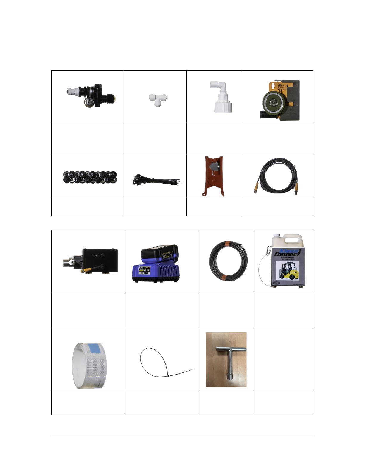
PACKAGE CONTENTS:.........................................................................................................................4
SYSTEM LAYOUT:................................................................................................................................5
TOOLS NEEDED TO INSTALL: ..............................................................................................................6
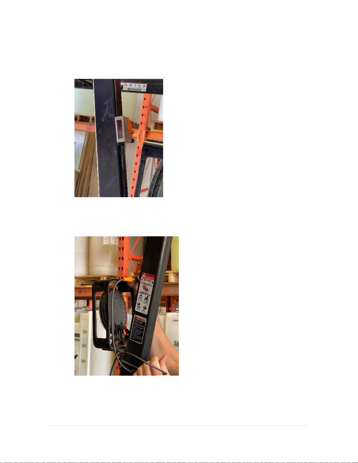
INSTALLATION INSTRUCTIONS:..........................................................................................................7
PRIMING THE SYSTEM:.....................................................................................................................17
SETTING THE PHOTO SENSOR:.........................................................................................................18
ADJUSTING THE NOZZLES: ...............................................................................................................18
SETTING THE REFLECTIVE STRIPS:....................................................................................................19
SETTING THE SPRAY (RUN) TIME:....................................................................................................20
OPERATING THE SYSTEM: ................................................................................................................20
REFILLING THE SANITIZER:...............................................................................................................21
WARRANTY:......................................................................................................................................23
BATTERY USER GUIDE: .....................................................................................................................23

Installation & Operation Manual:
Automated Forklift Entryway Sanitizing System
_________________________________________________________________________________________________
2 | P a g e
READ ALL INSTRUCTIONS BEFORE ATTEMPTING TO INSTALL AND OPERATE THIS EQUIPMENT
WARNINGS
Read this manual completely before attempting to install or use this system.
•Always wear proper personal protective equipment (PPE’s) when installing or servicing
this unit.
•Always follow all chemical safety precautions and handling instructions provided by the
chemical manufacturer or product Safety Data Sheet (SDS).
•If this unit is modified or serviced with parts not listed in this manual, the unit may not
operate correctly and may void any warranty.
•Chemical Spray Hazard: Wear splash goggles or glasses when required by chemical
manufacturer, SDS, or OSHA when installing or servicing this unit.
•Magnet Warning (physical injury):
oThis unit uses very strong magnets. Care must be taken when handling to prevent
pinch and other personal injuries. Serious injury can occur to fingers if caught
between large magnets. Small magnets can be a choking hazard and should never
be swallowed or inserted into any part of the body. Small magnets are
considered a choking hazard that can result in death and should be treated as
such. Keep all magnets away from animals and children. If a magnet should
break gather all small pieces and dispose of accordingly.
•Magnet Warning (magnetic field):
oTHIS UNIT CONTAINS MAGNETS THAT MAY BE HARMFUL TO THOSE WEARING A
PACEMAKER OR OTHER DEVICE SENSITIVE TO MAGNETS.

Installation & Operation Manual:
Automated Forklift Entryway Sanitizing System
_________________________________________________________________________________________________
3 | P a g e
INTRODUCTION:
This system is designed to aid in the sanitizing of wheels on forklifts prior to entering and exiting
critical control areas, especially where reduced moisture is advantageous. This system has been
designed to provide an uninterrupted uniform distribution of sanitizer solution onto the tire tread
surface. The application of sanitizer is initiated manually by the operator or by automatic
signaling from the controller circuitry, causing the pump to dispense approximately 1.0 ounce of
sanitizer evenly split to all nozzles. Any modification or alteration of the system may result in
poor performance which may include uneven spray patterns, interrupted spray, or excessive
dripping of sanitizer. To avoid these issues it is highly recommended that only authorized parts or
components be used in this system.
SPECIFICATIONS:
Dimensions: Shipping package size, approximately 12” x 12” x 12”
Shipping Weight: without sanitizer, approximately 19 lbs.
Pump Capacity: 1 liter per minute @45-55 PSI
Serial Number _____________________ (located on underside of pump cover)
Date purchased / Installed _____________________

Installation & Operation Manual:
Automated Forklift Entryway Sanitizing System
_________________________________________________________________________________________________
4 | P a g e
PACKAGE CONTENTS:
(4 ea) Fan Nozzles With
Swivel Adapters,
Screens, Check Valves,
& Magnet Mounts
(3 ea) ¼” Push-Fit
Tee Fittings
(1 ea) Gallon Jug
Adapter Cap,
Push-Fit Tubing
Connector
(1 ea) Photo Electric
Sensor Assembly With
Magnet Mount
(20 ea) Magnetic Tie
Mounts
(25 ea) Small Plastic
Cable Ties
(1 ea) Tubing
Cutter
(1 ea) Sensor Connector
Cable
(1 ea) 24 VDC Pumping
Module & Controller
(1 ea) Battery Charger
(2 ea) 4.0 Ah Batteries
(50 Ft) 1/4"
Black PE Tubing
(1 ea) Sanitizer Jug
Rack With Magnetic
Mounts And Safety
Cable Assembly
(4 ea) 24” Adhesive
Backed Strips
Reflective Tape
(1 ea) Large Plastic Cable
Tie
(1 ea) Dip Tube
Removal Tool

Installation & Operation Manual:
Automated Forklift Entryway Sanitizing System
_________________________________________________________________________________________________
5 | P a g e
SYSTEM LAYOUT:

Installation & Operation Manual:
Automated Forklift Entryway Sanitizing System
_________________________________________________________________________________________________
6 | P a g e
TOOLS NEEDED TO INSTALL:
Adjustable Wrench
Used to tighten nozzle bodies and
adjust nozzles
Pliers
Used to tighten nozzle bodies and
adjust nozzles
Angle Cutters
Used to cut plastic ties
Tape Measure
Used to measure sensor height
Tubing Cutter (provided)
Used to cut tubing
NOTE
All components of this system are attached to the vehicle with magnets. The only tools needed
for installation are an adjustable wrench, pliers, diagonal cutters, tape measure, and the tubing
cutter supplied in this kit. The tubing connections are a push-fit style connection which when
firmly pushed into the fitting will provide a tight, leak free connection. To release a push-fit style
connection, press in on the fitting collar while pulling on the tubing.

Installation & Operation Manual:
Automated Forklift Entryway Sanitizing System
_________________________________________________________________________________________________
7 | P a g e
INSTALLATION INSTRUCTIONS:
READ ALL INSTRUCTIONS BEFORE INSTALLING THIS EQUIPMENT
1. Unpack the entire contents and inspect to ensure all components shown on page 4
“Package Contents” are included. Open the battery and charger packaging. Place one
battery on the charger to begin charging.
2. Review the vehicle this unit will be installed on and determine which location is desired
for placement of the one-gallon sanitizer jug rack. The jug rack can be attached by either
the bottom mount magnets or the side mount magnets. Keep in mind that the jug rack
can be moved to facilitate inspections and maintenance. You may want to identify a
location that is the best fit during use, such as inside the ROP upright and another during
inspection, such as outside the ROP upright.
Figure 1
Figure 2
3. The jug rack includes a safety cable that prevents the unit from falling to the ground if it is
accidentally knocked off the vehicle. This safety cable will need to be attached to the vehicle
roughly 18 inches above the jug rack. This will allow about 5 inches of slack in the cable. The
safety cable and clip are visible in figures 2 and 3. If you plan to use alternate locations for the
jug rack, make sure there is enough slack in the cable to allow movement to each of the
alternate locations.
Attach the clip using the supplied large plastic cable tie. Route the cable tie through the small
closed end of the clip and secure it around the upright or other object (figure 4). Ensure the
cable clip gate is easily accessible as the loop end of the cable will need to be removed from
the clip each time the jug is replaced.

Installation & Operation Manual:
Automated Forklift Entryway Sanitizing System
_________________________________________________________________________________________________
8 | P a g e
Figure 3
Figure 4
4. Determine the desired location for the pumping module. Usually behind the operator’s
seat. Attach the pump by setting the base mounted magnets on a suitable metal surface.
Ensure the magnets hold the pump securely in place. Ensure the pumping module will not
interfere with seat adjustment or daily/shift inspections. The magnets do allow
repositioning for service, but it is advisable to not require repositioning for daily/shift
inspections. (Figure 5)
*Note.
If the desired pump module location is
non-metallic, a steel plate (not provided)
can be attached to the forklift to mount
the pump.
Figure 5
5. Determine the location of the photo-electric sensor. The sensor should be placed in a
convenient location with the sensor glass pointing away from the forklift, perpendicular to
the vehicle’s travel path. It should be placed at a height that will be equal to the reflective

Installation & Operation Manual:
Automated Forklift Entryway Sanitizing System
_________________________________________________________________________________________________
9 | P a g e
tape you will be installing at each entryway/doorway It is recommended to install the
sensor on the A pillar (closest to the mast) pointed to the right hand side of the entryway.
This will permit the sensor to see the reflective tape upon entry and not on exit. (Figure 6)
Figure 6
6. Connect the sensor cable to the sensor using the M12 connector. Hand tighten only. Do
not use tools to tighten the connectors. (Figure 7)
Figure 7
7. Starting with the sensor cable at the sensor, route the sensor cable along the roll cage
using the provided magnetic tie mounts and ties. When routing the cable, do not draw the
ties up snug yet, as you may need to include the chemical tubing in these ties to attach to
the nozzles at the front of the forklift. Once you have routed the sensor cable back to the

Installation & Operation Manual:
Automated Forklift Entryway Sanitizing System
_________________________________________________________________________________________________
10 | P a g e
location of the pumping module, Lay the remaining cable next to the pumping module
and advance to the nozzle locations.
Figure 8
8. Find the positions on the body of the vehicle that will allow the nozzles to point to the tire
tread with at least a 2 to 3 inch spacing. If the nozzle is located too close to the tire it will
not cover the entire tread surface area. If it is located too far away from the tire it will
spray wider than the tire tread surface area and waste sanitizer. Affix the nozzles for all
three or four tires, depending on the lift. Have an assistant turn the steering through the
complete range of motion while you observe and ensure clearance with the nozzles. Pay
attention to anything that might contact the nozzles. Relocate the nozzles if necessary.
Figure 9
NOTE: The kit comes with nozzle assemblies set for each side of the forklift, (2) left and
(2) right. If required, you may remove the clamp from the nozzle assembly and reverse if

Installation & Operation Manual:
Automated Forklift Entryway Sanitizing System
_________________________________________________________________________________________________
11 | P a g e
needed to properly locate the nozzles. Determine which locations and configurations
work best for your particular installation. (Figures 10 & 11)
Figure 10
Figure 11
Final positions and angles can be adjusted after installation to achieve optimum coverage.
The nozzle bodies also provide tilt and swivel adjustment to fine tune the spray location.
(Figure 12)
Figure 12

Installation & Operation Manual:
Automated Forklift Entryway Sanitizing System
_________________________________________________________________________________________________
12 | P a g e
9. With the jug rack, pumping module, and nozzles located, you may now install the
chemical tubing. Start by placing a one gallon container of sanitizer in the jug rack. Unclip
the safety cable from the cable clip and route the cable through the handle of the jug and
then reattach to the clip. (Figure 13)
Figure 13
Remove the cap from the sanitizer jug and attach the one-gallon adapter cap assembly by
pushing down firmly as you turn the adapter clockwise. Insert the ¼” PE tubing into the
push-fit fitting on the adapter cap and press firmly until the tubing is fully seated into the
fitting. * Note. It is important that the tubing end be cut square and to press it in straight.
Do not force the tubing or press at an angle. The tubing should insert approximately 1/2”.
(Figure 13)
Route the tubing from the one-gallon container to the pumping module and mark the cut
location using a piece of tape. (the tape from the tubing wrap works well for this) DO NOT
CUT THE TUBING AT THIS POINT. Lift the engine inspection cover and or seat, depending
on your lift design, and ensure that the tubing does not get in the way or become
pinched. If this requires temporarily moving the jug rack to an alternate location for
inspection, you may move it. Be sure to leave enough extra tubing to allow both locations.
(Figure 14)

Installation & Operation Manual:
Automated Forklift Entryway Sanitizing System
_________________________________________________________________________________________________
13 | P a g e
Figure 14
Now pull the jug rack loose from the vehicle and allow it to be suspended by the safety
cable. Ensure that the tubing from the jug to the pump does not get pulled tight or placed
under any strain. Allow extra tubing if necessary.
Figure 15
Once you have determined the desired routing for the tubing from the one-gallon jug to
the inlet of the pump, you may attach the tubing using several of the magnetic mounts
and plastic ties.

Installation & Operation Manual:
Automated Forklift Entryway Sanitizing System
_________________________________________________________________________________________________
14 | P a g e
SAFE TUBING INSTALLATION QUICK CHECK:Tubing is not kinked, pulled, or pinched…
With the jug rack in the normal operating position
With the jug rack in the alternate / maintenance / inspection position.
When the inspection cover or seat are lifted for maintenance or inspection
When the one gallon container is lifted from the jug rack
When the jug rack and one gallon container are suspended by the safety cable
10. With the tubing properly routed, establish the final correct length from the one gallon jug
to the pumping module inlet push-fit fitting and cut the tubing with the supplied tubing
cutter.
Note: The inlet tubing should be connected to the inlet side of the pump as shown below
Install the end of the tubing into the pumping module inlet fitting by pushing in until the
tubing is fully seated, just as in step 9. *Note, in all of these push-fit connections, you
should feel some resistance when pressing the tubing into the fitting, followed by the
tubing engaging into the fitting an additional ½”.
11. Install one end of the ¼” tubing roll into the discharge push lock fitting on the pump. (see
diagram above). Roll out enough of this tubing to reach the counter weight behind the
operators seat. Cut the tubing with approximately 6”additional tubing. Now position the
1st of the three push lock tees in a convenient location, typically in the middle of the
counterweight area.

Installation & Operation Manual:
Automated Forklift Entryway Sanitizing System
_________________________________________________________________________________________________
15 | P a g e
This tee splits the flow into two directions, one for the front and one for the rear.
Depending on your lift, these outlets will need to be split again to each nozzle previously
mounted near each tire. You can shorten the tubing later if desired.
With the 1st tee in position, install another piece of tubing to one of the open ends of the
1st tee and plan where an additional (2nd) tee will be installed to split the spray to each
rear wheel. Cut the tubing and install the 2nd tee.
*Note, Reference the System Layout on page 5 for the suggested tee configuration.
12. Next, starting at one of the rear wheel nozzles located on either side of the lift, attach the
black ¼” tubing to the spray nozzle push-fit fitting. Route the tubing up the body of the
forklift to the location of the 2nd tee installed in the previous step. Be sure to route the
tubing so that it is least likely to be damaged, kinked or smashed. Leave a couple inches
of extra tubing near the nozzle to allow minor adjustments to the nozzle location. Secure
the tubing with the magnetic tie holders and ties (figure 16) and cut the tubing to length.
Connect it to either side of the 2nd branch T.
Repeat for the rear wheel on the other side and connect to the other end of the 2nd
branch T. At this point, the installation of the rear spray nozzles and tubing is complete,
and you can now install the tubing for the front nozzles.
13. Starting at the front of the lift, follow the direction you used to install the sensor cable
and thread the tubing through the plastic ties that where loosely tied when installing the
sensor cable in step 7. Continue to route the tubing and connect it to the remaining open
end of the 1st tee. This should complete the plumbing on the rear of the lift. At this point
it is a good idea to again check for interference with inspection covers and/or seat
movement. Once you have ensured that the cable and tubing are correctly routed you
may tighten the plastic ties to secure both the sensor cable and the tubing. Connect the
Figure 16

Installation & Operation Manual:
Automated Forklift Entryway Sanitizing System
_________________________________________________________________________________________________
16 | P a g e
sensor cable to the pump system using the M12 connector. Hand tighten only. Coil
excess cable and tie out of harms way using the magnet mounts and ties
14. At the front of the forklift, find a location to install the 3rd branch T. Usually between the
mast and the front of the forklift body. (Figure 17)
Figure 17
Cut the tubing and install the branch T, then use the tubing and the magnetic mounts and
plastic ties to route each end of the branch T to the front spray nozzles. Connect the front
spray nozzles just as you connected the rear nozzles, leaving some slack if possible, to
allow adjustment of the nozzles.
15. Install a fully charged battery pack.
16. Once the installation is complete, walk around and check to make sure all tubing is routed
and secured properly. Open and close any engine compartment doors or access covers,
slide the seat fully forward and backward, and make sure there are no interferences with
tubing or components. (Figure 18) (Figure 19-showing temp relocation of jug rack)

Installation & Operation Manual:
Automated Forklift Entryway Sanitizing System
_________________________________________________________________________________________________
17 | P a g e
Figure 18
Figure 19
PRIMING THE SYSTEM:
The system is now ready for priming and use. Actuate the pumping module by pushing in
on the Prime Button and releasing. Each time the button is pushed the unit will run until it
times out. When the nozzles have achieved a spray pattern the priming is complete.
Check to make sure there are no leaks at connection points. Make sure all tubing
connections have been fully inserted into the push fit style fittings.
*Note, if the prime button fails to actuate the pump, it is most likely that the photo
electric sensor has been inadvertently switched into the wrong mode. To correct this
condition, See the section below on setting the photo sensor.
*Note, if the pump fails to prime after 3 or 4 actuations, disconnect the pump discharge
tubing from one of the nozzles or branch tee fittings and place in/over a suitable
container. Reattempt to prime the system again until some fluid exits through the
disconnected fitting. Once the pump has been primed you may reconnect the tubing to
the fitting. This method should only be required upon initial startup with a dry pump or
following an extended shutdown where the pump was allowed to completely dry out.

Installation & Operation Manual:
Automated Forklift Entryway Sanitizing System
_________________________________________________________________________________________________
18 | P a g e
SETTING THE PHOTO SENSOR:
The photo electric sensor should be pre-programmed when received. However, in the
event the sensor is not performing properly, ensure it is programmed properly by
performing the following:
•Align the sensor so there is no light reflected from the reflective tape.
•First press [OUT off], then [OUT on] on the photo electric sensor.
This will set the sensor in the proper mode and adjust for maximum sensitivity.
Electronic Lock: The photo sensor does have the ability to be electronically locked to
prevent unauthorized setting. On delivery, the unit is not locked. To lock or unlock,
follow these steps:
•Press [OUT on] and [OUT off] simultaneously for 10 seconds. Acknowledgement is
indicated by a change of the LED status.
ADJUSTING THE NOZZLES:
Have an assistant press the pump prime button while you observe the spray pattern at
each wheel. The goal is to achieve a flat fan spray that covers the entire width of the
wheel. (Figure 20) Adjust as required by placing the magnet mount in an alternate
location, adjusting the nozzle swivels, or turning the nozzle itself to align with the wheel.
Make sure to tighten the nozzle swivel assemblies as well as the caps. You may also trim
any excess tubing at this point. If you relocated the nozzles, be sure to re-check for
clearance when turning the wheels.
Figure 20

Installation & Operation Manual:
Automated Forklift Entryway Sanitizing System
_________________________________________________________________________________________________
19 | P a g e
SETTING THE REFLECTIVE STRIPS:
Take the forklift to a location, door opening or entryway area where you want the unit to
spray the tires. Note the height and angle of the photo sensor and the desired direction
of travel in relation to the sensor. Most installations will call for the reflective tape to be
installed on the right side of the entryway to permit operation when entering and not
when exiting.
Confirm that this height and angle will work for all desired entryways, then measure and
record the centerline height of the sensor. Using this measurement, apply one of the
adhesive-backed reflective strips at the appropriate height, such that when the forklift
passes the tape, the sensor will receive a reflected beam and activate the pump system.
Each provided strip is 24” in length. When installed correctly, the beam height should be
near the center of the 24” strip. This will allow some variability between lifts and
installations. For optimum beam reflection, the reflective tape and beam should pass at
90° angles relative to each other.
Install additional reflective strips at the same height at each desired door or entryway.
Photo Electric Beam Height _____________________
Reflective Tape Mounting Height__________ to bottom__________to top of strip.
Table of contents
Popular Forklift manuals by other brands

Xtreme
Xtreme XRM1145 Operation and safety manual

Xtreme
Xtreme XR1045 Alden TIER4 Operation and safety manual

Hyster
Hyster B238 Service manual

Sealey
Sealey DG06 quick start guide

cascade corporation
cascade corporation QFM Push/Pull E Series Installation instructions and periodic maintenance

Kubota
Kubota AP-PFL4648 owner's manual