Klemsan TES-4 User manual

User
Manual
TES
Transparent
Ethernet /
Serial
Converter

SECTION 1
1.1
1.2
SECTION 2
2.1
2.2
2.3
2.3.1
SECTION 3
3.1
3.1.1
3.1.1.1
3.1.1.2
3.1.1.2.1
3.1.1.2.2
3.1.1.3
3.1.1.4
3.1.2
SECTION 4
4.1
4.2
4.3
4.4
4.5
4.6
4.7
4.8
4.9
SECTION 5
Transparent Ethernet /
Serial Gateway
TES
2
TES
TABLE OF CONTENTS
GENERAL INFORMATION ......................................................... 4
Proper Use and Safety Conditions...................................................................... 5
General Futures ....................................................................................................... 5
DEVICE SPECIFICATIONS......................................................... 6
Denition on Device................................................................................................ 7
Conguring TES-4..................................................................................................... 8
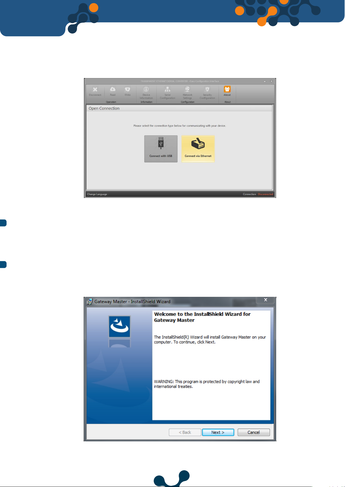
Required Installation for Conguration Software......................................... 9
Installing Configuration Software .................................................................. 9
CONFIGURATION SOFTWARE..................................................13
Connection Settings................................................................................................ 14
Connection Via USB................................................................................................. 14
Network Setting........................................................................................................ 15
Serial Conguration................................................................................................. 18
Port Settings............................................................................................................... 18
Data Packet Settings................................................................................................ 19
Device Information - Firmware Updates........................................................... 20
Security Conguration............................................................................................ 21
Connection via Ethernet......................................................................................... 22
JSON RestAPI .............................................................................23
General Communication Settings....................................................................... 24
Serial Conguration................................................................................................. 25
Instant Serial Conguration.................................................................................. 26
Network Settings....................................................................................................... 27
Security Conguration............................................................................................ 27
All Congurations..................................................................................................... 28
Product Information Functions........................................................................... 28
All Data......................................................................................................................... 30
Command Function................................................................................................ 31
TECHNICAL SPECIFICATIONS...................................................32
Transparent Ethernet /
Serial Converter

Gateway Master over USB....................................................................................... 8
Gateway Master over Ethernet ........................................................................... 9
Installing Configuration Software(Step 1)......................................................... 9
Installing Configuration Software(Step 2)......................................................... 10
Installing Configuration Software(Step 3)......................................................... 10
Installing Configuration Software(Step 4)......................................................... 11
Driver Setup (Step 1) ................................................................................................ 11
Driver Setup (Step 2) ................................................................................................ 12
Shortcut of the Configuration Program ............................................................ 12
Virtual Com Port that TES is connected ......................................................... 14
COM Port Selection ................................................................................................... 15
Network Settings ....................................................................................................... 15
Operating Principle of The Gateway ................................................................... 16
Serial Port Settings .................................................................................................... 18
Device Information ................................................................................................... 20
Firmware Update ....................................................................................................... 20
Security Settings ........................................................................................................ 21
Connection via Ethernet ......................................................................................... 22
Dimensions................................................................................................................... 33
Transparent Ethernet /
Serial Gateway
TES
Transparent Ethernet /
Serial Converter
3
TES
FIGURES
Figure 2-1
Figure 2-2
Figure 2-3
Figure 2-4
Figure 2-5
Figure 2-6
Figure 2-7
Figure 2-8
Figure 2-9
Figure 2-10
Figure 3-1
Figure 3-2
Figure 3-3
Figure 3-4
Figure 3-5
Figure 3-6
Figure 3-7
Figure 3-8
Figure 3-9
Figure 3-10
Figure 5-1
Definitions on TES-4.................................................................................................. 7
TABLE
Table 3-1 Default Network Settings of TES......................................................................... 17

5
SECTION 1
GENERAL
INFORMATION
TES
Transparent
Ethernet / Serial
Converter

SECTION 1 GENERAL INFORMATION
1.1
Proper Use and Safety Conditions
oInstallation and connections should be established in accordance with the
instructions set out in the manual by authorized persons. Unless the
connection is built properly, device should not be operated.
oBefore wiring the device up, make sure that energy is cut off
oUse a dry cloth to remove the dust from the device/clean the device. Avoid
using alcohol, thinner or a corrosive material
oDevice should be engaged only after all the connections are made.
oDo not open the inside of the device. There are no parts which the users
can intervene inside.
oDevice should be kept away from humid, wet, vibrant and dusty
environments.
1.2 General Futures
TES-4 Order No: Explanation:
601410 TES-4 (Transparent Ethernet/Serial Converter)
TES is a transparent converter that provides bidirectional transmission with RS485 interface
running on server role using TCP / IP infrastructure. In this way, it is possible to control
and monitor serial devices remotely, regardless of communication protocols.
Additionally, the configuration data of the device can be read and written in USB or
JSON format.
TES generally has the following features:
•Runs in the server role
•Supports bidirectional communications
•Supports 2 remote connections
•Works as a transparent converter
•Supports Ethernet 10/100 Base Tx
•Can be configured over USB and Internet
•Can be change the serial communication settings instantly
•Access to all configuration functions and information through fully open JSON Rest API
•Software update via USB
The manufacturing company may not be kept responsible for unfavorable incidents
that arise out of the failure to follow the above cautions.
Transparent Ethernet /
Serial Gateway
TES
Transparent Ethernet /
Serial Converter
5
SECTION 1GENERAL INFORMATION
TES
l
l
l
l
l
l

5
SECTION 2
DEVICE
SPECIFICATIONS
TES
Transparent
Ethernet / Serial
Converter

SECTION 2 DEVICE SPECIFICATIONS
2.1 Definition on Device
U1-U2 Input:
TES-4 is powered on from U1-U2 input. 18 ... 50V AC/DC must be
applied.
RST Button:
Press briefly (<5sec) to restart TES. Press and hold (≥ 5sec) and TES will restart by returning
to the factory settings.
ON LED:
When the LED color is orange, that means device is powered on from only U1-U2
input. When the LED color is blue, that means Micro-USB cable is connected to TES-4.
RX/TX LED:
These LEDs are orange when the data is sent from the serial line or sent to the serial from
the device.
Figure 2-1 Definitions on TES-4
Power Input
Reset Button
ON LED
Ethernet Port
RX/TX LED
USB Port
RS485
Terminals
Transparent Ethernet /
Serial Gateway
TES
Transparent Ethernet /
Serial Converter
7
SECTION 2DEVICE SPECIFICATIONS
TES

2.2 Configuring TES-4
Figure 2-2 Gateway Master over USB
Transparent Ethernet /
Serial Gateway
TES
Transparent Ethernet /
Serial Converter
8
SECTION 2 DEVICE SPECIFICATIONS
TES
Ethernet Port:
Ethernet cable must be inserted.
USB Port:
Micro-USB cable must be inserted to this port. Device can power on with USB port as
well. If operator wants to use Gateway Master must be connected to PC over micro-usb
cable. The firmware of the device can also be updated via the USB port.
RS-485 Interface:
Connection of the serial devices are made through these terminals.
There are two options when TES-4 is configured.
1) Using Gateway Master software over USB port. (will be explained in “Section 3”)

2) Using Gateway Master software over Ethernet. (will be explained in “Section 3”)
Figure 2-3 Gateway Master over Ethernet
2.3 Required Installation for Configuration Software
In order to configure TES-4 over USB port, required installations will be explained in this
section.
You can access the necessary file through our website.
2.3.1 Installing Configuration Software
After downloading the Gateway Master setup file, select the desired destination for the
installation of the program and click “Next” to proceed to the next step.
Figure 2-4 Installing Configuration Software (Step 1)
Transparent Ethernet /
Serial Gateway
TES
Transparent Ethernet /
Serial Converter
9
SECTION 2 DEVICE SPECIFICATIONS
TES

Figure 2-5 Installing Configuration Software (Step 2)
Figure 2-6 Installing Configuration Software (Step 3)
Transparent Ethernet /
Serial Gateway
TES
Transparent Ethernet /
Serial Converter
10
SECTION 2 DEVICE SPECIFICATIONS
TES

Figure 2-8 Driver Setup (Step 1)
Transparent Ethernet /
Serial Gateway
TES
Transparent Ethernet /
Serial Converter
11
SECTION 2 DEVICE SPECIFICATIONS
TES
Setup wizard will show a list summarizing the content to be installed. Click the
“Next” button again and start setup. When setup is completed, finish the setup by
the word “Finish”.
After click “Finish” button, USB Driver setup screen shown. The following screens will appear
after the program installation for TES USB Driver installation. You can install the driver by
following the steps.
Figure 2-7 Installing Configuration Software (Step 4)

When the installation is finished, click “Finish” to complete the installation and the Gateway
Master is ready to use.
•The micro-USB cable must be connected between the computer where the
configuration program is installed and the device.
•After that configuration software must be run. Configuration software can be accessed
by the shortcut created from the Windows Start menu or by the shortcut created on
the desktop.
Figure 2-10 Shortcut of the Configuration Program
Transparent Ethernet /
Serial Gateway
TES
Transparent Ethernet /
Serial Converter
12
SECTION 2 DEVICE SPECIFICATIONS
TES
Figure 2-9 Driver Setup (Step 2)

5
SECTION 3
CONFIGURATION
SOFTWARE
TES
Transparent
Ethernet / Serial
Converter

SECTION 3 CONFIGURATION SOFTWARE
After the steps in “Section 2” are completed
successfully;
•TES must be connected to the PC via Micro-USB cable.
•After that configuration software must be run. Configuration software can be
accessed by the shortcut created from the Windows Start menu or by the
shortcut created on the desktop.
3.1 Connection Settings
3.1.1 Connection Via USB
Figure 3-1 Virtual Com Port that TES is connected
NOTE: If the virtual serial port to which TES connects is not known, it can be selected as
shown in Figure 3-2. After the correct port is selected, software connection to device is
ensured by pressing “Connect” button.
Transparent Ethernet /
Serial Gateway
TES
Transparent Ethernet /
Serial Converter
14
SECTION 3 CONFIGURATION SOFTWARE
TES
It is used to configure TES-4, to access product and production informations and
to update the device firmware. The device can be powered via the USB port.
Under normal operating conditions,
the device connection will be recognized by the computer as a virtual COM port.
In this way, users can easily send JSON Rest API queries to TES-4 through their
own software without provided configuration program.
If the USB interface is used for firmware update, the updating files provided by
Klemsan must be used.
If the TES is connected to the PC via the USB cable, the virtual COM port which
TES will be listed in the software as shown in Figure 3-2. If the correct port does
not appear on the list, the list can be by updated clicking the “Refresh” button.

3.1.1.1 Network Setting
Figure 3-3 Network Settings
Transparent Ethernet /
Serial Gateway
TES
Transparent Ethernet /
Serial Converter
15
SECTION 3 CONFIGURATION SOFTWARE
TES
In this tab, the network settings of TES are made:
NOTE: After the connection, “Device Information”, “Serial Configuration”, “Network Settings”,
“Gateway Configuration”, “About”, “Disconnect”, “Read” and “Write” tabs will be enabled and
they will be visible on the tabs concerning up-to-date configuration settings of the connected
device. TES must not be disconnected from the USB without clicking the “Disconnect” button.
”Security Configuration” will be enabled when connected via ethernet.
Figure 3-2 COM Port Selection

TES-4 can work in server role in TCP connection and it works in transparent type in this
role.
Server Role:
TES-4 runs two servers at different ports for communication and gateway in the server
role. Supports 1 communication connection(configuration, reading information) and 1
gateway connection.
Server Role Settings: The way TES-4 works on the server role can be customized with
the following parameters:
IP Adress:
It is the address taken within a network, by a device connected to the network. It is a
form of logical addressing but not physical addressing. With the provision that they are
in different networks, there can be many devices with the same IP address . IP addresses
can be changed by the user. In IPv4 standard, IP addresses are represented by 4 bytes.
They are shown in the order of decimal numbers as follows:
Example:
192.168.35.15
Gateway Address:
Gateway is a network hardware connected to the local area network (LAN) and wide area
network (WAN) at the same time. There are different IP addresses in the local area
network and wide area network. Gateway address is the IP address of the gateway in the
local area network. Data packages forwarded to this IP address are handled in the
gateway and transferred to the wide area network.
Figure 3-4 Operating Principle of The Gateway
Transparent Ethernet /
Serial Gateway
TES
Transparent Ethernet /
Serial Converter
16
SECTION 3 CONFIGURATION SOFTWARE
TES

Subnet Mask:
It is used in determining whether two IP addresses are in the same network or not.
Values compatible with the network to which the converter connects should be
entered in the appropriate fields. Default network settings of TES are as follows:
Table 3-1 Default Network Settings of TES
Gateway Port:
This is the port the gateway server will listen on. It can have a value between 1-65535. The
default value is 502.
Configuration Port:
This is the port the communication server will listen on. It can have a value between
1-65535. The default value is 555.
IP Address 192.168.35.15
Gateway Address 192.168.35.254
Subnet Mask 255.255.255.0
Gateway Port
502
Configuration
Port 555
Transparent Ethernet /
Serial Gateway
TES
Transparent Ethernet /
Serial Converter
17
SECTION 3 CONFIGURATION SOFTWARE
TES

3.1.1.2 Serial Configuration
For the correct data transfer, TES-4 serial parameters must be compatible with the devices
on the serial line to which it is connected.
Serial communication can be set to permanent or instantaneous.
•To permanently set, the parameters must be saved after the parameters have
been changed and the serial communication settings will be retained until the
device is reset to the factory settings. Configurable via USB or TCP.
•There is no need to save for the momentarily changed serial settings to be
active and the device is maintained for the period of time without power. Can
only be configured over TCP.
Figure 3-5 Serial Port Settings
Baud Rate:
TES supports 300, 600, 1200, 2400, 4800, 9600, 19200, 38400, 57600 and 115200 baud
rates. (Default value:38400)
Data Bit:
7 and 8 data bit are supported. (Default value:8)
Parity:
Odd, even and no parity options are supported.
(Default value: No parity)
Stop Bit:
1 and 2 stop bits are supported. (Default
Value:1)
Transparent Ethernet /
Serial Gateway
TES
Transparent Ethernet /
Serial Converter
18
SECTION 3 CONFIGURATION SOFTWARE
TES
3.1.1.2.1 Port Settings

TES-4 operates in transparent type and supports 1 gateway connection (connection to
which queries will be send to the serial line).
The query direction is insigniÿcant. It transmits the remote incoming data to the serial line
and the data from the serial line to the remote connection.
In this way, any device with RS-485 connection becomes able to communicate over
the internet.
Timeout Type:
The timeout type can be set to either “number of characters” or
“time”.
Idle Character Count:
If the number of characters to wait after the last incoming character is passed, the data
is forwarded to the remote connection. It may vary depending on the protocol to be used.
Duration:
Sets the duration of the time to wait after the last character. The time calculation to be
entered in the device settings is explained in the following example.
Maximum Package Byte Count:
When the data length from the serial line reaches the maximum packet length, the data is
routed to the remote connection without waiting. It may vary depending on the protocol
to be used. For example, this value must be entered as 256 for Modbus.
Example: Assume that the TES is used with serial devices that have Modbus protocol and
the serial settings are as follows:
Start Bit:1
Baud Rate: 1200bit/sn
Data Bit: 8
Parity: 2 (Even)
Stop Bit:1
Total number of characters is calculated as 8+2+2 = 12
Baud Rate 1200, it means 1200 bits of data are sent per second. Since the total number of
characters is 12, the time to be set is calculated as 12-bit data 12/1200 = 10ms.
Transparent Ethernet /
Serial Gateway
TES
Transparent Ethernet /
Serial Converter
19
SECTION 3 CONFIGURATION SOFTWARE
TES
3.1.1.2.2 Data Packet Settings

3.1.1.3 Device Information - Firmware Updates
This tab contains product and production informations.
Fıgure 3-6 Device Information
In addition, the firmware version can be updated with the "Firmware Update" option under
this tab. You can contact our technical support team to update the software.
Figure 3-7 Firmware Update
Transparent Ethernet /
Serial Gateway
TES
Transparent Ethernet /
Serial Converter
20
SECTION 3 CONFIGURATION SOFTWARE
TES
Table of contents