Tecfluid CIP Series User manual

R-MI-CIPII Rev.: 1 english version
Series CIP
CIP II converter
Instructions manual
The art of measuring

2
Thank you for choosing a product from Tecfluid S.A.
This instruction manual allows the installation, configuration,
programming and maintenance. It is recommended to read it before
using the equipment.
• This document shall not be copied or disclosed in whole or in any
part by any means, without the written permission of Tecfluid S.A.
• Tecfluid S.A. reserve the right to make changes as deemed
necessary at any time and without notice, in order to improve the
quality and safety, with no obligation to update this manual.
• Make sure this manual goes to the end user.
• Keep this manual in a place where you can find it when you need
it.
• In case of loss, ask for a new manual or download it directly from
our website www.tecfluid.com Downloads section.
• Any deviation from the procedures described in this instruction
manual, may cause user safety risks, damage of the unit or cause
errors in the equipment performance.
• Do not modify the equipment without permission. Tecfluid S.A. are
not responsible for any problems caused by a change not
allowed. If you need to modify the equipment for any reason,
please contact us in advance.
PREFACE
WARNINGS

3
TABLE OF CONTENTS
SERIES CIP
1 INTRODUCTION ........................................................................... 4
2 MODELS ...................................................................................... 4
3 ELECTRICAL CONNECTION .......................................................... 4
4 OPERATION ................................................................................. 5
4.1 Programming ..................................................................... 5
4.1.1 Measuring units ..................................................... 5
4.1.2 k factor (pulses per unit) ......................................... 5
4.2 Reset ............................................................................... 6
4.3 Counter overflow ................................................................ 7
5 MAINTENANCE ............................................................................ 7
6 EXAMPLES OF USEFUL CALCULATIONS ...................................... 7
6.1 Measurement error correction ............................................. 7
6.2 Change of units of measurement ......................................... 8
7 TECHNICAL CHARACTERISTICS .................................................. 8
7.1 COVOL input characteristics ............................................... 9
7.2 Turbine input characteristics ............................................... 9
8 SAFETY INSTRUCTIONS ................................................................ 10
8.1 Certificate of conformity TR CU (EAC marking) ..................... 10
9 ADDITIONAL INSTRUCTIONS FOR THE ATEX VERSION ................. 10
9.1 Flameproof enclosure ......................................................... 10
9.1.1 Surface temperature .............................................. 10
9.1.2 Connecting conductive parts to earth ....................... 11
9.1.3 Maintenance .......................................................... 11
9.1.4 Technical characteristics of the ATEX version .......... 11
10 DIMENSIONS ............................................................................... 12

4
1 INTRODUCTION
The CIP II converter is designed to work with oscillating piston flowmeters (COVOL) and
turbine flowmeters series TM.
The circuit is based on a microprocessor that, in function of the programmed pulses per unit
of volume, totalizes the volume that flows through the meter and shows this value on the
display. The CIP II has two volume totalizers, one that can be reset (partial) and the other
that cannot be reset (total).
This instrument is battery powered and does not require any wiring. This makes its
installation very easy.
2 MODELS
3 ELECTRICAL CONNECTION
No electrical connections are required for the local indication models. Just screw the
connector at the back of the converter onto the connector base of the flowmeter, previously
checking that the sealing gland is correctly situated in the bottom of the connector base. The
converters are supplied already configured for the type of flowmeter to be used (COVOL or
TM).
Connections are the following:
Terminal COVOL Turbine
1 Reed Ground
2 Reed Live coil
3 - - - Live coil
For the remote wall mounting models, the connections should be made as follows:
COVOL oscillating piston flowmeter
Flowmeter terminal N. Connection CIP II terminal N.
1 Reed 1
2 Reed 2
TM turbine flowmeter
Flowmeter terminal N. Connection CIP II terminal N.
1 Shield 1
2 Live Coil 2
3 Live Coil 3
The earth terminal of the CIP II connector should not be connected.
CIP II - -
C COVOL input
T TM input
L Local mounting on the flowmeter (IP65)
M Remote wall mounting (IP65)
5
4 OPERATION
To adapt the converter to the meter, the pulses per unit factor specified on the meter must
be programmed. To do this, the plastic front cover must be removed by unscrewing the four
screws on the corners. After that, the push buttons will be accessible.
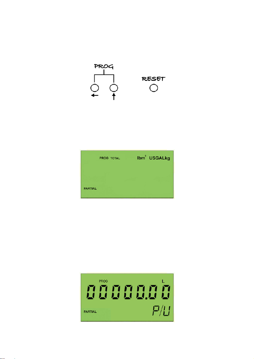
There are three push buttons with the following functions:
There are seven options of units: pounds (lb), cubic metres (m3), U.S. Gallons (USGAL), litres
(L), kilograms (kg), grams (g), and without specific units selected (all units off). The selected
unit will be flashing on the display (except when no specific units are selected). Use the push
button marked with the arrow pointing upwards to change from one unit to the next. By
pushing the two push buttons PROG at the same time (do not keep the push buttons
pushed) the selected unit will be saved into memory and the next programming screen for
the k factor will appear. If the RESET push button is pressed then the next programming
screen for the k factor will appear but the selected unit will not be saved into memory and
the previous measuring unit will be retained.
4.1.2 k factor (pulses per unit)
4.1 Programming
By pushing the two push buttons PROG at the same time for at least two seconds, the
display will change to the first stage of the programming mode.
4.1.1 Measuring Units
In this screen the measuring units can be programmed.

6
NOTE: During the programming process, the converter increases its power consumption. In
order to optimise the battery life, if during 30 seconds no push buttons are pressed, the
converter will return to the normal working mode. In this case the data in the memory will not
be changed.
4.2 Reset
The partial totalizer can be reset in two ways:
1) By pushing the RESET push button during two seconds the counter will be set to zero.
2) Without removing the plastic front cover by holding a magnet horizontally just below the
arrow pointing upwards for two seconds.
In this mode there are 7 digits (five whole numbers and two decimals). The value that must
be introduced is the pulses per unit factor given on the label of the COVOL or turbine.
Depending on the volume units, the k factor should be programmed as follows:
1) litres: the k factor will be directly the value on the flowmeter label.
2) m3: the k factor should be multiplied by 1000.
3) U.S. gallons: the k factor should be multiplied by 3.785.
To introduce the required values, pushing the push button marked with the arrow pointing
upwards, the blinking digit will increase. Once the desired value of the digit is achieved, by
pressing the push button marked with the arrow pointing left, the blinking digit will be the
next digit to be modified. On the seventh digit, by pressing this push button, the blinking digit
will return to the first digit.
When the k factor is programmed, by pushing the two push buttons PROG for at least 2
seconds, the value will be saved into memory and the instrument will return to normal working
mode. Again, if the RESET push button is pressed then the instrument will return to normal
working mode without making any changes in the k factor.
Magnet

7
4.3 Counter overflow
If one of the counters overflow, this condition is indicated at the right of the partial totalizer. If
none of the counters has overflowed then this part of the display is blank. When one of the
counters overflows then the display will show “A/B”, where “A” is the number of times that
the partial counter has overflowed and “B” is the number of times the total counter has
overflowed. The digit that indicates the number of times the counter has overflowed can be
effectively placed in front of the digits of the counter to give an extra digit. If a counter
overflows more than 9 times then the digit will be shown as “X”.
If the partial counter overflows and the total counter does not, and then the partial counter is
reset, the display will then go blank again. The overflow indication of the partial counter is
reset when this counter is reset.
In the above screen the total counter is shown as having overflowed once (this would be
equivalent to a count of 10002501) and the partial counter as having overflowed eight times
(this would be equivalent to a count of 810288).
5 MAINTENANCE
The battery has a life time of about 5 years. When the instrument detects that the battery
should be replaced, it shows a battery icon on the screen.
To change the battery, the plastic front cover must be removed. Then the battery, that is
situated below the push buttons, can be replaced.
After replacing the battery, it is not necessary to reprogram the pulse per litre factor of the
meter.
CR2450 batteries are easily found in the shops. If you prefer, we can change it in our factory.
6 EXAMPLE OF USEFUL CALCULATIONS
6.1 Measurement error correction
The calibration of the mechanical flowmeters is made with water at 20ºC. If a liquid of other
characteristics from the above specified is used, or for reasons of turbulences in the flow,
measurement errors can be induced.

8
To correct these types of errors we can modify the pulses per litre factor programmed in the
instrument.
Example - Shortage of volume
If we have a converter which specifies a k factor = 1.985, and when we check the volume of
a batch, we find that instead of having 100 litres as programmed, we have 105 litres (5%
more), we must apply the following correction:
Fk = k factor (original pulses per litre) = 1.985
V = Expected Volume = 100
Vr = Real Volume = 105
Fkn = New k factor = ? (1.887)
6.2 Change of units of measurement
In some cases we need to change the measurement units, for example, instead of working
in litres we need to work in kilograms. In this case we will need to know the density of the
liquid (ρ).
To change from litres to kg we must divide the pulse per litre factor by the density of the
liquid to obtain the new factor for programming the CIP II. For example, if the liquid has a
density of 0.9 kg/litre, the meter gives us 200 pulses per litre and we must count in kg, we
will program the CIP II using 222.222 as the new pulses per litre factor to be able to count
directly in kg.
Fk= Pulses per litre factor to count in kg
F = Original pulses per litre factor
ρ= Density of the liquid in kg/litre
7 TECHNICAL CHARACTERISTICS
Power supply
CR2450 lithium battery
Nominal voltage: 3 V
Capacity: 560 mAh
Power consumption: 8 µA
Totalizer counter
N. of digits: 7
Size of the digit: 8 mm
Reset: Cannot be reset
Partial counter
N. of digits: 5
Size of the digit: 6 mm
Reset: By means of push button or magnet
General characteristics
Ingress protection: IP65
Ambient temperature range: 0ºC … +60ºC
Battery life: More than 5 years

9
7.1 COVOL input characteristics
This input is designed for a potential free contact between terminals 1 & 2 of the connector.
Terminal 1 is connected to the common of the instrument. This input has a 1 M pull-up
resistor connected to terminal 1 and to the 3,3 V power supply. The input has a hysteresis
with the switching points situated at about 1 V & 2,1 V. If an open collector transistor is to be
used as the switching element instead of a COVOL, then the aforementioned parameters
must be taken into account.
Due to the presence of a filter to avoid the effects of contact bounce, the maximum pulse
frequency for the COVOL input is 300 Hz.
The minimum input frequency is 0.06 Hz
7.2 Turbine input characteristics
The turbine input is designed for connecting to the coil of a magnetic pick-up.
The input impedance is 1,2 kΩ. This input is protected to limit the maximum applied voltage
to the circuit. This protection consists of two diodes in parallel and two 100 Ohm resistors.
The maximum voltage that can be applied to the input is 10 Vpp. Voltages higher that this
can cause damage to the equipment.
The maximum input frequency is 5000 Hz.
The minimum input frequency is 0.06 Hz.
The minimum input voltage is 7mVpp.

10
8 SAFETY INSTRUCTIONS
The series CIP II of programmable totalizers are in conformity with all
essential requirements of all EC directives applicable to them:
2014/30/EU Electromagnetic compatibility directive (EMC)
2012/19/EU Waste electric and electronic equipment directive
(WEEE).
2011/65/EU Directive relating restriction of the use of certain
hazardous substances in electrical and electronic
equipment (ROHS).
Equipment for hazardous areas:
2014/34/EU Directive relating equipment and protective systems
intended for use in potentially explosive
atmospheres (ATEX).
Declarations of conformity EC can be downloaded from the section “Downloads” of the
Tecfluid S.A. website. www.tecfluid.com
8.1 Certificate of conformity TR CU (EAC marking)
Tecfluid S.A. have subjected the series CIP II of programmable
totalizers to a certification procedure according to the technical
regulations of the Customs Union of the Eurasian Economic Union
(EEU).
This Certificate is an official document confirming the quality of production with the
standards on the territory of the Customs Union, particularly regarding safety requirements
and electromagnetic compatibility.
9 ADDITIONAL INSTRUCTIONS FOR THE ATEX VERSION
This chapter only applies to equipment intended for use in explosive atmospheres.
9.1 Flameproof enclosure
These equipment conform with the directive 2014/34/EU (Equipment and protective systems
intended for use in potentially explosive atmospheres) as indicated in the EC-type
examination certificate LOM 14ATEX2006 X, LOM 14ATEX2008 X and its marking.
Given that this instrument belong to group II, it is intended for use in places likely to become
endangered by explosive atmospheres, but not in mines.
The category is 2GD, that is, it is intended for use in areas in which explosive atmospheres
caused by mixtures of air and gases, vapours, mists or air/dust mixtures are likely to occur.
9.1.1 Surface temperature
Equipment is certificated as Exd IIC T6.
The maximum possible surface temperature is 85ºC.
WARNING: RISK OF IMPACT
Because the housing is made of aluminium, the equipment must be installed and
operated always in locations at low risk of impact.
11
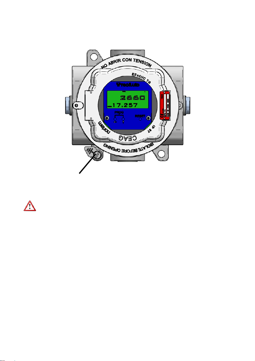
9.1.2 Connecting conductive parts to earth
When the instrument is not grounded securely through the connection process, it should be
grounded through the housing screw, as shown in the figure.
9.1.3 Maintenance
NOTE: The cover should never be opened in presence of explosive atmosphere.
There is no special maintenance for the ATEX version.
9.1.4 Technical characteristics of the ATEX version
They are the same as in the section 7.
Grounding screw
12
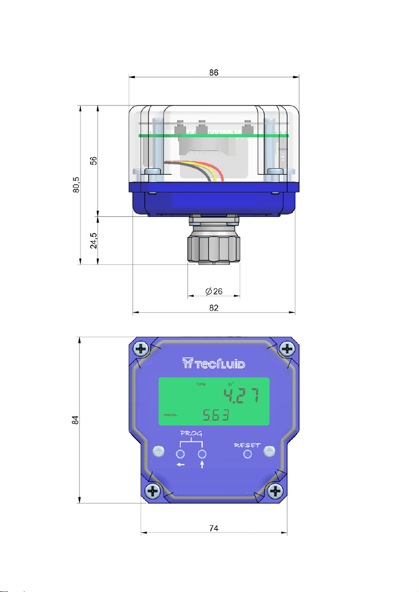
Local CIP II
10 DIMENSIONS
All dimensions in mm
13
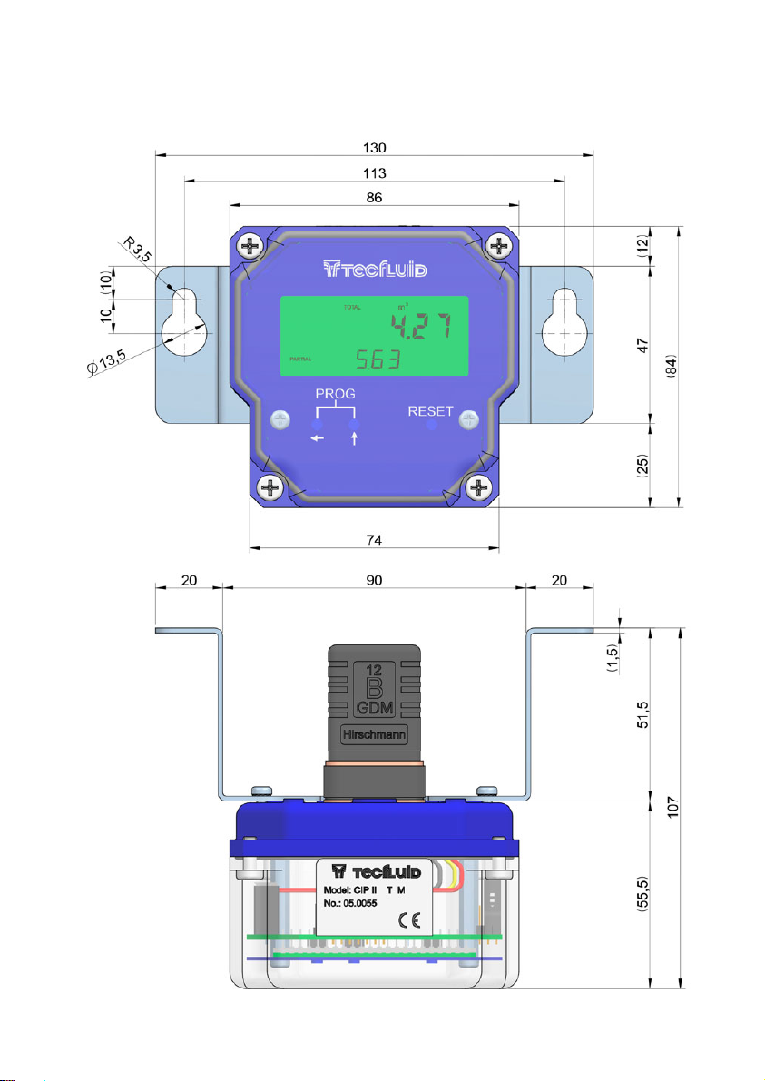
Remote CIP II
All dimensions in mm

14
WARRANTY
Tecfluid S.A. guarantee all the products for a period of 24 months from their sale, against all faulty
materials, manufacturing or performance. This warranty does not cover failures which might be
imputed to misuse, use in an application different to that specified in the order, the result of service or
modification carried out by personnel not authorized by Tecfluid S.A., wrong handling or accident.
This warranty is limited to cover the replacement or repair of the defective parts which have not
damaged due to misuse, being excluded all responsibility due to any other damage or the effects of
wear caused by the normal use of the devices.
Any consignment of devices for repair must observe a procedure which can be consulted in the
website www.tecfluid.com, “After-Sales” section.
All materials sent to our factory must be correctly packaged, clean and completely exempt of any
liquid, grease or toxic substances.
The devices sent for repair must enclose the corresponding form, which can be filled in via website
from the same “After-Sales” section.
Warranty for repaired or replaced components applies 6 months from repair or replacement date.
Anyway, the warranty period will last at least until the initial supply warranty period is over.
TRANSPORTATION
All consignments from the Buyer to the Seller´s installations for their credit, repair or replacement must
always be done at freight cost paid unless previous agreement.
The Seller will not accept any responsibility for possible damages caused on the devices during
transportation.
Tecfluid S.A.
Narcís Monturiol 33
08960 Sant Just Desvern
Barcelona
Tel: +34 93 372 45 11
Fax: +34 93 473 44 49
tecfluid@tecfluid.com
www.tecfluid.com
The technical data described in this manual is subject to modification without notification if the technical innovations in the
manufacturing processes so require.
Quality Management System ISO 9001 certified by
Pressure Equipment Directive certified by
ATEX European Directive certified by
This manual suits for next models
1
Table of contents
Other Tecfluid Media Converter manuals


