Klimawent BIG-12000/Ex User manual

EN
USE AND MAINTENANCE MANUAL
Filtering unit BIG-12000/Ex
(KOMPAC AIR 325 4x4 12000)
ATEX marking:
II 3 D Ex tD A22 T200ºC
Contents:
INTRODUCTION .........................................................................................................................................................2
PURPOSE ...................................................................................................................................................................2
RESERVATIONS OF MANUFACTURER..................................................................................................................3
TECHNICAL DATA.....................................................................................................................................................3
STRUCTURE ADN FUNCTION.................................................................................................................................4
ASSEMBLY AND STARTUP .....................................................................................................................................5
OPERATIONAL USE..................................................................................................................................................8
TROUBLESHOOTING GUIDE..................................................................................................................................14
MAINTENANCE AND REPAIR................................................................................................................................14
OCCUPATIONAL HEALTH AND SAFETY..............................................................................................................15
TRANSPORT AND STORAGE...............................................................................................................................15
TERMS OF WARRANTY.........................................................................................................................................16
DECLARATION OF CONFORMITY ........................................................................................................................16
10.10.2019
Producer: KLIMAWENT S.A.
81-571 Gdynia, ul. Chwaszczyńska 194
tel. 58 629 64 80, 58 771 43 40
fax 58 629 64 19
email: klimawent@klimawent.com.pl
www.klimawent.com.pl
issue: October 2019

Klimawent –the warranty of highest quality at attractive price
2 z 16
Filtering unit BIG-12000/Ex
10.10.2019
INTRODUCTION
The purpose of the present Use and Maintenance Manual is to supply User with directions within the range of
application, assembly, start-up and operational use of the BIG-12000/Ex Filtering unit.
Prior to assembly at the place of operation and use, it is important to get thoroughly acquain-
ted with the contents of the present instruction.
With regard to continuity of work carried on improvement of our products, we reserve for
ourselves the revision possibility of the draft and technological changes improving their
functional features and safety.
Construction of BIG-12000/Ex meets the requirements of the current state of technology as well as the safety and
health assurances included in:
the safety and health assurances included in:
2006/42/EC Directive of the European Parliament and of the Council of the 17 May, 2006 on machinery,
amending the 95/16/EC Directive (recast) / Official Journal EC L157 of the 09.06.2006, page 24);
2014/35/EC Directive of the European Parliament and of the Council of the 26 February, 2014 on the harmo-
nisation of the laws of the Member States, relating to the making available on the market of electrical equipment
designed for use within certain voltage limits / Official Journal EC L96 of the 29.03.2014;
2014/34/EC Directive of the European Parliament and of the Council of the 26 February, 2014 on the harmo-
nisation of the laws of the Member States, relating to the equipment and protective systems intended for use in
potentially explosive atmospheres / Official Journal EC L96 of the 29.03.2014 /
1999/92/EC Directive of the Council of the 19 December, 1999 on minimum requirements regarding safety
of health protection of workers employed at workplaces where explosive atmosphere is likely to occur / Official
Journal No.138, Pos. 931/
Is in accordance with the subsequent harmonised standards:
EN ISO-12100:2012 Safety of machinery –General principles of design –Assessment and reduction of hazard
EN 60204-1:2018-12 Safety of machinery –Electrical equipment of machines –Part 1: General requirements
EN ISO 13857:2010 Safety of machinery –Safe distances to prevent hazard zones from being reached by up-
per and lower limbs
EN 60079-0:2013-03/A11:2014-03 Electrical appliances in areas of gas explosion hazard - Part 0: General
requirements
EN 1127-1:2011 Explosive atmospheres –Explosion prevention and protection. Basic terminology and me-
thodology
EN ISO 80079-36:2016-07 Explosive atmospheres –Part 36: Non-electrical appliances in areas of explosion risk
Methodology and requirements
PURPOSE
BIG-12000/Ex is appropriate for cleaning the dust laden air from dry dust particles, arising during production
processes with occurrence of powdery materials and dust particles of ST1 explosiveness class. The appliance is
equipped with 16 cartridge filters, with antistatic polyester membrane –functioning on the basis of surface filtration.
Admissible maximum temperature of the filtered air is 40ºC.
The device can be applied for such processes as:
–
grinding of non-sparking materials,
–
sand blasting, shot peening,
–
mechanical cutting of metals, gas-, plasma-, laser-, arc cutting of metals,
–
polishing, planishing,
–
processing of plastics,
–
metalization,
–
powder varnishing.
Basic advantages of the device are optimum filtration efficiency, long operational use (longevity) of the cartridge
filters, low power consumption and simple and fast maintenance. The appliance is admitted for use, according to
the Ex marking, for cleaning the air in areas of explosion hazard, according to the ATEX 137 1999/92/EC Directive.
According to ATEX, the operational conditions are specified (as for this device) as follows:
Ex II 3 D Ex tD A22 T200ºC. The subsequent markings are interpreted as:
group II –the device is designed for work in enterprises, in on-ground premises, in sites of occur-
rence of explosion atmospheres, except for application in areas of methane hazard (firedamp), or risk
connected with carbon dust;
category 3 –the device is designed for application in areas where explosive atmospheres are likely
to occur, whereby the explosive atmospheres are of low risk;
D hazard –flammable dusts;
Ex tD A22 IP65 –application of the implemented motor –as constructed and tested according to the
European standards for application in areas of explosion hazard, with dust-proof housing and with
the implemented protection against humidity.
T200ºC –the surface temperature of any part (of the device)will not exceed 200ºC during normal
operation.

Klimawent –the warranty of highest quality at attractive price
10.10.2019
Filtering unit BIG-12000/Ex
3 z 16
BIG-12000-Ex filtering unit can be installed, exclusively in areas classified as 22, or in areas not featuring
explosive hazard.According to the ATEX 137 Directive, User has to determine the environment where
the appliance shall be used.
RESERVATIONS OF MANUFACTURER
3.1 Manufacturer is not responsible for damages / malfunctions being caused as a result of reasons
mentioned below:
Any consequences following from the installing that is in contradiction to the present Use and Maintenance
Manual.
Situations where the appliance is connected to the electrical power supply- or the pneumatic system
incorrectly.
Operational use that is in contradiction with the present Use and Maintenance Manual and its specified
purpose.
Installing of any additional elements that are not belonging to the normal device structure (or accessory
set) is not acceptable.
Introduction of any structural or constructional modifications of the system on one’s own.
Situations when the principles of control and maintenance of the appliance are not observed.
Forwarding of the air containing viscous and aggressive impurities or of the air temperature exceeds 40C
what might result in damage of the filters.
3.2
In the course of operational use, it is important to prevent ignition sources (i.e. sparks, cigarette
butts / embers) from getting into the filtering unit.
3.3
Operator should wear antistatic clothes while emptying the waste container, during the technical
inspection, maintenance and during any other activities near the filtering unit.
3.4
Do not use mobile phones and devices emitting electromagnetic waves close to the filtering unit
and in the vicinity.
3.5
At the side of decompression panel –it is important to create a hazard area of potential explosion
according to the Fig. No.5. This area should be free of barriers such as machines, devices, walls
etc.
3.6
In case when explosion hazard exists within the whole installation, (where the filtering unit is
installed), User should carry out the total risk evaluation, with reference to the being valid
regulations and should apply protections of the filtering unit and the fan.
TECHNICAL DATA
Table No.1
Type
Maximum
volume flow
Maxi-
mum
vacuum
Motor
rate
Cell
feeder
Supply
voltage
Quantity of
cartridge
filters
Compressed
air
consumption
Weight
[m³/h]
[Pa]
[kW]
[kW]
[V/Hz]
[pcs]
[NI/activ]
[kg]
BIG-12000/Ex
12000
5000
15
0,55
3x400/50
16
347
1885
Filtration efficiency 99,9% (according to the BIA classification) the filters carry the USGC class certificate
Cartridge filters: quantity 16 pieces;
diameter 325 mm
height 1200 mm
total filtration area 233-302 m2 for 175 pleats of the cartridge filters
According to the 99/92/EC ATEX 137 Directive, manufacturer
carried out the classification of the internal and external zones,
connected with the explosion hazard during the operation
of the filtering unit.
In the Fig. No.1 is presented the classification of the internal
zones. The chamber of filters and the hopper chamber along
with the waste container have been specified as zone 20/21,
because in these areas always and in long periods potentially
explosive atmosphere occurs.
Whereas, the regeneration chamber is classified as zone 22,
because the dust occurs in this area sporadically, in case of
failures consisting in damage of the cartridge filter or the filter
mounting.
External zones can be created:
while opening the inspection doors,
during the emptying the waste container.
They have been classified as zone 22.
Fig. No.1 –Classification ATEX –internal zones

Klimawent –the warranty of highest quality at attractive price
4 z 16
Filtering unit BIG-12000/Ex
10.10.2019
STRUCTURE ADN FUNCTION
5.1 Structure
BIG-12000/Ex filtering unit consists of three functional assemblies:
Regeneration chamber, being the upper part of the device, where are located outlets from the cartridge filters and
Venturi Orifices. Outside the regeneration chamber is installed the compressed air installation, consisting of:
–
compressed air tank –constructed for operational pressure not exceeding 0,8 MPa, the tank meets the re-
quirements of the European Union Directive 87/404/EEG and 90/488/EEG;
–
four electromagnetic valves of diameter 1”½, designed for regeneration of the cartridge filters, these valves
meet the requirements of directives: ATEX 94/9/EC and EMC 2014/30/EC;
Chamber of filters –forms the middle part of the filtering unit and contains the cartridge filters. On the chamber
housing is located the inspection door, (for filter replacement) and a decompression panel lowering the pressure
in case of potential explosion. Outside the chamber is installed a micro-controller –to activate the electromagnetic
valves, (described in details in Section 7);
Supporting construction along with the hopper chamber. Underneath the hopper chamber is placed a self-loading
funnel for dust / waste and a cell feeder –providing a continuous dust discharging and its loading into the transport
container or into the discharge ducting. Discharge of the accumulated dust ought to be carried out by operator.
Fig. No.2 –BIG-12000-/Ex –Structure and dimensions
BIG-12000/Ex filtering unit is served by an Ex execution fan (as additional equipment upon separate order). To
control the device is applied a switchgear, which should be installed outside (beyond)the zone of
explosion hazard. Detailed description can be found in Section 7 of the present Use and Maintenance Manual.
CAUTION:The switchgear is delivered upon separate order.
5.2 Function
BIG-12000/Ex filtering unit provides separation of the air containing dry dust fraction. The dust laden air is guided
to the chamber of filters. Here, in the decompression process and because of the flow velocity reduction, larger
particles of dust are extracted into the hopper chamber, and subsequently they fall into the waste container.

Klimawent –the warranty of highest quality at attractive price
10.10.2019
Filtering unit BIG-12000/Ex
5 z 16
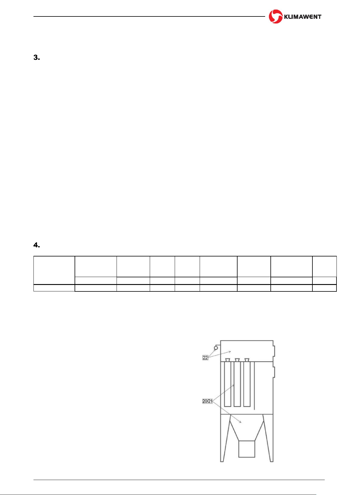
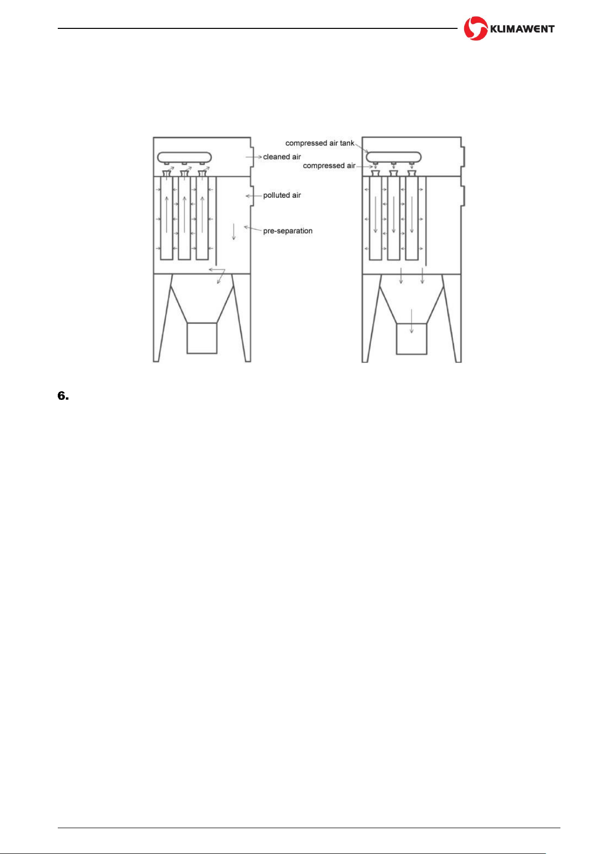
Precise dust cleaning proceeds while the air flows through the cartridge filters. In the Fig. No.3 is presented a run
diagram of the air flow through the filtering unit. As the dust accumulates on the operational surface of the cartridge
filters, this reduces the air flow intensity. To limit this disturbance, the device is equipped with a continuous
regeneration system of the filters. The impulses of compressed air (directed into the cartridge filters) strike off the
dust particles. The cleaning air is supplied from the compressed air tank, through the electromagnetic valves that
are operated by the micro-controller (as in details described in Section No.7).
In the Fig. No.4 is illustrated a schematic diagram of regeneration of the cartridge filters.
Fig. No.3 Filtration scheme Fig. No.4 Scheme of filters regeneration
ASSEMBLY AND STARTUP
6.1 Description of mounting
Before the assembly of the device in the place of use, check if the device is complete, and if it is not damaged, or
there are indentations, etc. The appliance is delivered in two assemblies, so it should be installed by means of
adequate lifting devices and by a specialised assembly team.
First, put the supporting structure with the hopper chamber. The supporting frame should be levelled and its legs
fastened firmly to the floor. Having installed the first assembly, put the chamber of filters (with the fixed to it
regeneration chamber) on it. Handle with care, as the assembly is of large dimensions. At the upper part of the
regeneration chamber are installed lifting hooks (for lifting and positioning during the transport and assembly
activities).
After the chamber of filters is connected with the supporting structure, seal up the join surface with “silicone” and
screw it up thoroughly with bolts. The screws, bolts and “silicone” are delivered by manufacturer along with the
device.
The compressed air tank and the electromagnetic valves are delivered to the operator in completely assembled
state. Having installed the device, connect it to the external compressed air installation of 0,6 0,8 MPa. The
pressure air must not contain pollutants, oil and humidity.
The connection must be equipped with a cut-off valve, air filter and a dewaterer. These elements are not
delivered along with the device. The nominal diameter of the compressed air connection (for the device of 16
cartridge filters and at the nominal diameter of the compressed air tank of 8”) should be 1”1/2.
6.2 Start-up
Upon first operation of the compressed air installation (of the device), check if the connected part of the
compressed air system is sufficiently cleaned of the metal particles, raspings, rust, etc., because the membrane
of the electromagnetic valves would get damaged. If in the first stage of start-up there is not enough air flow
intensity (in the system) –this means the valves are not tight enough. Shut the cut-off valve in the supply of the
compressed air tank. Wait until the air pressure in the system reaches 0,6 0,8 MPa, and then quickly open the
cut-off valve.
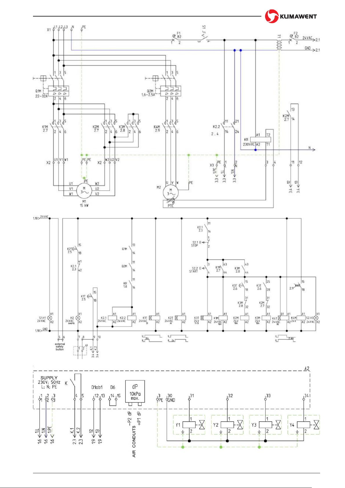
Connect the electrical system, power supply and the control units –strictly according to the enclosed Connection
Diagram Fig. No.6, 7 and 8. As the control system is very complicated, any activity of device connection/energizing
must be carried out by an authorised installing team with qualifications. The filtering unit and the fan should be
connected to the equilibrating grounding profile.
Connect the motor with reference to the adequate data placed on the nominal data plate and in conformity with
the Connection Diagram on the cover of the terminal box (fastened to the motor).
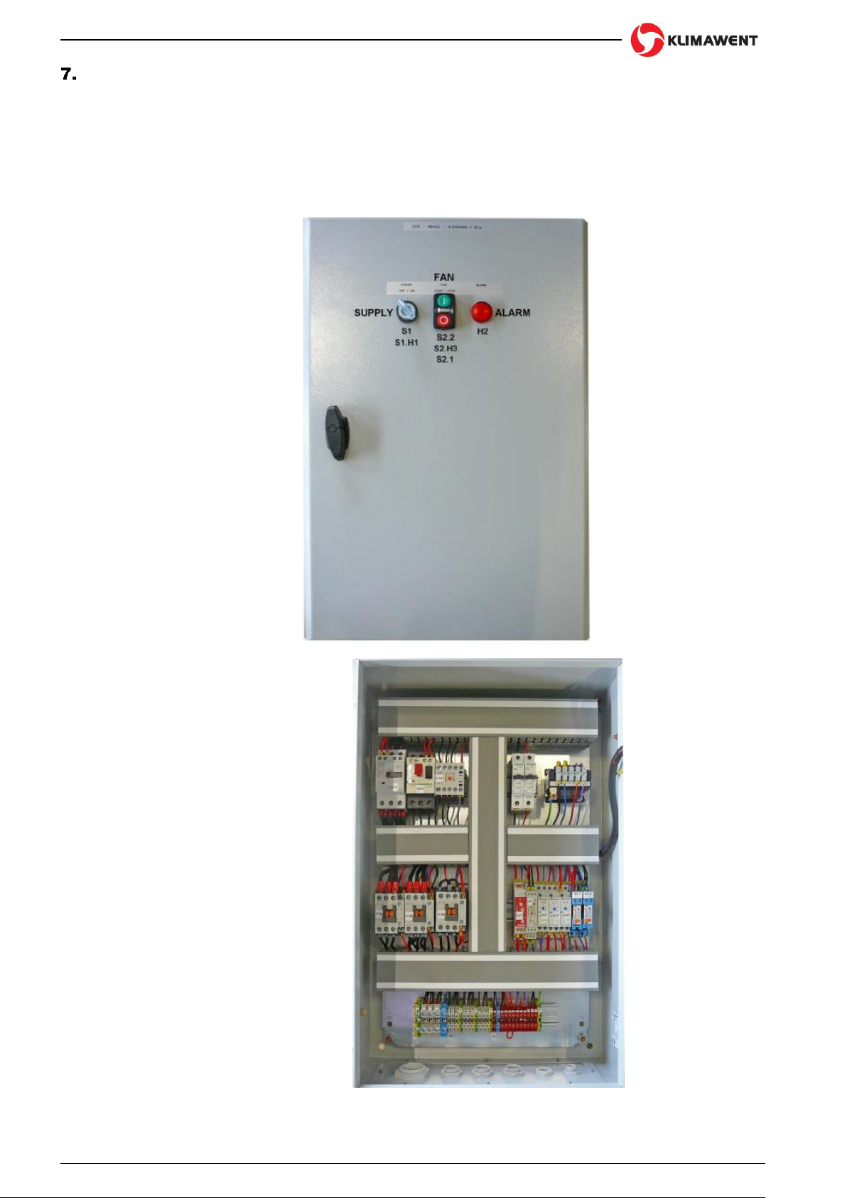
Switchgear A1 should be mounted in area, beyond the explosion hazard zone.

Klimawent –the warranty of highest quality at attractive price
6 z 16
Filtering unit BIG-12000/Ex
10.10.2019
6.3 ATEX Directive
BIG-12000/Ex filtering unit has been classified, according to the 2014/34/Ex Directive and therefore, it is
important to take precaution measures during the installing and start-up, and follow subsequent aspects:
As the filtering unit is of Category 3D, it should be installed according to the PN-EN 60079-0:2013,
PN-EN 1127-1:2011, PN-EN 13463-1:2010 standards, therefore the installer must be thoroughly ac-
quainted with the contents of these standards.
Installer should know the ATEX Classification of installing zones, as well as the hazard connected
with the atmosphere of explosion risk. Especially, here is important the hazard of explosion, of fire,
with the purpose of selection of suitable protection sorts.
Any activities, related to the installing, necessarily must be performed by a specialised assembly team
(after being instructed).
Having completed the assembly, check the conductivity between the subsequent parts of the device,
and check if the maximum resistance does not exceed 106Ohm.
Grounding of the device and of its parts should be carried out and examined by an authorised person,
according to being in force regulations (in this range).
Any device modification / change, within the construction and mounting, without the consent of
deliverer shall cause the invalidation of conformity with requirements of ATEX Directive.
6.4 Precautions measures
Check if the lifting devices are suitable, approved for use and used by authorized operators;
During the activity of displacement and assembly –it is important to point out the hazardous zones, that no
other people in the vicinity (incidental workers) would enter these zones;
Transport, assembly and start-up should be executed exclusively by authorized employees, who have been
instructed properly and approved by User;
Prior to any activities connected with mounting and start-up, it is important to get acquainted with the contents
of the present Use and Maintenance Manual.
Fig. No.5 –Decompression panel –Zone of hazard

Klimawent –the warranty of highest quality at attractive price
10.10.2019
Filtering unit BIG-12000/Ex
7 z 16
Fig. No.6 –Connection Diagram 1/3
Fig. No.7 –Connection Diagram 2/3
Fig. No.8 –Connection Diagram 3/3

Klimawent –the warranty of highest quality at attractive price
8 z 16
Filtering unit BIG-12000/Ex
10.10.2019
OPERATIONAL USE
The filtering unit is designed for filtration of the air, at the workplaces, according to the purpose of application as
described in Section 2 of the present Use and Maintenance Manual.
7.1 Description of the control system
Control unit is designed to operate the filtering unit, providing automatic regeneration of surfaces of the filters, by
means of cyclical impulses of compressed air. The control system consists of subsequent assemblies: switchgear
A1, micro-controller A2 and aterminal box A3. In the housing of the switchgear A1 are included electrical elements
providing the appropriate and safe work of the whole filtering unit.
Power supply 3x400 ±10%; 50Hz ±1%; L1; L2; L3; N; PE.
Fig. No.9 –Switchgear –Cover
Fig. No.10 –Switchgear –internal view

Klimawent –the warranty of highest quality at attractive price
10.10.2019
Filtering unit BIG-12000/Ex
9 z 16
Micro-controller A2 provides control of the electromagnetic valves –the function is described in Section 7.2.
Supply 230V ±10%; 50Hz ±1%; L; N; PE
Fig. No.13 –Decompression panels
The A3 terminal box connects the cable to the sensors on the venting panel, with the output cable, (going out of
the Switchgear A1). When the cable on the panel is interrupted (during the explosion), the device automation
disconnects the fan and the system of regeneration of filters. The cell feeder is of Ex execution and is equipped
with a PTC sensor that protects the motor from overheating.
ATEX marking of Ex features:
II 3D Ex tc IIIC IP T100ºC
7.2 Use of the A2 micro-controller

Klimawent –the warranty of highest quality at attractive price
10 z 16
Filtering unit BIG-12000/Ex
10.10.2019

Klimawent –the warranty of highest quality at attractive price
10.10.2019
Filtering unit BIG-12000/Ex
11 z 16

Klimawent –the warranty of highest quality at attractive price
12 z 16
Filtering unit BIG-12000/Ex
10.10.2019

Klimawent –the warranty of highest quality at attractive price
10.10.2019
Filtering unit BIG-12000/Ex
13 z 16
7.3 Startup of the system
Switch on motor switches Q1M, Q2M and the protections in the switchgear A1.
Check if the F1 fuse in the micro-controller is not damaged.
Apply the supply voltage (by means of the S1 disconnector) to the control system. This will be indicated by
the white S1.H1. lamp
Now, the fan can be safely switched on with the S3.2 button –under the condition that the red lamp ALARM
(on the switchgear door) in not on.
When the green lamp (built in the double button S3) is lighting –this is the information that the fan is in
operation and the filter regeneration system is switched on; {To make sure, that the filter regeneration system
is functioning –after the first device startup, examine the device, check (after the ALARM state emerges) the
communicates emerging on the micro-controller display}. Additionally, after the first start-up, check the
rotation sense of the fan impeller.
To switch off the fan –press the red button S3.1.
The green lamp (build in the button) goes off –subsequently, proceeds the final filters regeneration –at any
time the fan can be started again.
7.4 Alarms
In the device can appear states of alarms, caused by:
activation of the disconnectors (2),
interruption of the sensors (3 pieces),
alarm from the micro-controller (controlling the function of the electromagnetic valves) –description in 7.2.
These alarms are signalised by the red lamp H2 (placed on the door of the switchgear A1). When the alarm
occurs, it is important to disconnect the power supply, find the failure/damage, find out its/their reason and
remove the malfunction. After the failure is removed correctly, and the power supply is applied again –the filtering
unit can be operated again.
CAUTION: If the fan works incorrectly, please contact the Deliverer.
7.5 Removal of dust
In the course of operational use, the dust is continuously removed from the hopper funnel by means of the cell
feeder. The way of dust/waste transporting from the funnel (and its disposal) is depended on the decision of
operator. Within this range –observe the instructions and regulations in the 1999/92/EC Directive of the European
Parliament and the Council of the December 16, 1999 on minimum requirements for safety and health protection
of the workers employed at workplaces –where explosive atmosphere is likely to occur (Official Journal EC L 137
of 07.06.2000). Moreover, it is important to strictly observe the PN-EN 1127-1:2011 standard –Explosive
atmospheres –Explosion prevention and protection. Basic terminology and protection.
7.6 Measures of precautions during the maintenance
The filtering unit must be used according to the present Use and Maintenance Manual and according to the
being in force regulations.
Maintenance steps / activities should be executed by authorised workers after the instructions.

Klimawent –the warranty of highest quality at attractive price
14 z 16
Filtering unit BIG-12000/Ex
10.10.2019
In the course of operational use, be careful that no ignition sources (e.g. sparks, cigarette butts, embers)
gets into the device.
During the emptying of the waste container and during any other activity near the filtering unit, it is important
to wear antistatic clothes. Put the antistatic pad/rug underneath the waste container.
Directly, at the filtering unit, and in the vicinity –do not use mobile phones and other devices emitting
electromagnetic waves.
TROUBLESHOOTING GUIDE
Table No.2
Problem
Possible reason
Corrective action
1.
Dust is emerging outside the
device
The cartridge filter got released in its
Replace the faulty cartridge filter
mountings or go damaged
or correct its mountings.
The sort of dust is another than it is
Contact the manufacturer
foreseen in the instructions
Low filtration efficiency
Contact the manufacturer
2.
Dust is emerging outside the
The cartridge filter is faulty
Replace the faulty element
device after a longer period
The flange of the mounting of the
Replace the faulty element
of operational use
cartridge filter got damaged
3.
Low pressure of the compressed air
Adjust to obtain the pressure of
therefore the regeneration is inefficient
0,60,8 MPa in the system
The cleaning time and work time
Adjust the work of micro-controller
are not adjusted correctly
according to the present Use and
Air flow efficiency decreased
Maintanance Manual
after a period of correct function
Too high humidity of the filters, cau-
It is important to dewater the com-
sed by the humid air in the compres-
pressed air tank, check the state
sed air system
of the compressed air system
Dust emerges in another area, due to
Limit the temperature at the inlet
temperature higher than 40C of the
inlet air
CAUTION: The states of ALARM during the function are described in Section 7 “OPERATIONAL USE”.
MAINTENANCE AND REPAIR
9.1 Cartridge filters
It is necessary to undertake a visual control of the cartridge filters, at any case when the waste container
(underneath the hopper chamber) is emptied of the dust. The check must be carried out through the revision door
–examine if the mounting elements are installed correctly, check the state of the filtration surfaces, the degree of
pollution. Additionally, check if there are any damaged elements, etc.
Additionally, technical revision must be carried out –when the device functions incorrectly, in overall. In case
when any cartridge filters are worn out or damaged –replace them for new. First release the mounting nuts, turn
the cartridge filter itself and take it out.
9.2 Fan
Technical revision and maintenance of the fan should be executed according to the instruction of the fan. In case
when faulty function of the fan is noticed, please contact the fan producer.
9.3 Compressed air tank.
The compressed air tank must be submit to technical revision and maintenance, according to the valid regulation
on the pressure devices. Periodically, examine all the connections on the compressed air tank. It is important to
dewater the tank, through the connection (installed in the lower part of the tank).
9.4 Electromagnetic valves
Electromagnetic valves do not require current maintenance. Simply, it is sufficient to check the electrical
connections, the state of grounding and tightness on the pneumatic installation. It is recommended to replace the
valves after 2 years of use, and not later than after 4 years of operational use (but in this case, contact the
producer of the filtering unit).
9.5 Recommended periods of technical revisions and maintenance of the filtering unit.
Table No.3
Current revision
Systematic cleaning of the device and its assemblies,
in order to avoid accumulating of the dust layer ex-
ceeding 5 mm
Every 6 8 months –in the device with the cell feeder
Control visually the cartridge filters, through the revi-
sion door.

Klimawent –the warranty of highest quality at attractive price
10.10.2019
Filtering unit BIG-12000/Ex
15 z 16
Once for 2 3 months
Overall visual control of the supporting construction
(base frame) and of the housing. Examine the screw
connections and anti-corrosion protection.
Once for 12 months
Check the state of the electrical connections and of the
external installation of the compressed air, check the
connections of the electromagnetic valves.
Once for 12 18 months
Visual control of the compressed air tank and of its
dewaterer. When, (with reference to the environment
and the state of the pressure air), it is necessary –this
revision should be executed more frequently.
Fan –Use and Maintenance Manual of the fan
Follow as according to the instruction
Motor –Use and Maintenance Manual of the of the motor
Follow as according to the instruction
9.6 Measures of precaution during the revision activities and the maintenance
Maintenance and revision ought to be executed with reference to the being valid regulations, and
with the present Use and Maintenance Manual and carried out by authorised workers after being
instructed.
Any activities on the device must be carried out after the fan is switched off and disconnected from
the power supply mains.
During these activities it is important to wear antistatic clothes.
While emptying the waste container of the dust, during the dismantling of the container and its
mounting –the waste container must be placed on the antistatic pad / rug.
Near the device, do not use mobile phone, and other devices emitting electromagnetic waves.
The filtering unit cannot be submit to modification or complemented with functional parts or control
elements, without the consent of the Deliverer.
OCCUPATIONAL HEALTH AND SAFETY
Assembly, installing, start-up and maintenance can be carried out after getting acquainted with the
contents of the present Use and Maintenance Manual.
For safety reasons, the device must be connected to the power supply system –strictly according
to the enclosed Connection Diagram, and with the being in force regulations within the range of
personal protection against electric shock.
Connection to the power supply system should be executed by an authorised person with electrical
qualifications.
Maximum operational pressure of the compressed air, for safety reasons, must not exceed 0,8 MPa.
Any activities, connected with repair and technical revisions as well as emptying the filled up waste
containers (underneath the hopper chamber) –should be executed after the fan is switched off and
the device disconnected from the power supply.
The fan as a rotating appliance –constitute a potential source of hazard, therefore installing, start up
and maintenance should be carried out by qualified personnel.
As the filtering unit is equipped with a decompression panel VMP 450x800 (0,34m2) –the whole device
should be placed in such a way, that there is provided free access to the control system, and
additionally, (in case of explosion) there should be safety area for the discarded vent panel. During
the explosion, the control connection shall be interrupted and the filtering unit stops functioning.
TRANSPORT AND STORAGE
The filtration body (along with the cartridge filters) and the regeneration chamber with the compressed air tank
and electromagnetic valves are integrated together with screw connections. The second assembly is the self-
discharging hopper with the supporting structure.
BIG-12000/Ex filtering unit is transported in two assemblies, wrapped in foil, placed on transport pallets. During
the time of transport, the assemblies must be located vertically and protected from overturn (being knocked down)
and from displacement.
Handle with care during the lifting the subsequent assemblies, during the transport, unloading and mounting. The
device has to be stored in close rooms and in dry rooms and in areas of efficient ventilation.

Klimawent –the warranty of highest quality at attractive price
16 z 16
Filtering unit BIG-12000/Ex
10.10.2019
TERMS OF WARRANTY
The period of warranty for the purchased device is indicated in the Card of Warranty. The warranty does
not comprise:
●
mechanical damage and malfunctions caused by User,
●
device failures caused during the use which is in contradiction with the purpose of application and with the
present Use and Maintenance Manual,
●
malfunctions resulting from the improper transport, storage or incorrect maintenance.
Infringement of the Section 3 “Reservations of Producer” of the present Use and Maintenance Manual and,
especially modifications undertaken by User on one’s own or use in contradiction with the purpose of application
–shall result in the loss of warranty validity.
DECLARATION OF CONFORMITY
DECLARATION OF CONFORMITY EC No. _______________
Manufacturer (eventually also the authorised representative / importer):
name: KLIMAWENT S.A.
address: 81-571 GDYNIA, ul. Chwaszczyńska 194
A person, authorised for issuing the technical documentation:
name and address: Teodor Świrbutowicz, KLIMAWENT S.A.
hereby declares that the product:
Filtering unit
type / model:
BIG-12000/Ex
serial number:___________________
year of production: ___________________
Meets the requirements of the subsequent European Directives:
2006/42/EC Directive of the European Parliament and of the Council of the 17 May, 2006 on machinery,
amending the 95/16/EC Directive (recast) / Official Journal EC L157 of the 09.06.2006, page 24);
2014/35/EC Directive of the European Parliament and of the Council of the 26 February, 2014 on the harmo-
nisation of the laws of the Member States, relating to the making available on the market of electrical equipment
designed for use within certain voltage limits / Official Journal EC L96 of the 29.03.2014;
2014/34/EC Directive of the European Parliament and of the Council of the 26 February, 2014 on the harmo-
nisation of the laws of the Member States, relating to the equipment and protective systems intended for use in
potentially explosive atmospheres / Official Journal EC L96 of the 29.03.2014 /
1999/92/EC Directive of the Council of the 19 December, 1999 on minimum requirements regarding safety of
health protection of workers employed at workplaces where explosive atmosphere is likely to occur / Official
Journal No.138, Pos. 931/
is in accordance with the requirements of the following harmonised standards:
EN ISO-12100:2012 Safety of machinery –General principles of design –Assessment and reduction of hazard
EN 60204-1:2010 Safety of machinery –Electrical equipment of machines –Part 1: General requirements
EN ISO 13857:2010 Safety of machinery –Safe distances to prevent hazard zones from being reached by
up-per and lower limbs
EN 60079-0:2013-03/A11:2014-03 Electrical appliances in areas of gas explosion hazard - Part 0: General
requirements
EN 1127-1:2011 Explosive atmospheres –Explosion prevention and protection. Basic terminology and
methodology
EN ISO 80079-36:2016-07 Explosive atmospheres –Part 36: Non-electrical appliances in areas of explosion
risk Methodology and requirements
place, date
signature of the
authorised person
name, surname,
function of the signatory
Table of contents
Other Klimawent Air Cleaner manuals