Klipspringer LAQUAtwin User manual

User Manual
LAQUAtwin Conductivity Meters
Product Code: PQ0011, PQ0012, PQ0013
01473 461800
service@klipspringer.com
www.klipspringer.com

UNCONTROLLED IF PRINTED
PAGE(S) 1 OF
7
Part Names
Measurement cell
Protection cover
Lithium batteries
MEAS switch
ON/OFF switch
CAL switch
Waterproof gasket
Strap eyelet
Note: Press the switches 0.5 seconds or more unless otherwise specified.
Initial Setup
Attaching the sensor:
1. Power OFF the meter.
2. Confirm that the waterproofing gasket is clean and undamaged.
3. Slide the sensor onto the meter so that catch "A" on the back of the
meter fits into hole "a" on the sensor tongue as shown.
Note: Be careful not to twist the waterproof gasket.
Detaching the sensor:
1. Power OFF the meter.
2. Lift the sensor tongue tip and slide the sensor a little away from the
meter.
3. Pull out the sensor all the way from the meter.
Inserting the batteries:
1. Power OFF the meter.
2. Slide both batteries into the battery case as shown.
3. Be sure to use two Battery CR2032 batteries and put Battery clip them with
the plus sides (+) upwards.
USER Manual – LAQUAtwin Conductivity Meters

UNCONTROLLED IF PRINTED
PAGE(S) 2 OF
7
Removing the batteries:
1. Power OFF the meter.
2. Use a ball-point pen or other tool to pry the batteries out from the clips as
shown.
Electrode conditioning:
Notes: Before using the sensor for the first time or after several days of disuse, perform electrode conditioning.
Perform calibration after electrode conditioning.
1. Place some drops of the conditioning solution into the measurement cell.
2. Wait 10 min before use. There is no need to switch the meter ON.
3. Clean the flat sensor with running water.
Basic Operation
Power ON:
1. Press and hold the ON/ OFF switch. The power is switched ON, and the
meter model number is displayed on the LCD.
Power OFF:
1. Press and hold the ON/OFF switch. The power is switched OFF.
Precaution on sample setting:
Place an appropriate amount of a sample or standard solution into
the measurement cell without trapping bubbles inside. If not, the
measurement may be inaccurate.
Calibration
Calibration is required before measurement. Use standard solution within the measurement range in the
specifications.
Note: Calibration values are saved even if the meter is switched OFF. Calibration value is rewritten if calibration is
repeated using the same standard solution.
Calibration points:
The number of calibration points is dependent on the meter model. Visit portal.klipspringer.com/laquatwin-pocket-
meters/c-1243.html

UNCONTROLLED IF PRINTED
PAGE(S) 3 OF
7
Multi-point calibration:
1. Open the protection cover and place some drops of the standard solution into the measurement
cell. Rinsing the sensor with the standard solution beforehand will provide a more accurate calibration as it
will reduce sample crossover contamination.
2. Close the protection cover and press the CAL switch.
and blink, and the calibration value is displayed:
After the calibration is complete, and stop blinking
and the measured value is displayed. The calibration value
at 250C is displayed for 1s and the display returns to the
measurement mode automatically.
3. Open the protection cover and remove the standard solution. Then remove moisture on the sensor by
gently dabbing with a soft tissue. This completes the 1st point calibration. To perform 2nd point calibration,
repeat steps 1. to 3.
Calibration error:
If blinks and Er4 (error display) appears, the calibration has failed.
Perform electrode conditioning.
Check that the correct standard solution is used, and repeat calibration after cleaning
the sensor. If the calibration repeatedly fails when using the correct standard
solution(s), the sensor may have deteriorated. Replace the sensor with new one.
Measurement
Sample setting:
1. Open the protection cover and put some drops of sample into the measurement cell.
2. Close the protection cover.
Measurement mode:
The auto stable (AS) mode and the auto hold Mea (AH) mode can be selected. Refer to "surement mode change"
(page 4) for the operation to set the measurement mode.
Auto stable (AS) mode
This is the default setting. appears when the measured value meets the stability criteria. If the value changes,
disappears.
1. Confirm that the meter is in the measurement mode and place a sample
on the sensor. When the read value meets the stability criteria, appears
and the reading is locked.
2. Document the displayed value when appears. If the read value does not meet the stability criteria,
disappears and the reading changes with time.
Auto hold (AH) mode
appears when the measured value meets the stability criteria. The reading then locks and will not change until
the MEAS switch is pressed for the next measurement.

UNCONTROLLED IF PRINTED
PAGE(S) 4 OF
7
1. Confirm that the meter is in the measurement mode, and place a sample on the sensor.
2. Press the MEAS switch. The auto hold function is activated. blinks until the measured value has
stabilized. When the measured value is stable, stops blinking and the displayed value is locked with and
displayed simultaneously.
3. Document the displayed value.
4. Press the MEAS switch. The auto hold function is deactivated and disappears. Be sure to perform this
step before starting the next measurement. Or, you may mistake the displayed hold value for the next
measured value.
Note: If a measured value is out of the specified measurement range, "Or" is displayed for upper range and "Ur" is
displayed for under range. Ambient air may cause the measured values to fluctuate. To reduce environmental
interference, close the protection cover. When you have a problem with the calibration measurement, refer to
frequently asked questions.
Measurement display change:
Measurement display change is available on PQ0012 and PQ0013. The display mode switches as follows by
pressing the MEAS switch in the AS mode.
•PQ0012: Between conductivity and temperature alternately
•PQ0003: Among conductivity, TDS, and temperature
Maintenance
Storage:
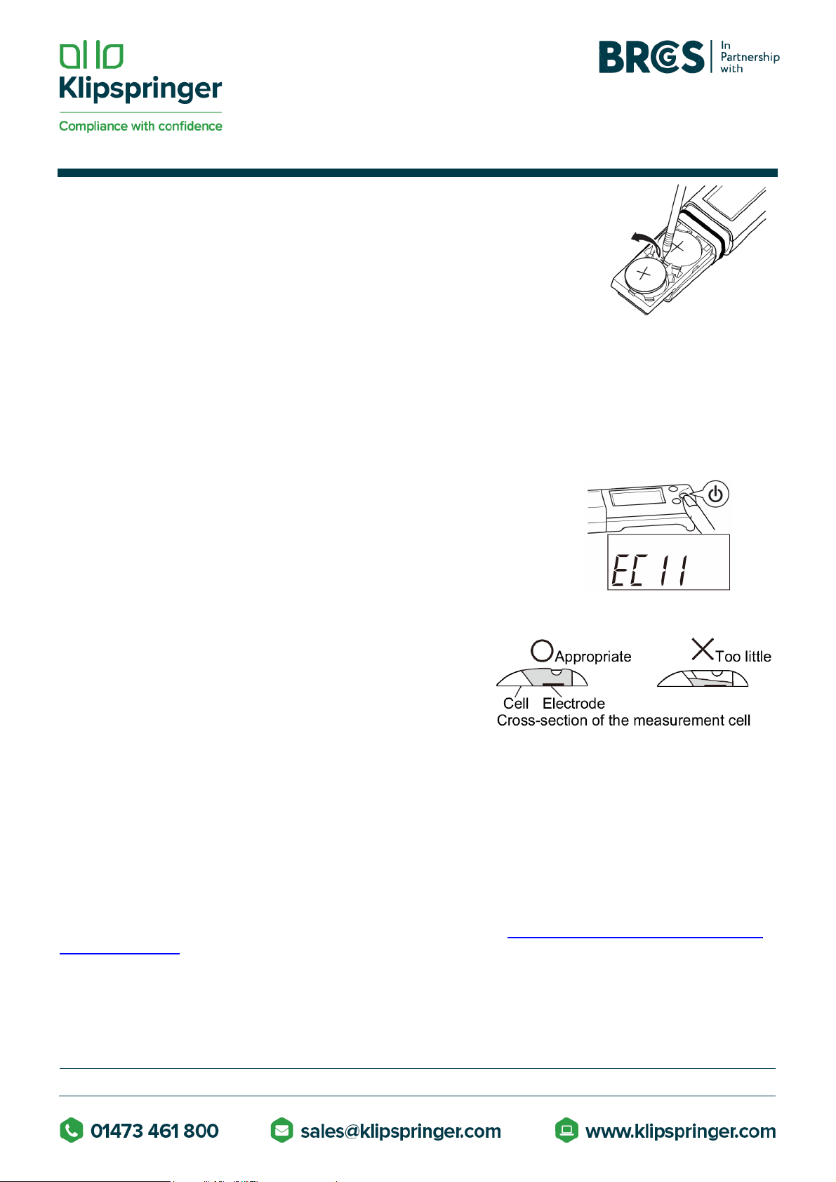
1. Clean the sensor with tap water.
2. Dab gently with soft tissue or cloth to remove moisture on the sensor and meter.
Note: Especially be sure to treat the sensor gently to prevent damaging it.
3. Close the protection cover before storing the meter.
Temperature sensor adjustment:
Temperature sensor adjustment is available on PQ0012 and PQ0013. To perform accurate measurement with
correction for temperature effects, follow the steps below. Normally this is not necessary.
1. Ready a reference thermometer, and allow the meter and reference thermometer to reach to room
temperature.
2. Set the display mode to temperature referring to " Measurement display change" (page 2).
3. Press the CAL switch. The meter displays the setting screen for target temperature.
4. Press the MEAS switch to adjust the displayed temperature on the meter to match the temperature
indicated by the reference thermometer. Pressing the MEAS switch increases the displayed
temperature. After the displayed temperature reaches 400C, it returns to 50C.
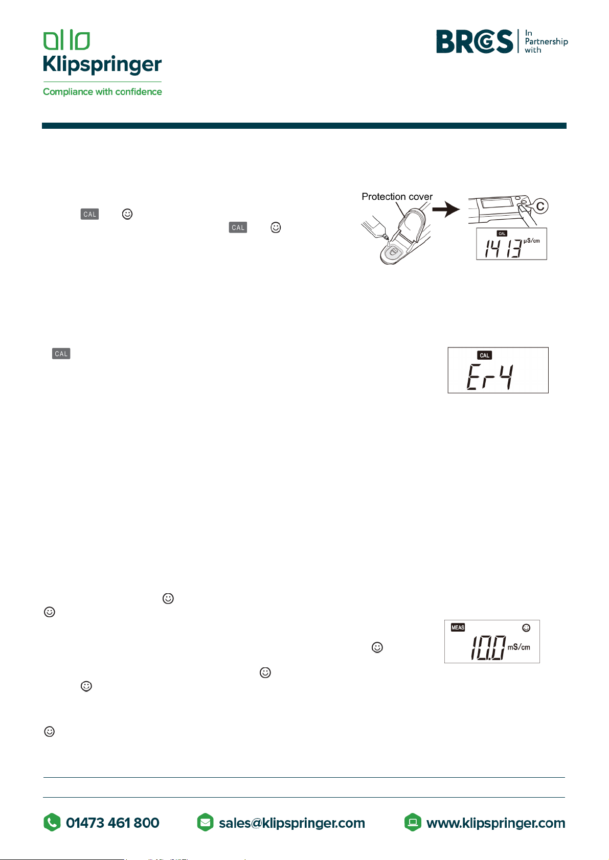
5. Press the CAL switch again to apply the displayed value to the adjustment. The adjustment starts.
The adjusted value blinks with and °C displayed. After the adjustment is complete, the adjusted value stops
blinking with MEAS and °C displayed. If Er4 (error display) appears, the adjustment has failed. Retry the
above steps increasing the time spent on the step 1. If the adjustment repeatedly fails, the sensor may
have deteriorated. Replace the sensor with new one.
Initializing calibration data:
Initialize calibration in the following cases:
•To delete the calibration data

UNCONTROLLED IF PRINTED
PAGE(S) 5 OF
7
•If the number of points for the last calibration is uncertain.
•After the sensor is replaced.
1. Press and hold the CAL and ON/OFF switches for over 3 seconds when
the meter is switched OFF to Initialize calibration. After a moment of all
segment indication, the software version is displayed And then , the display
changes as shown right.
2. Press the CAL switch. All calibration data is reset. When the initialization of
calibration data is complete, End appears. The meter automatically switches
OFF.
Initializing the settings:
All setup choices are erased. The meter is reset to the factory default values.
1. Press and hold the MEAS, CAL and ON/OFF switches for over 3
seconds when the meter is switched OFF to enter the initialization. After
a moment of all segment indication, the software version is displayed. And
then, the display changes as shown right.
2. Press the CAL switch. All calibration data is reset. When the initialization of
settings is complete, End appears. The meter automatically switches OFF.
Appendix
FAQ
How can I check the sensor's condition?
•Perform 2-point calibration. If calibration error occurs, the sensor has deteriorated. Replace the sensor.
Can I measure high or low temperature samples?
•This meter cannot measure a sample with temperatures outside the meter's operating temperature range
(50C to 400C). The difference between the sample temperature and ambient temperature increases the
measurement error. Perform measurement after the sample reaches the ambient temperature.
The measured value does not change after changing the sample.
•If lights steadily in AH mode, the measured value is locked. Press the MEAS switch to unlock the value.
If the value does not change after unlocking, the sensor may be damaged. Replace the sensor.
"Or" or "Ur" blinks in value measurement.
•The measured value may be out of the specified measurement range. Measure a standard solution to
check, and if "Or" or "Ur" still blinks, replace the sensor.
°C blinks during measurement.
•The measured temperature is not within the specified operating temperature (50C to 400C). If the ambient
temperature is within the specified range and oc blinks, replace the sensor.
The meter does not power ON.

UNCONTROLLED IF PRINTED
PAGE(S) 6 OF
7
•Check that the batteries are inserted properly. If the battery voltage is low, replace them both with new
ones at the same time.
Er4 is displayed during the calibration.
•Please note that if you press the CAL switch in mV or temperature display mode, Er4 is displayed. This is
because there is no calibration facility available for these modes.
Er1 is displayed soon power ON.
•The internal IC in the meter may be defective. Perform meter initialization. If Erl is still displayed after the
initialization, the internal IC in the meter is defective. Replace the meter with a new one (the meter cannot
be repaired).
Er2 is displayed right after power ON.
•The internal IC in the meter is defective. Replace the meter with a new one (the meter cannot be repaired).
Er3 is displayed right after power ON.
•The internal IC in the meter is defective. Replace the meter with a new one (the meter cannot be repaired).
Setup Mode
The setup mode allows the user to customize the meter to his specific needs. To enter the setup mode, press and
hold the MEAS and ON/OFF switches for over 3 seconds when the meter is switched OFF. All the LCD segments
appear and then the meter enters the setup mode.
Note: To have the changes apply, you need to go through the entire steps from "Setup mode entry" to "Setup
completion" shown below. To leave a setting as it is, just press CAL switch in the setting. To exit the setup mode
with no change of settings, press the ON/OFF switch earlier than pressing CAL switch in the last step but one, or
the "Backlight setting" step.
Setup mode entry:
Unit setting:
The display units can be changed.
TDS method setting
The TDS method can be selected from the following options only on PQ00133.

UNCONTROLLED IF PRINTED
PAGE(S) 7 OF
7
•FACt: KCI with factor adjustable from 0.4 to 1.0 (default 0.5)
•442: Myron L 442 non-linear standard curve
•En: European environmental standard non-linear curve
•NACL: Non linear salinity curve
This step is bypassed on PQ0011 and PQ0012.
Factor setting (Only PQ0013; TDS method set to FACt)
This step is bypassed on PQ0011 and PQ0012, and when the TDS method is set to 442, En, or NACL on PQ0013.
* The setting range is from FO.4 to Fl .0. In this
setting, pressing the MEAS switch increases the
displayed value. After the displayed value reaches
Fl .0, it returns to FO.4.
Measurement mode change
The measurement mode can be switched.
Note: The AH (auto hold) mode is applied only to
conductivity measurement.
*Measurement display change is available in the
AS mode. Refer to " Measurement display change"
(page 2).
Backlight setting
The backlight can be switched to ON or OFF.
Setup completion
This manual suits for next models
3
Table of contents
Other Klipspringer Measuring Instrument manuals
Popular Measuring Instrument manuals by other brands

C-Tech
C-Tech EDG-1S product manual

BI COMMUNICATIONS
BI COMMUNICATIONS TX8000 Quick start operating instructions

Ohmite
Ohmite FSP Series Integration guide

Beckhoff
Beckhoff EP6070-0060 Documentation

Apera Instruments
Apera Instruments LabSen 753 user manual

Pulsar Measurement
Pulsar Measurement Ultra 3 instruction manual