Manual Pipe Bender
OWNER’S MANUAL
Manual Pipe Bender
OWNER’S MANUAL
Important Safety Information
WARNING:
• Read and understand all instructions. Failure to follow all instructions may result in serious
injury.
• The warnings, cautions, and instructions in this manual cannot cover all possible conditions
or situations that could occur. Exercise common sense and caution when using this tool.
Always be aware of the environment and ensure that the tool is used in a safe and responsi-
ble manner.
• DO NOT allow persons to operate or assemble this product until they have read this manual
and have developed a thorough understanding of how the product works.
• DO NOT modify the product in any way. Unauthorized modification may impair the function
and/or safety and could affect the life of the product. There are specific applications for
which the product was designed.
• Use the right tool for the job. DO NOT attempt to force a small equipment to do the work of
larger industrial equipment. There are certain applications for which this equipment was
designed. It will do the job better and more safely at the capacity for which it was intended.
DO NOT use this equipment for a purpose for which it was not intended.
• Industrial or commercial applications must follow OSHA requirements.
WARNING:
WORK AREA SAFETY
• Inspect the work area before each use. Keep work area clean, dry, free of clutter, and well lit.
Cluttered, wet, or dark work areas can result in injury. Using the tool in confined work areas
may put you dangerously close to other cutting tools and rotating parts.
• Do not use the tool where there is a risk of causing a fire or an explosion; e.g., in the
presence of flammable liquids, gases, or dust. The tool can create sparks, which may ignite
the dust or fumes.
• Do not allow the tool to come into contact with an electrical source. Contact will cause
shock.
• Keep children and bystanders away from the work area while operating the tool. Do not allow
children to handle the tool.
• Be aware of all power lines, electrical circuits, water pipes, and other mechanical hazards in
your work area. Some of these hazards may be below the work surface hidden from your
view and may cause personal harm or property damage if unintentionally contacted.
PERSONAL SAFETY
• Stay alert, watch what you are doing, and use common sense when operating the tool. Do
not use the tool while you are tired or under the influence of drugs, alcohol, or medication. A
moment of inattention while operating the tool may result in serious personal injury.
• Dress properly. Do not wear loose clothing, dangling objects, or jewelry. Keep your hair,
clothing and gloves away from moving parts. Loose clothes, jewelry, or long hair can be
caught.
• Use ANSI-Z87.1 compliant safety goggles or safety glasses with side shields, or when
needed, a face shield to prevent eyeinjury from potential flying metal parts. Use a dust mask
in dusty work conditions. Also use non-skid safety shoes, hardhat, gloves, dust collection
systems, and hearing protection when appropriate. This applies to all persons in the work
area.
• Do not overreach. Keep proper footing and balance at all times.
• Secure the work with clamps or a vise instead of your hand when practical. This safety
precaution allows for proper tool operation using both hands.
CAUTION
BENDER USE AND CARE
• Do not force the tool. Tools do a better and safer job when used in the manner for which they
are designed. Plan your work, and use the correct tool for the job.
• Check for damaged parts before each use. Carefully check that the tool will operate properly
and perform its intended function. Replace damaged or worn parts immediately. Never
operate the tool with a damaged part.
• Store the tool when it is not in use. Store it in a dry, secure place out of the reach of children.
Inspect the tool for good working condition prior to storage and before re-use.
• Use only accessories that are recommended by the manufacturer for use with your tool.
Accessories that may be suitable for one tool may create a risk of injury when used with
another tool. Never use an accessory that has a lower operating speed or operating pressure
than the tool itself.
Specific Operation Warnings
WARNING:
• Alwaysmake sure the bender is firmlysecured to a flat surface that can supportthe weight and
forces during operation. Serious personal injury could result if the bender assembly should
unexpectedlyslip during a bending operation.
•
AVOID MOVING PARTS DURING OPERATION. Keep fingers and handsaway from moving parts.
• CHECK ALL PINS BEFORE USE. Make sure all pins are inserted all ofthe way.
• MAKE SURE STOCK IS OF SUFFICIENT LENGTH. Stock must extendfar enough by the stop
block &forming die so as not to slip and causeinjury.
Assembly
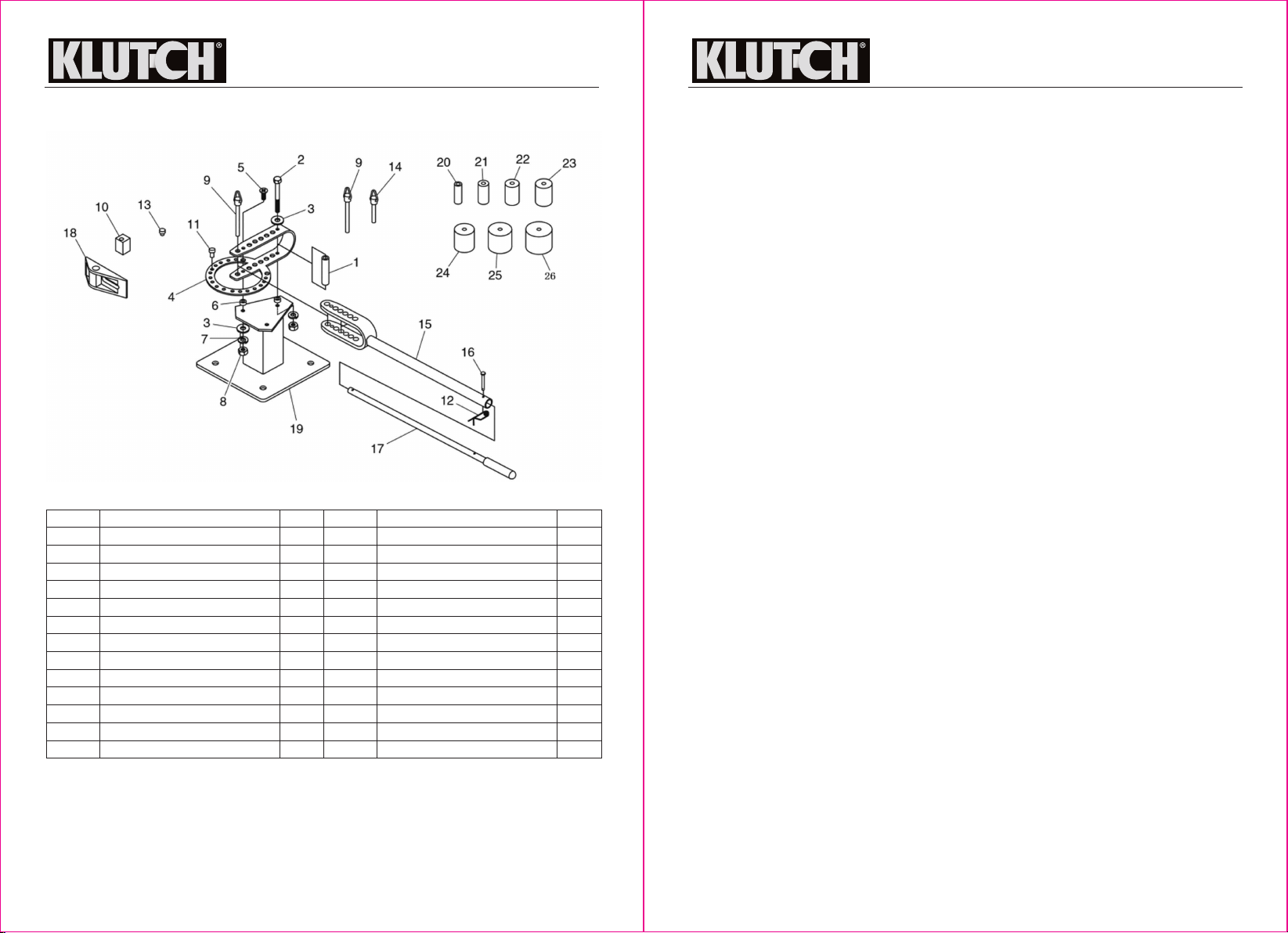
Inventory
The following is a description of the main componentsshipped with your machine. lay the
componentsout to inventory them.
This assembly procedure works for both the bench-top and floor-mounted benders.
1. When first unpacking the bender, check the contents of the shipping carton with the parts
diagram to ensure all parts are present.
2. Bolt the base/stand (19) to a stable surface
3. Place the two short spacers (6) over two of the holes on thetop of the base/stand as shown in
figure 3 below.
2 of 7 3 of 7
Main Components (Figure 2)
A. Base
B. yoke Arm
C. handle
D. Bending Bracket
E. Bending dies
1", 11⁄4", 11⁄2", 13 ⁄4", 2", 21⁄2", 3"
f. Stop pin M10 X 16
g. Block Support pin M9 X 11
h. Stop Block
I. long Spacer M10 x 69
J. Angle Bending Block
Qty.
1
1
1
1
1 Each
1
1
1
1
1