Klutch 48577 User manual

Filter Regulator and Lubricator
Owner’s Manual
Items #48577, #48576, #48575
,
WARNING: Read carefully and understand all ASSEMBLY AND OPERATION
INSTRUCTIONS before operating. Failure to follow the safety rules and other basic safety
precautions may result in serious personal injury.

2
Thank you very much for choosing a Klutch® product!
For future reference, please complete the owner’s record below:
Serial Number/Lot Date Code: ________________________________
Purchase Date: ____________________________________________
Save the receipt, warranty, and this manual. It is important that you read
the entire manual to become familiar with this product before you begin
using it.
This filter regulator and lubricator is designed for certain applications
only. Northern Tool & Equipment is not responsible for issues arising
from modification or improper use of this product such as an application
for which it was not designed. We strongly recommend that this product
not be modified and/or used for any application other than that for which
it was designed.
For technical questions, please call 1-800-222-5381.

3
Table of Contents
Intended Use..........................................................................................................................................4
Technical Specifications......................................................................................................................5
Important Safety Information...............................................................................................................6
Safety Labels.........................................................................................................................................7
Main Parts of Product...........................................................................................................................8
Assembly Instructions........................................................................................................................13
Before Each Use..................................................................................................................................14
Operating Instructions........................................................................................................................14
Troubleshooting..................................................................................................................................15
Maintenance Instructions...................................................................................................................17
Limited Warranty.................................................................................................................................19

4
Intended Use
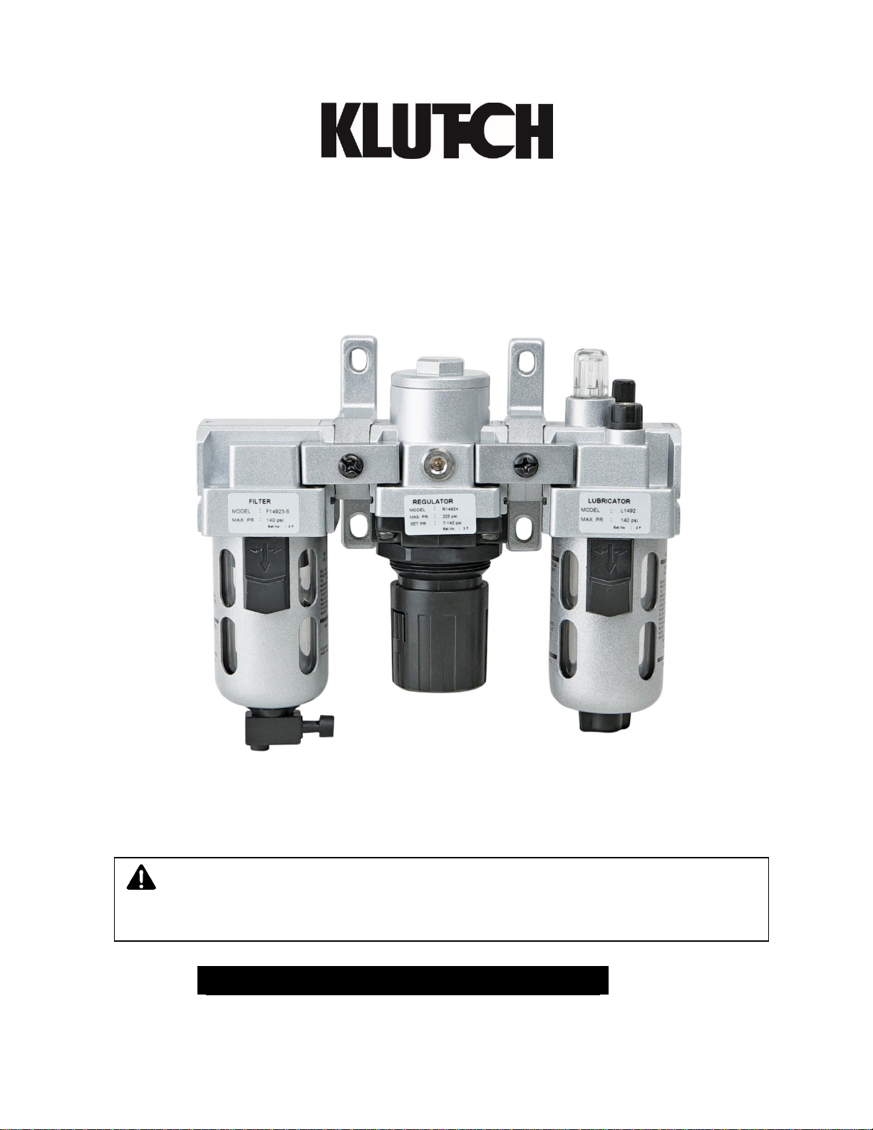
•The Klutch Filter Regulator and Lubricator is one of the most popular air preparation units. The
regulator and lubricator are assembled together to form a single unit.
•The air filter is used to separate dust, dirt, moisture, and other contaminants from compressed air.
•The filter has a die-cast aluminum body, polycarbonate bowl with a steel bowl guard, and a high
performance sintered bronze filtering element.
•Filter is designed with a Separator and Shield for efficient moisture separation. It is combined with
a Regulator which maintains a steady outlet pressure, unaffected by variations/fluctuations in the
inlet pressure.
•The Filter Regulator and Lubricator has a non-raising, press-to-lock adjusting knob for locking at
any set pressure. The Filter Regulator and Lubricator works on a diaphragm-operated, relieving
mechanism with pressure compensated by a balanced poppet.
•Air lubricators are used to feed lubricants to pneumatic equipment. These maintain a constant oil-
to-air density over a wide range of flow.
•The lubricator has fog/micro misting abilities, up to 50-foot pipe runs.
•The head is fitted with an oil drop indicator, an oil drop controller, and an oil filling plug.
•A 1/8” mechanical air pressure gauge is included.
WHY USE A FILTER?
•The air being supplied to the equipment may contain moisture, dust, dirt, or other foreign particles
which can damage the equipment. To prevent damage, install a filter before the equipment.
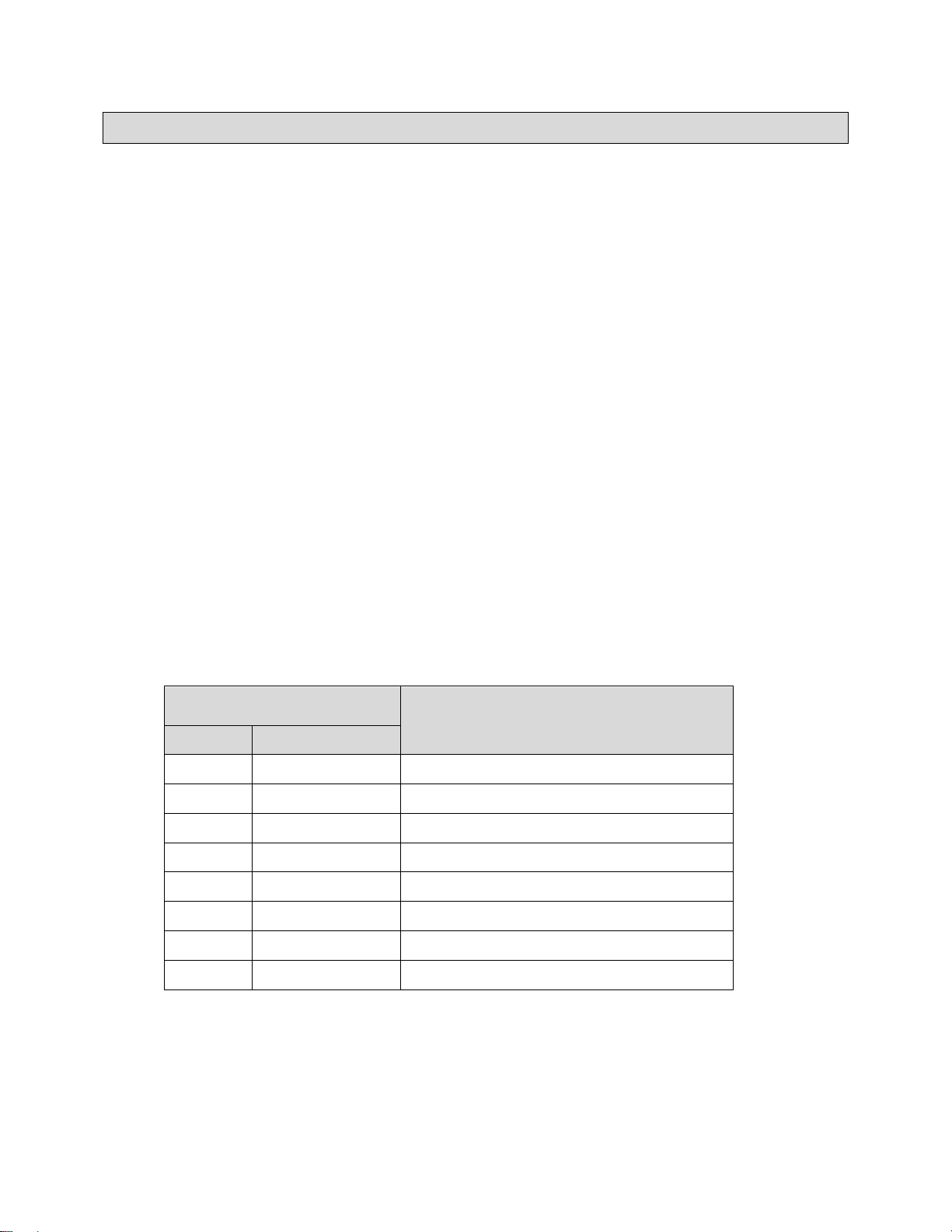
GENERAL SELECTION GUIDE FOR CHOOSING THE CORRECT FILTER BASED ON COMPRESSOR
SIZE
Compressor
Filters
HP
CFM
1HP
Up to 4 CFM
Miniature 1/4”
2 HP
Up to 9 CFM
Miniature 1/4”
3 HP
Up to 13 CFM
Miniature 1/4”
5 HP
Up to 22 CFM
Miniature 1/4”
10 HP
Up to 45 CFM
Intermediate 3/8”
15 HP
Up to 67 CFM
Intermediate 3/8”, Standard 1/2”
20 HP
Up to 90 CFM
Standard 1/2”
25 HP
Up to 112 CFM
Standard 1/2”
STANDARD CONFIGURATION
•40-micron filtering element.
•Press Manual Drain with Night Time Drain feature which automatically drains off the bowl once
the compressed air supply to the filter is switched off.

5
WHY USE A REGULATOR?
Air regulators are used to provide a controlled and consistent air supply as required by different
pneumatic equipment. The knob can be used to adjust the air supply thus resulting in increasing or
decreasing the air pressure.
STANDARD CONFIGURATION
•Pressure adjustment range of 7 - 145 PSI (0.5 - 10 BAR)
OPTIONAL CONFIGURATION
Custom built include the following Pressure Adjustment ranges:
•3 - 28 PSI (0.2 - 2 BAR)
•3 - 58 PSI (0.2 - 4 BAR)
•8 - 100 PSI (0.5 - 7 BAR)
WHY USE A LUBRICATOR?
Air lubricators are used with air supply lines where the compressed air is required to be lubricated before
being supplied to the tool /equipment.
WETTED COMPONENTS
Aluminum, Bronze, Steel, Acetal, Polycarbonate, Stainless Steel & Nitrile, Brass
Technical Specifications
Part
No.
Port
Size
Flow Rate
(Max)**
Pressure
Gauge
Bowl
Size (Filter)
Bowl Size
(Lubricator)
Height
Width
CFM
LMP
Port Size
oz.
ml
oz.
ml
Inch
mm
In
mm
48577
1/4"
18
500
1/8"
0.3
9
0.68
20
6.69
170
7.87
200
48575
3/8"
71
2000
1/8"
1.08
32
1.93
57
8.66
220
9.84
250
48576
1/2"
106
3000
1/8"
1.5
44
5.17
152
11.0
280
12
305
Part Number
Port Size
Mechanical Pressure Gauge
48577
1/4"
✓
48575
3/8”
✓
48576
1/2”
✓

6
Important Safety Information
⚠WARNING
•Read and understand all instructions. Failure to follow all instructions may result in serious injury
or property damage.
•The warnings, cautions, and instructions in this manual cannot cover all possible conditions or
situations that could occur. Exercise common sense and caution when using this tool. Always be
aware of the environment and ensure that the tool is used in a safe and responsible manner.
•Do not allow persons to operate or assemble the product until they have read this manual and
have developed a thorough understanding of how it works.
•Do not modify this product in any way. Unauthorized modification may impair the function and/or
safety and could affect the life of the product. There are specific applications for which the
product was designed.
•Use the right tool for the job. DO NOT attempt to force small equipment to do the work of larger
industrial equipment. There are certain applications for which this equipment was designed. It will
be a safer experience and do the job better at the capacity for which it was intended. DO NOT
use this equipment for a purpose for which it was not intended.
•Industrial or commercial applications must follow OSHA requirements.
⚠WARNING
WORK AREA SAFETY
•Inspect the work area before each use. Keep work area clean, dry, free of clutter, and well-lit.
Cluttered, wet, or dark work areas can result in injury. Using the product in confined work areas
may put you dangerously close to other cutting tools and rotating parts.
•Do not use the product where there is a risk of causing a fire or an explosion; e.g., in the
presence of flammable liquids, gases, or dust. The product can create sparks, which may ignite
the flammable liquids, gases, or dust.
•Do not allow the product to come into contact with an electrical source. The tool is not insulated
and contact will cause electrical shock.
•Keep children and bystanders away from the work area while operating the tool. Do not allow
children to handle the product.
•Be aware of all power lines, electrical circuits, water pipes, and other mechanical hazards in your
work area. Some of these hazards may be hidden from your view and may cause personal injury
and/or property damage if contacted.

7
⚠WARNING
PERSONAL SAFETY
•Stay alert, watch what you are doing, and use common sense when operating the tool. Do not use
the tool while you are tired or under the influence of drugs, alcohol, or medication. A moment of
inattention while operating the tool may result in serious personal injury.
•Dress properly. Do not wear loose clothing, dangling objects, or jewelry. Keep your hair, clothing
and gloves away from moving parts. Loose clothes, jewelry, or long hair can be caught in moving
parts. Air vents on the tool often cover moving parts and should be avoided.
•Wear the proper personal protective equipment when necessary. Use ANSI Z87.1 compliant safety
goggles (not safety glasses) with side shields, or when needed, a face shield. Use a dust mask in
dusty work conditions. Also use non-skid safety shoes, hardhat, gloves, dust collection systems,
and hearing protection when appropriate. This applies to all persons in the work area.
•Do not overreach. Keep proper footing and balance at all times.
⚠CAUTION
PRODUCT USE AND CARE
•Do not force the product. Products are safer and do a better job when used in the manner for
which they are designed. Plan your work, and use the correct product for the job.
•Check for damaged parts before each use. Carefully check that the product will operate properly
and perform its intended function. Replace damaged or worn parts immediately. Never operate
the product with a damaged part.
•Store the product when it is not in use. Store it in a dry, secure place out of the reach of children.
Inspect the tool for good working condition prior to storage and before re-use.
•Use only accessories that are recommended by the manufacturer for use with your product.
Accessories that may be suitable for one product may create a risk of injury when used with
another tool. Never use an accessory that has a lower operating speed or operating pressure
than the tool itself.
•Keep guards in place and in working order. Never operate the product without the guards in
place.
Safety Labels
Conforms To:
IS0 6953-1
IS0 5782-1
IS0 6301-1

8
Main Parts of Product
AIR FILTER
Reference
Description
Qty.
Internal Plastic Spares
1
Housing
1
2
Stud
1
3
Separator
1
4
Shield
1
5
Filter Element –40 Microns
1
Reference
Description
Qty.
6
Filter Holder
1
7
Bowl with O-ring
1
7.1.1
Polycarbonate Bowl
1
7.1.2
O-ring
1
7.2
Drain Valve Assembly (Semi-Automatic)
1
7.2.1
Gland Assembly
1
7.2.1a
Gland
1
7.2.1b
Valve Seat
1
7.2.1c
Spring
1
7.2.1d
Spring Guide Nut
1

9
Reference
Description
Qty.
7.2.2
Sealing Washer
1
7.2.3
O ring
1
7.2.4
Actuator
1
7.2.5
Stem Housing Assembly
1
7.3
Metal Bowl Guard
1
7.3.1
Locking Piece
1

10
AIR REGULATOR

11
Reference
Description
Qty.
1
Knob
1
2
Locknut
1
3
Indicator Ring
1
4
Philip Head Screw
4
5
Bonnet
1
6
Bearing Washer
1
7
Adjusting Screw Assembly
1
8
Main Spring
1
9
Diaphragm Assembly
1
10
Venturi Tube
1
11
Housing
1
12
Port Plug Assembly
2
12.1
Port Plug
2
12.2
O-ring
2
13
Valve Cone Assembly
1
14
Bottom Spring
1
15
O-ring
1
16
Bottom Plug
1
16.1
O-ring
1
17
O-ring
1
18
Circlip
1

12
AIR LUBRICATOR

13
Reference
Description
Qty.
1
Sight Dome Assembly
1
1.1
Oil Drop Indicator
1
1.2
Oil Drop Controller
1
1.3
O-ring
1
1.4
O-ring
1
2
Oil Filling Plug Assembly
1
2.1
Oil Filling Plug
1
2.2
O-ring
1
3
Needle Assembly
1
3.1
Needle Housing Assembly
1
3.1.1
Knob
1
3.1.2
O-ring
1
3.2
O-ring
1
3.3
O-ring
1
4
Housing
1
5
Connector Assembly
1
5.1
Connector
1
5.2
Ball
1
5.3
O-ring
1
6
Jet Deflector
1
7
Valve Seat
1
8
Deflector Retainer Assembly
1
9
Philip Head Screw
2
10
Suction Tube
1
11
Oil Filter
1
12
Bowl & Bowl Guard Assembly
1
12.1
Bowl Assembly
1
12.1.1
Bowl
1
12.1.2
O-ring
1
12.2
Gland Plug Assembly
1
12.2.1
Gland Plug
1
12.2.2
Sealing Washer
1
12.2.3
O-ring
1
12.2.4
Gland Nut
1
12.3
Bowl Guard
1
12.3.1
Locking Piece
1
Assembly Instructions
1. Install product in a clean, acid-free atmosphere.
2. Flush the piping for dirt, dust, and other foreign particles.
3. Connect the supply pressure to the IN port and take the outlet from the OUT port. (If the unit is
installed in reverse direction, the air will continuously flow through the bonnet and the setting of the
pressure will not be possible.)
4. Use proper thread sealant for taper threads to have a leak-proof connection.
5. Set the pressure in the regulator within the specified limit, otherwise the spring may break.
6. Open the inlet valve/switch on the air supply.
7. When using parallel thread nipples, check the length of the thread from the given table.

14
8. To mount the combination onto a wall, the clamp has a hole into which the regulator fits in and is
secured by the nut provided in the regulator itself.
Before Each Use
WHERE TO INSTALL A FILTER?
Install as far away from the compressor as possible. This allows air to cool and moisture to condense.
It is easier to remove condensed moisture than vapers. Place unit:
•As close to tool/equipment as possible,
•Before Regulator and Lubricator, and
•With arrows pointing in direction of air flow (towards tool/equipment).
WHERE TO INSTALL A REGULATOR?
•As close to tool or equipment as possible to avoid any further pressure loss,
•Between the filter and lubricator, and
•With arrows pointing in the direction of air flow (towards tool/equipment).
WHERE TO INSTALL A LUBRICATOR?
•As close as to tool or equipment to avoid any further pressure loss,
•Lubricator should be the last component in the FRL series, and
•With arrows pointing in the direction of air flow (towards tool/equipment).
Thread Size
Tightening Torque,
Lb. - In (Nm)
Length (L) of Thread
G1/4
106 - 125 (12 - 14)
8 mm Max.
G3/8
195 - 215 (22 - 24)
9 mm Max.
G1/2
250 - 270 (28 - 30)
12 mm Max.
Operating Instructions
Refer to the parts diagrams and parts lists.
1. To set the regulator, pull the regulating knob till “Red Band” (indicator ring) is visible.
2. To increase the pressure, turn the regulating knob in a clockwise direction.
3. To reduce the pressure, turn the regulating knob in counter-clockwise direction.
4. Always set the pressure in the ascending manner.
5. Set the pressure within the specified limit.
6. To drain the condensate water collected in the bowl (7.1.1 “Air Filter”), press and hold the knob of
the drain valve (7.2 Air Filter).

15
7. It is advisable to drain the bowl every day. The frequency of draining can be decided based on
the condensate collection.
8. Take care that the condensate level does not exceed the Max Level mark on the bowl guard.
9. To adjust the oil flow, turn the lubricator knob to adjust the oil drops to your need: clockwise to
decrease and counter-clockwise to increase the oil flow.
Note: The lubricator is designed for best performance with a 32-grade oil.
Troubleshooting
Air Filter
Refer to the Air Filter’s Parts Diagram and Parts List. Use the table below to troubleshoot problems before
contacting a technician or your local dealer. If the problem continues after troubleshooting, call your local
dealer for assistance.
Problem
Cause
Solution
1. Restricted air flow.
Filter element (5)
clogged.
Clean the filter element and
replace.
2. Water level not visible.
Dirt on the inner surface
of the polycarbonate
bowl (7.1.1).
Clean the polycarbonate bowl.
3. Air leaks from housing (1) and
metal bowl guard (7.3) interface.
O ring (7.1.2) damaged.
Replace the O-ring.
4. Air leaks from the bottom of the
metal bowl guard.
O ring (7.2.3) damaged.
Replace the O-ring.
5. Air leaks continuously through the
drain valve assembly (7.2).
Drain valve assembly
damaged.
Replace the drain valve
assembly.
6. The knob of drain valve does not
return.
Valve components
stuck.
Pull the knob and operate. If the
valve gets stuck again - replace
the semi auto drain valve
assembly.
Air Regulator
Refer to Figures 2 & 3
Problem
Cause
Solution
1. Continuous flow/
leak through the
knob.
1. Diaphragm assembly (9) is damaged.
Replace diaphragm assembly (9).
2. The seating on the valve cone is
damaged.
Replace the valve cone assembly
(13).
3. Dirt found in between the seating and
the valve cone (13).
3. Clean and reassemble.

16
Problem
Cause
Solution
2. Setting pressure
slows.
1. The seat on the valve cone is
damaged.
1. Replace the valve cone assembly
(13).
2. Dirt found in between the seating and
the valve cone.
2. Clean the seating area and
reassemble.
3. After frequent
use of
adjustment knob,
the pressure
setting is difficult
to change.
Adjusting screw (7) is worn.
Replace after applying general
purpose grease on threads and at
bearing washer (6).
4. It’s difficult to set
the outlet
pressure.
Pressure is either too high or too low.
Dismantle the valve cone assembly.
Clean using kerosene and air jet,
reassemble after applying general
purpose grease on O-ring (12.2) and
on the valve cone cylindrical portion.
⚠CAUTION
When the unit is mounted in a salty atmosphere, there are good chances of formation of aluminum
oxide inside the housing. In due course the valve cone may get stuck. In this case, dismantle the
components and clean them using kerosene and air jet. During reassembly, apply general purpose
grease on all inside surfaces of the housing as protection against corrosion. Also apply grease on
the O-rings and cylindrical portion of the valve cone.
Air Lubricator
Refer to the Air Lubricator’s Parts Diagram and Parts List. Use the following table to troubleshoot
problems before contacting service technicians or your local dealer. If the problem continues after
troubleshooting, call your local dealer for assistance.
Problem
Cause
Solution
1. Oil does not flow.
1. Wrong port
connection.
1. Change the port connection.
2. Air flow rate
insufficient.
2. Refer specification and
select the model.
3. Oil below “minimum
oil level”.
3. Pour oil.
4. Oil adjusting screw
in closed condition.
4. Adjust oil drops to your
requirement.
5. Oil filter (11)
clogged.
5. Clean and reassemble.
6. Oil path is clogged.
6. Dismantle the unit. Clean
the oil path with air jet and
reassemble.

17
Problem
Cause
Solution
2. Oil leak through needle assembly
(3).
O-ring (3.1.2) damaged.
Replace O-ring.
3. Oil leak through housing and
needle assembly.
O-ring (3.2) damaged.
Replace the O-ring.
4. Flow of oil not adjustable.
O-ring (5.3) damaged.
Replace the O-ring.
5. Air bubbles along with oil drop.
O-ring (3.3) damaged.
Replace the O-ring.
6. Oil drops not visible through oil
drop indicator (1.1).
O-ring (1.4) damaged.
Replace the O-ring.
7. Air leak through sight dome (1).
O-ring (1.3) damaged.
Replace the O-ring.
8. Air leak through housing (4) and
bowl guard (12) interface.
O-ring (12.1.2)
damaged.
Replace the O-ring.
9. Air leak at gland plug (12.2.1) and
bowl guard (12) interface.
O-ring (12.2.3)
damaged.
Replace the O-ring.
10. Air leaks through oil filling plug
(2.1).
O-ring (2.2) damaged.
Replace the O-ring.
Maintenance Instructions
Air Filter
Refer to the Air Filter’s Parts Diagram and Parts List.
48577
48575
48576
Dismantle the Filter
1. Before dismantling the unit, exhaust the air in the line completely.
2. To clean the filter:
a. Unscrew the threaded bowl guard (7.3) in
a counter-clockwise direction. Dismantle
the components and clean the filter
element and blow with compressed air.
b. Lift the metal bowl guard (7.3) upward and pull
down the locking piece (7.3.1). Turn the bowl guard
45° and pull down.
3. Check for damages in the O-rings and other parts. Replace if needed or clean and reassemble.
4. Apply general purpose grease on the O-rings and on the surface of the housing where the O- ring
enters the housing (1). Reassemble all components.
5. Screw the threaded bowl guard (7.3) on
to the housing (1).
5. Position the top flange lug portion of the bowl guard
(7.3) to the corresponding slots in the housing (1).
Push the bowl guard fully into the housing. Turn the
bowl guard 45° until the locking piece (7.3.1) enters
the housing slot fully.

18
Air Regulator
Refer to the Air Regulator’s Parts Diagram and Parts List.
48577
48575
48576
1. Before dismantling the unit, exhaust the air in the line completely.
2. Dismantle the components and clean them in kerosene and blow with compressed air.
3. Check for damages in the O-rings (15), (16.1), (17) and at sealing areas in the valve cone rubber,
spherical relieving seating, seating area of the housing, etc. Replace if needed or clean and
reassemble.
4. For assembly of the unit, apply general purpose grease on the O-rings (15), (16.1), (17), on the
cylindrical surface of the valve cone (13), on threads of the adjusting screw (7), and on bearing
washer (6). Reassemble all the components.
Air Lubricator
Refer to the Air Lubricator’s Parts Diagram and Parts List.
48577
48575
48576
1. Before dismantling the unit, exhaust the air in the line completely.
2. To clean the lubricator:
a. Unscrew the threaded bowl and bowl guard
assembly (12) counter-clockwise. Dismantle
the components and clean the bowl (12.1.1)
and blow with compressed air.
b. Lift the bowl and bowl guard assembly (12)
upwards. Pull down the locking piece (12.3.1).
Turn the bowl guard 45° and pull down.
3.Check for damages in the O-rings and other parts. Replace if needed or clean and reassemble.
4.Apply general purpose grease on the O-rings and on the surface of the housing where the O- ring
enters the housing (4). Reassemble all the components.
5. Screw the threaded bowl guard (12) onto the
housing (4).
5. Position the top flange lug portion of the bowl
guard (12) to the corresponding slots in the
housing (4). Push the bowl guard fully into the
housing. Turn the bowl guard 45° until the locking
piece (12.3.1) enters the housing slot fully.

19
Limited Warranty
Northern Tool and Equipment Company, Inc. ("We'' or '"Us'') warrants to the original purchaser only
("You'' or “Your”) that the Klutch product purchased will be free from material defects in both materials
and workmanship, normal wear and tear excepted, for a period of one year from date of purchase. The
foregoing warranty is valid only if the installation and use of the product is strictly in accordance with
product instructions. There are no other warranties, express or implied, including the warranty of
merchantability or fitness for a particular purpose. If the product does not comply with this limited
warranty, Your sole and exclusive remedy is that We will, at our sole option and within a commercially
reasonable time, either replace the product or product component without charge to You or refund the
purchase price (less shipping). This limited warranty is not transferable.
Limitations on the Warranty
This limited warranty does not cover: (a) normal wear and tear; (b) damage through abuse, neglect,
misuse, or as a result of any accident or in any other manner; (c) damage from misapplication,
overloading, or improper installation; (d) improper maintenance and repair; and (e) product alteration in
any manner by anyone other than Us, with the sole exception of alterations made pursuant to product
instructions and in a workmanlike manner.
Obligations of Purchaser
You must retain Your product purchase receipt to verify date of purchase and that You are the original
purchaser. To make a warranty claim, contact Us at 1-800-222-5381, identify the product by make and
model number, and follow the claim instructions that will be provided. The product and the purchase
receipt must be provided to Us in order to process Your warranty claim. Any returned product that is
replaced or refunded by Us becomes our property. You will be responsible for return shipping costs or
costs related to Your return visit to a retail store.
Remedy Limits
Product replacement or a refund of the purchase price is Your sole remedy under this limited warranty or
any other warranty related to the product. We shall not be liable for: service or labor charges or damage
to Your property incurred in removing or replacing the product; any damages, including, without limitation,
damages to tangible personal property or personal injury, related to Your improper use, installation, or
maintenance of the product or product component; or any indirect, incidental or consequential damages
of any kind for any reason.
Assumption of Risk
You acknowledge and agree that any use of the product for any purpose other than the specified use(s)
stated in the product instructions is at Your own risk.
Governing Law
This limited warranty gives You specific legal rights, and You also may have other rights which vary from
state to state. Some states do not allow limitations or exclusions on implied warranties or incidental or
consequential damages, so the above limitations may not apply to You. This limited warranty is governed
by the laws of the State of Minnesota, without regard to rules pertaining to conflicts of law. The state
courts located in Dakota County, Minnesota shall have exclusive jurisdiction for any disputes relating to
this warranty.

20
Distributed by:
Northern Tool & Equipment Company, Inc.
Burnsville, Minnesota 55306
www.northerntool.com
Made in India
This manual suits for next models
2
Table of contents
Popular Water Filtration System manuals by other brands

Survivor Filter
Survivor Filter L600D Product guide

Argo-Hytos
Argo-Hytos FNA1 008 manual

AFRISO
AFRISO FloCo-Top-2 Series operating instructions

Formula Air
Formula Air E-PURE ASPRA P10000 manual

Premier Tech Aqua
Premier Tech Aqua Ecoflo STB-650B owner's manual

Project Source
Project Source F-7 quick start guide