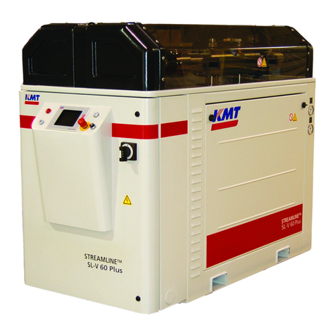
KMT STREAMLINE S50 User manual

MANUAL 20479050(R04)
STREAMLINE S50
WATERJET INTENSIFIER
OPERATION AND MAINTENANCE MANUAL

20479315
2-2012/Rev 03
NOTICE
This document contains subject matter in which KMT Waterjet Systems has
proprietary rights. Recipients of this document shall not duplicate, use or disclose
information contained herein, in whole or in part, for other than the purpose for
which this manual was provided.
KMT Waterjet believes the information described in this manual to be accurate and
reliable. Much care has been taken in its preparation; however, the Company cannot
accept any responsibility, financial or otherwise, for any consequences arising out of
the use of this material. The information contained herein is subject to change, and
revisions may be issued advising of such changes and/or additions.
KMT WATERJET SYSTEMS 2012
KMT Waterjet Systems
635 West 12th Street
PO 231
Baxter Springs, KS 66713-0231
Phone:
Fax: (800) 826-9274
(620) 856-5050

20479315
2-2012/Rev 03 i
TABLE OF CONTENTS
Title Page
Notice
Table of Contents
Appendix
Section Page
1Introduction.......................................................................................................1-1
1.1 Overview................................................................................................1-1
1.2 Performance Features.............................................................................1-1
1.3 Operational Overview............................................................................1-2
Low Pressure Water System..................................................................1-2
Recirculation System.............................................................................1-2
Hydraulic System...................................................................................1-2
High Pressure Water System .................................................................1-2
1.4 Safety .....................................................................................................1-3
Lockout/Tagout Procedure.....................................................................1-4
Warning Labels......................................................................................1-4
Emergency Medical Treatment..............................................................1-6
1.5 Worldwide Product Support ..................................................................1-7
1.6 Spare Parts .............................................................................................1-7
1.7 Manual Organization .............................................................................1-7
1.8 Equipment and Service Manual Questionnaire......................................1-8
Terms and Conditions of Sale
Terms and Conditions, Part Sales
Terms LD-146, Domestic Service Supervisor
Terms LD-147, International Service Supervisor
2Installation.........................................................................................................2-1
2.1 Overview................................................................................................2-1
2.2 Installation Summary.............................................................................2-1
2.3 Site Requirements..................................................................................2-2
Transporting...........................................................................................2-2
2.4 Power Requirements..............................................................................2-3
2.5 Service Connections...............................................................................2-4
Cooling Water (Oil-to-Water Models)...................................................2-5
Cutting Water.........................................................................................2-5
Drain ......................................................................................................2-6
Plant Air.................................................................................................2-6
Contaminated Waste Drain....................................................................2-6
2.6 Flow Requirements................................................................................2-7

20479315
2-2012/Rev 03 ii
2.7 High Pressure Piping..............................................................................2-7
Measurements and Dimensions .............................................................2-8
Hand Coning..........................................................................................2-9
Power Coning.........................................................................................2-10
Hand Threading .....................................................................................2-11
Power Threading....................................................................................2-11
2.8 High Pressure Connections....................................................................2-12
Standard Connections ............................................................................2-12
Anti-Vibration Connections...................................................................2-13
2.9 Commissioning......................................................................................2-14
2.10 Decommissioning ..................................................................................2-16
3Maintenance ......................................................................................................3-1
3.1 Overview................................................................................................3-1
3.2 Maintenance...........................................................................................3-1
Daily Inspection.....................................................................................3-1
Periodic Maintenance.............................................................................3-1
High Pressure System Maintenance.......................................................3-2
3.3 Maintenance Precautions.......................................................................3-3
3.4 Tool Kit..................................................................................................3-3
4Low Pressure Water System............................................................................4-1
4.1 Overview................................................................................................4-1
4.2 Cutting Water Supply Quality ...............................................................4-1
4.3 Operation................................................................................................4-1
4.4 Service and Maintenance Procedures ....................................................4-2
Filter Assembly and Strainer Maintenance............................................4-3
Booster Pump Adjustment.....................................................................4-4
5Recirculation System ........................................................................................5-1
5.1 Overview................................................................................................5-1
5.2 Operation (Oil-to-Water Models)..........................................................5-1
5.3 Operation (Oil-to-Air Models)...............................................................5-2
5.4 Service and Maintenance Procedures ....................................................5-3
Hydraulic Oil Maintenance....................................................................5-3
Electric Motor Bump .............................................................................5-6
Oil Filter Maintenance...........................................................................5-6
Operating Temperature Adjustment (Oil-to-Water Models).................5-7
6Hydraulic System..............................................................................................6-1
6.1 Overview................................................................................................6-1
6.2 Operation................................................................................................6-1
6.3 Service and Maintenance Procedures ....................................................6-2
Hydraulic Operating Pressure................................................................6-3
Motor Maintenance................................................................................6-4
Hydraulic Compensator Maintenance....................................................6-4

20479315
2-2012/Rev 03 iii
7Electrical System...............................................................................................7-1
7.1 Overview................................................................................................7-1
7.2 Sensors and Solenoids............................................................................7-1
7.3 Service and Maintenance Procedures ....................................................7-5
Proximity Switch Maintenance..............................................................7-5
8High Pressure Water System...........................................................................8-1
8.1 Overview................................................................................................8-1
8.2 Operation................................................................................................8-1
8.3 System Components...............................................................................8-3
8.4 Service and Maintenance Overview ......................................................8-4
Torque Specifications ............................................................................8-5
Specialized Maintenance Tools .............................................................8-7
8.5 High and Low Pressure Water Piping....................................................8-8
8.6 High Pressure Cylinder Assembly.........................................................8-8
High Pressure Cylinder Assembly Removal..........................................8-9
High Pressure Cylinder Assembly Installation......................................8-10
High Pressure Cylinder Maintenance ....................................................8-11
8.7 Hard Seal End Caps...............................................................................8-11
Hard Seal End Cap Removal .................................................................8-11
Hard Seal End Cap Installation..............................................................8-12
8.8 Sealing Head..........................................................................................8-13
High Pressure Discharge Check Valve..................................................8-13
Low Pressure Inlet Check Valve............................................................8-15
Sealing Head Maintenance ....................................................................8-16
8.9 High Pressure Seal Assembly................................................................8-16
8.10 Hydraulic Cartridge Seal and Plunger Removal....................................8-18
Plunger Maintenance .............................................................................8-21
Plunger Installation................................................................................8-21
Hydraulic Cartridge Seal Installation.....................................................8-21
8.11 Hydraulic Piston.....................................................................................8-23
Hydraulic Piston Removal.....................................................................8-23
Bearing Rings and Seal Assembly.........................................................8-25
Plunger Button Sockets, Seals and Retainer Pins..................................8-25
Internal Check Valves............................................................................8-26
Hydraulic Piston Installation..................................................................8-26
8.12 Hydraulic Cylinder Maintenance...........................................................8-28
8.13 High Pressure Attenuator.......................................................................8-28
8.14 High Pressure Dump Valve ...................................................................8-29
Pneumatic Control Valve.......................................................................8-29
Pneumatic Actuator................................................................................8-33
8.15 Weep Holes............................................................................................8-34

20479315
2-2012/Rev 03 iv
9Troubleshooting ................................................................................................9-1
9.1 Overview................................................................................................9-1
9.2 Troubleshooting Guide ..........................................................................9-2
10 Specifications.....................................................................................................10-1
10.1 Overview................................................................................................10-1
10.2 Installation Specifications......................................................................10-1
Environment...........................................................................................10-1
Equipment Dimensions and Weights.....................................................10-1
Service Connections...............................................................................10-2
Plant Air.................................................................................................10-2
10.3 Water Specifications..............................................................................10-2
Cutting Water Supply ............................................................................10-2
Recirculation System.............................................................................10-3
Water Quality Standards........................................................................10-4
10.4 Electrical Specifications.........................................................................10-6
Electrical System ...................................................................................10-6
Ampacity and Power Voltage Requirements.........................................10-6
10.5 Hydraulic and High Pressure System Specifications.............................10-6
Hydraulic System...................................................................................10-6
High Pressure Water System .................................................................10-6
Orifice Capacity.....................................................................................10-8
Torque Specifications ............................................................................10-8
11 Parts List............................................................................................................11-1
11.1 Overview................................................................................................11-1
11.2 Index ......................................................................................................11-2
APPENDIX
Exhibit
System Schematic
Electrical Schematic(s)
Material Safety Data Sheets

20479258
2-2012/Rev 02 1-1
SECTION 1
INTRODUCTION
1.1 Overview
The Streamline S50, specifically designed for integration into a waterjet cutting system, combines
all the unique capabilities and advantages of waterjet cutting with the reliability, ease of operation
and service support that have made KMT Waterjet Systems a leader in waterjet technology.
Available with an oil-to-water or an oil-to-air heat exchanger, the S50 does not include a control
panel or enclosure and will not run as a stand-alone unit. An electrical interface allows the
system builder to supply all power, control and logic interface to the intensifier from the motion
control panel. The entire cutting system can be operated and controlled from one location.
Table 1-1
Streamline S50
Motor
Horsepower
Rating Operating
Frequency Maximum Deadhead
Pressure Maximum Flow Rate
(at full pressure)
Maximum Single
Orifice Diameter
(at fill pressure)
HP Kw
50 37 50Hz 55,000 psi (3,792 bar)* 0.95 gpm (3.6 L/min) 0.014 inch (0.36 mm)
60Hz 60,000 psi (4,137 bar) 0.86 gpm (3.3 L/min) 0.013 inch (0.33 mm)
* To operate at 60,000 psi (4,137 bar) maximum deadhead and 50 Hz operating frequency, a second high
pressure attenuator must be added (Kit P/N 20479544).
1.2 Performance Features
The S50 is designed with the same convenience and ease of access for maintenance and service
you have come to expect from KMT Waterjet. The hydraulic cylinder head simply bolts to the
hydraulic cylinder; each high pressure assembly can be removed and serviced independently, and
the hydraulic seal cartridge can be quickly replaced as a single unit.
The robust performance and standard features are the result of aggressive development and
decades of experience.
Deadhead at 60,000 psi (4,137 bar).
The innovative hard seal end cap provides a metal-to-metal seal against the sealing head,
totally, eliminating the potential for leaks.
While dramatically increasing seal life, the unique design of the patented HyperLifeTM
seal conforms to the cylinder bore as it expands under pressure, creating an absolute seal.
Each long, slow stroke of the plunger moves more water, while reducing seal and
component wear.

Section 1
Introduction
20479258
2-2012/Rev 02 1-2
1.3 Operational Overview
The following provides a brief overview of the function and primary components associated with
the individual systems. A detailed discussion of each system is provided in Sections 4 through 8.
Low Pressure Water System
The low pressure water system supplies the cutting water flow to the intensifier. Major system
components include the water filter assembly and the booster pump.
Figure 1-1: System Components
Recirculation System
The recirculation system is a cooling and filtration system that provides properly conditioned oil
to the main hydraulic system. Major system components include the recirculation pump, heat
exchanger, oil filter assembly and the hydraulic oil reservoir.
Hydraulic System
The hydraulic system supplies the intensifier with the hydraulic oil required to produce high
pressure water. Major system components include the electric motor, hydraulic pump and a 4-
way directional control valve mounted on the hydraulic manifold.
High Pressure Water System
The high pressure water system is the heart of the waterjet system. Water is pressurized and
continuously delivered to the cutting head. As water passes through a tiny hole in the orifice,
water pressure is converted to water velocity capable of cutting most any material.

Section 1
Introduction
20479258
2-2012/Rev 02 1-3
The major components include the high pressure cylinder assemblies, hydraulic cylinder
assembly, hydraulic piston, attenuator and the safety dump valve.
Figure 1-2: High Pressure Water System Components
1.4 Safety
The high pressure waterjet cutting system is a high energy cutting tool capable of cutting many
dense or strong materials. Do not touch or be exposed to high pressure water. High pressure
water will penetrate all parts of the human body. The liquid stream and the material ejected by
the extreme pressure can result in severe injury.
All personnel operating, servicing or working near the waterjet cutting equipment shall adhere to
the following safety precautions, as well as the applicable plant safety precautions.
Only KMT factory trained, qualified personnel shall service and maintain the
equipment.
The operator shall practice and promote safety at all times to avoid potential
injury and unnecessary downtime.
The work area around the equipment shall be clean and free of debris and oil
spills.
All protective guards, shields or covers shall be in place on the equipment at
all times.
Safety glasses and ear protection shall be worn when operating or
working near the equipment.

Section 1
Introduction
20479258
2-2012/Rev 02 1-4
Lockout/Tagout Procedure
This lockout/tagout procedure is designed to protect all employees from injuries caused by the
unexpected energizing or startup of the machine, or the release of stored energy during service
and maintenance.
This is accomplished with energy isolating devices that prevent the transmission or release of
energy. An energy source is any source of electrical, mechanical, hydraulic, pneumatic,
chemical, thermal, or other energy source that could cause injury to personnel.
A lockout device utilizes a lock and key to hold an energy isolating device in the safe position
and prevents the machine from being energized. A tagout device is a prominent warning device
that can be securely attached to the machine warning personnel not to operate the energy isolating
device. This procedure requires the combination of a lockout device and a tagout device.
The lockout/tagout procedure applies to any employee who operates and/or performs service or
maintenance on the machine. Before any maintenance or repairs are performed, the machine
shall be isolated, and rendered inoperative as follows.
1. Shut down the machine by pressing the stop button, and open the high pressure cutting
water valve to bleed the water and hydraulic pressure from the system.
2. Disconnect, lockout and tag the main, customer supplied, power source.
3. Lockout and tag the circuit breaker/disconnect on the electrical enclosure door.
4. Close, lockout and tag the manual shutoff valves for all service connections: cutting water
in, cooling water in and out, and air.
Warning Labels
Warning labels are posted on the machine to indicate potential hazards. The operator and service
personnel shall pay particular attention to these warning labels. Table 1-2 describes the necessary
precautions and provides the part number required to order replacement labels.
Table 1-2
Warning Label Precautions
1
The electrical enclosure and motor junction box can
present an electrical shock hazard. Always disconnect
and lockout the main power before opening the
enclosure.
Always disconnect and lockout the main power and the
circuit breaker/disconnect on the electrical enclosure
door before performing any type of maintenance.
P/N 05114962

Section 1
Introduction
20479258
2-2012/Rev 02 1-5
Table 1-2
Warning Label Precautions
2
The surface of high pressure water and hydraulic
components becomes hot during normal operation.
Failed, or failing components, can become extremely
hot during operation.
P/N 05114970
3
High pressure water and/or hydraulic pressure can
remain in the system even when the pump has been shut
off. All pressure can be safely bled from the system by
opening the high pressure cutting water valve for a few
seconds after shutting off the pump.
Pressing the emergency stop button turns the control
power to the intensifier off, stops the pump and bleeds
the high pressure water through the safety dump valve.
Depressurization of the high pressure system creates a
loud hissing sound when the dump valve opens. The
sound fades quickly as the pressure drops.
P/N 05098017
4
All personnel involved in the installation, operation
and/or service of the intensifier must carefully read,
understand and follow the procedures in this manual to
avoid creating unsafe conditions, risking damage to the
equipment, or personal injury.
P/N 20415794
Safety precautions and warnings for specific procedures are emphasized throughout this manual
as illustrated in the following examples. These precautions must be reviewed and understood by
operating and maintenance personnel prior to installing, operating or servicing the machine.
Adherence to all Warnings, Cautions and Notes is essential to safe and efficient service and
operation.

Section 1
Introduction
20479258
2-2012/Rev 02 1-6
Warnings emphasize operating or service procedures, or conditions that can result
in serious personal injury or death.
Cautions emphasize operating or service procedures, or conditions that can result in
equipment damage or impairment of system operation.
NOTE
Notes provide additional information that can expedite or improve operating or
service procedures.
Emergency Medical Treatment
An emergency medical card is included in the binder of this manual. This information should be
used to aid in the treatment of a waterjet injury. Additional cards may be obtained by contacting
KMT Waterjet Systems using the address or telephone number shown on the card.
Medical Alert
This card is to be carried by personnel working
with high pressure waterjet equipment. Obtain
medical treatment immediately for ANY high
pressure waterjet injuries.
KMT Waterjet Systems
635 West 12th Street
Baxter Springs, KS 66713
(620) 856-2151
This person has been working with water jetting
at pressures to 60,000 psi (374MPa, 4,137 bar,
3867 Kg/cm2) with a jet velocity of 3,000 fps
(914 mps). Foreign material (sand) may have
been injected with water. Unusual infections
with microaerophilic organisms occurring at
lower temperatures have been reported, such as
gram negative pathogens as are found in
sewage. Bacterial swabs and blood cultures
may therefore be helpful. This injury must be
treated as an acute surgical emergency and be
evaluated by a qualified surgeon. Circulation
may be compromised, therefore, DO NOT
APPLY HEAT TO INJURED PART. For first
aid: (1) Elevate injured part (2) Antibiotics (3)
Keep injured person NPO.

Section 1
Introduction
20479258
2-2012/Rev 02 1-7
1.5 Worldwide Product Support
The KMT Waterjet Customer Service Department is available to answer your questions regarding
equipment installation and service. Technical assistance is available by phone and on-site support
is available on request.
On-site technical assistance is available during equipment installation and startup. Additionally,
technical support for service and maintenance issues and training of operators and maintenance
personnel is available. Periodic training sessions are also conducted at KMT Waterjet and
customer facilities.
Contact the KMT Waterjet Customer Service Department for additional information.
USA Customer Service Department Europe Technical Manager
KMT Waterjet Systems
PO Box 231
635 West 12th Street
Baxter Springs, KS 66713
USA
Phone: (800) 826-9274
Fax: (620) 856-2242
KMT Waterjet Systems GmbH
Wasserstrahl-Schneidetechnik
Auf der Laukert 11
D-61231 Bad Nauheim
Germany
Phone: +49-6032-997-117
Fax: +49-6032-997-270
1.6 Spare Parts
KMT Waterjet maintains a well-stocked Spare Parts Department, staffed by trained,
knowledgeable personnel. If required, emergency shipment is available. Contact the Customer
Service Department to order spare parts, or for additional information.
1.7 Manual Organization
This manual contains operating and maintenance procedures for the Streamline S50. Information
is organized as follows:
NOTE
The procedures, guidelines and parts list included in this document pertain only to
the factory installed components from KMT Waterjet Systems. Modifications or
additions made by the system builder are not addressed.
Section 1, Introduction, provides equipment features and options, a brief operational
overview, details regarding safety issues and contact information for product support.
Section 2, Installation, details installation requirements and procedures. Systematic
guidelines for commissioning the intensifier are also provided.
Section 3, Maintenance, highlights routine and preventive maintenance requirements.
Precautions associated with high pressure cutting equipment are also reviewed.

Section 1
Introduction
20479258
2-2012/Rev 02 1-8
Sections 4 through 8 are specific to each individual system. Each section contains a
detailed description of the principles of operation and the function of each system.
Routine maintenance procedures associated with the system are also included.
Section 9, Troubleshooting, is a comprehensive guide containing the information required
to diagnose problems and repair the machine.
Section 10, Specifications, contains a comprehensive list of equipment specifications; a
detailed discussion of water quality standards and treatment guidelines; as well as
horsepower requirements for various orifice sizes.
Section 11, Parts List, contains part numbers, descriptions and drawings to facilitate the
ordering of replacement parts.
1.8 Equipment and Service Manual Questionnaire
We are interested in your impression of the KMT Waterjet System recently installed at your
location. Your comments and recommendations will aid us in our continuing goal to improve our
products, and make our technical information more useful to our customers.
At your convenience, please take a few minutes to complete the following questionnaire, and
return it to the applicable Customer Service Department listed above.

20479258
2-2012/Rev 02 1
Equipment and Service Manual Questionnaire
1. General Appearance
Was the unit received in good condition? Yes No
Comments:
Is the unit a convenient size? Yes No
2. Controls
Are the controls user friendly? Yes No
Is the unit easy to operate? Yes No
Comments:
3. Performance
Does the unit perform smoothly and meet your expectations? Yes No
Does the unit run quietly? Yes No
Comments:
4. Did the installation and startup go smoothly? Yes No
Comments:
5. What features do you consider the most significant?
Quiet operation
Appearance
Performance/Operation
Repair/Maintenance
Other
6. What areas could be improved?
Appearance
Performance
Serviceability
Other

Equipment and Service Manual Questionnaire
20479258
2-2012/Rev 02 2
7. Manual Organization
Does the Table of Contents help you find topics easily? Yes No
Comments:
Is the information well organized? Yes No
Comments:
Is the page layout suitable for the material being presented? Yes No
Comments:
8. Graphics
Are the illustrations suitable for the material being presented? Yes No
Comments:
9. Text
Does the information adequately explain how to operate and service the
equipment? Yes No
Comments:
Are there paragraphs or procedures you feel need clarification? Please identify
them by page number and add your comments. Yes No
Comments:
Is there anything you would add or delete to make the manual more useful? Yes No
Comments:
Is there any information that should receive more emphasis? Yes No
Comments:
Name Title
Company Date
Address

EAST\44198159.2 KMT Waterjet Systems Inc. (LD-101) 07/2009
Terms and Conditions of Sale
1. General
The Terms and Conditions of Sale outlined herein shall apply
to the sale by KMT Waterjet Systems Inc. (hereinafter referred to
as Company) of products, equipment and parts relating thereto
(hereinafter referred to as Equipment). Unless prior written
agreement is reached, it shall be understood that the Company's
proceeding with any work shall be in accordance with the terms
and conditions outlined herein
The Company will comply with applicable laws and
regulations in effect on the date of the Company's proposal as they
may apply to the manufacture of the Equipment. Compliance with
any local governmental laws or regulations relating to the location,
use or operation of the Equipment, or its use in conjunction with
other equipment, shall be the sole responsibility of the Purchaser.
2. Title and Risk of Loss
Title and risk of loss or damage to the Equipment shall pass to
the Purchaser upon tender of delivery F.O.B. manufacturing facility
unless otherwise agreed upon by the parties, except that a security
interest in the Equipment shall remain in the Company, regardless
of mode of attachment to realty or other property, until full
payment has been made therefor. Purchaser agrees upon request to
do all things and acts necessary to perfect and maintain said
security interest and shall protect Company's interest by adequately
insuring the Equipment against loss or damage from any cause
wherein the Company shall be named as an additional insured.
3. Assignment
Neither party shall assign or transfer this contract without the
prior written consent of the other party. The Company however
shall be permitted to assign or transfer, without the prior written
consent of the Purchaser, the Company's right to receive all or any
portion of the payment due from the Purchaser under this contract.
4. Delivery and Delays
Delivery dates shall be interpreted as estimated and in no event
shall dates be construed as falling within the meaning of "time is of
the essence".
The Company shall not be liable for any loss or delay due to
war, riots, fire, flood, strikes or other labor difficulty, acts of civil
or military authority including governmental laws, orders, priorities
or regulations, acts of the Purchaser, embargo, car shortage,
damage or delay in transportation, inability to obtain necessary
labor or materials from usual sources, faulty forgings or castings, or
other causes beyond the reasonable control of the Company. In the
event of delay in performance due to any such cause, the date of
delivery or time for completion will be adjusted to reflect the actual
length of time lost by reason of such delay. The Purchaser's receipt
of Equipment shall constitute a waiver of any claims for delay.
5. Taxes
The price does not include any present or future Federal, State,
or local property, license, privilege, sales, use, excise, gross
receipts or other like taxes or assessments which may be applicable
to, measured by, imposed upon or result from this transaction or
any services performed in connection therewith. Such taxes will be
itemized separately to Purchaser, who shall make prompt payment
to the Company. The Company will accept a valid exemption
certificate from Purchaser, if applicable. If such exemption
certificate is not recognized by the governmental taxing authority
involved, Purchaser agrees to promptly reimburse the Company for
any taxes covered by such exemption certificate which the
Company is required to pay.
6. Set Offs
Neither Purchaser nor any affiliated company or assignee shall
have the right to claim compensation or to set off against any
amounts which become payable to the Company under this contract
or otherwise.
7. Patents
The Company shall defend any Suit or proceeding brought
against the Purchaser and shall pay any adverse judgment entered
therein so far as such suit or proceeding is based upon a claim that
the use of the Equipment manufactured by the Company, and
furnished under this contract constitutes infringement of any patent
of the United States of America, providing the Company is
promptly notified in writing and given authority, information and
assistance for defense of same; and the Company shall, at its
option, procure for the Purchaser the right to continue to use said
Equipment, or to modify it so that it becomes non-infringing, or to
replace the same with non-infringing equipment, or to remove said
Equipment and to refund the purchase price. The foregoing shall
not be construed to include any agreement by the Company to
accept any liability whatsoever in respect to patents for inventions
including more than the Equipment furnished hereunder or in
respect of patents for methods and processes to be carried Out with
the aid of said Equipment. The foregoing states the entire liability
of the Company with regard to patent infringement.
8. Warranty
The Company warrants that the Equipment manufactured by it
and delivered hereunder will be free of defects in material and
workmanship for a period of twenty four months from the date of
placing the Equipment in operation or thirty months from the date
of shipment, whichever shall first occur. The Purchaser shall be
obligated to promptly report any failure to conform to this
warranty, in writing to the Company within said period, whereupon
the Company shall, at its option, correct such nonconformity, by
suitable repair to such Equipment or, furnish a replacement part in
accordance with the following sentence, provided the Purchaser has
stored, installed, maintained and operated such Equipment in
accordance with good industry practices and has complied with
specific recommendations of the Company. The Company shall
pay for shipping costs of any such replacement part to the
Purchaser’s place of business via UPS Ground; provided that
should the Purchaser request special shipping instruction such as
exclusive use of shipping facilities, including air freight when
common carrier has been quoted and before a change to the order is
received by the Company, the additional charges will be honored
by the Purchaser. Accessories or equipment furnished by the
Company, but manufactured by others, shall carry whatever
warranty the manufacturers have conveyed to the Company and
which can be passed on to the Purchaser. The Company shall not
be liable for any repairs, replacements, or adjustments to the
Equipment or any costs of labor performed by the Purchaser or
others without the Company's prior written approval.
The effects of corrosion, erosion and normal wear and tear are
specifically excluded. Performance warranties are limited to those
specifically stated within the Company's proposal. Unless
responsibility for meeting such performance warranties are limited
to specified shop or field tests, the Company's obligation shall be to
correct in the manner and for the period of time provided above.
THE COMPANY MAKES NO OTHER WARRANTY OR
REPRESENTATION OF ANY KIND WHATSOEVER,
EXPRESSED OR IMPLIED, EXCEPT THAT OF TITLE, AND
ALL IMPLIED WARRANTIES OF MERCHANTABILITY AND
FITNESS FOR A PARTICULAR PURPOSE, ARE HEREBY
DISCLAIMED.

Terms and Conditions of Sale
EAST\44198159.2 KMT Waterjet Systems Inc. (LD-101) 07/2009
Correction by the Company of nonconformities whether patent
or latent, in the manner and for the period of time provided above,
shall constitute fulfillment of all liabilities of the Company for such
nonconformities, whether based on contract warranty, negligence,
indemnity, strict liability or otherwise with respect to or arising out
of such Equipment.
The Purchaser shall not operate Equipment which is
considered to be defective, without first notifying the Company in
writing of its intention to do so. Any such use of Equipment will
be at the Purchaser's sole risk and liability.
9. Limitation of Liability
THE REMEDIES OF THE PURCHASER SET FORTH
HEREIN ARE EXCLUSIVE, AND THE TOTAL LIABILITY OF
THE COMPANY WITH RESPECT TO THIS CONTRACT OR
THE EQUIPMENT AND SERVICES FURNISHED
HEREUNDER. IN CONNECTION WITH THE PERFORMANCE
OR BREACH THEREOF, OR FROM THE MANUFACTURE,
SALE, DELIVERY, INSTALLATION, REPAIR OR
TECHNICAL DIRECTION COVERED BY OR FURNISHED
UNDER THIS CONTRACT, WHETHER BASED ON
CONTRACT WARRANTY, NEGLIGENCE, INDEMNITY,
STRICT LIABILITY OR OTHERWISE, SHALL NOT EXCEED
THE PURCHASE PRICE OF THE UNIT OF EQUIPMENT
UPON WHICH SUCH LIABILITY IS BASED.
THE COMPANY AND ITS SUPPLIERS SHALL IN NO
EVENT BE LIABLE TO THE PURCHASER, ANY
SUCCESSORS IN INTEREST OR ANY BENEFICIARY OR
ASSIGNEE OF THIS CONTRACT FOR ANY
CONSEQUENTIAL, INCIDENTAL, INDIRECT, SPECIAL OR
PUNITIVE DAMAGES ARISING OUT OF THIS CONTRACT
OR ANY BREACH THEREOF, OR ANY DEFECT IN, OR
FAILURE OF, OR MALFUNCTION OF THE EQUIPMENT
HEREUNDER, WHETHER BASED UPON LOSS OF USE,
LOST PROFITS OR REVENUE, INTEREST, LOST
GOODWILL, WORK STOPPAGE, IMPAIRMENT OF OTHER
GOODS, LOSS BY REASON OF SHUTDOWN OR NON-
OPERATION, INCREASED EXPENSES OF OPERATION,
COST OF PURCHASE OF REPLACEMENT POWER OR
CLAIMS OF PURCHASER OR CUSTOMERS OF PURCHASER
FOR SERVICE INTERRUPTION WHETHER OR NOT SUCH
LOSS OR DAMAGE IS BASED ON CONTRACT,
WARRANTY, NEGLIGENCE, INDEMNITY, STRICT
LIABILITY OR OTHERWISE.
10. Nuclear Liability
In the event that the Equipment sold hereunder is to be used in
a nuclear facility, the Purchaser shall, prior to such use, arrange for
insurance or governmental indemnity protecting the Company
against liability and hereby releases and agrees to indemnify the
Company and its suppliers for any nuclear damage, including loss
of use, in any manner arising out of a nuclear incident, whether
alleged to be due, in whole or in part to the negligence or otherwise
of the Company or its suppliers.
11. Governing Law
The rights and obligations of the parties shall be governed by
the laws of the State of Delaware excluding any conflicts of law
provisions. The United Nations Convention on Contracts for the
International Sale of Goods shall not apply to this agreement.
12. Export Control
The Company’s products are U.S. origin items and subject to
U.S. export control laws, including the Export Administration
Regulations. Customer agrees that it will comply with U.S. export
control laws and will not export, re-export, transfer, re-transfer,
sell, re-sell, otherwise divert Company products contrary to U.S.
law. Customer further agrees that it will obtain all required export
licenses.
13. Execution
The Company shall not be bound by any contract or any
modification thereto until approved in writing by an officer of the
Company. The contract, when so approved shall supersede all
previous communications, either oral or written.

EAST\44038770.3 KMT Waterjet Systems Inc. (LD-162) 07-2009
Terms and Conditions
Part Sales
1. General
The Terms of Conditions outlined herein shall apply to the
sales of parts by KMT Waterjet Systems (hereinafter referred to as
Company.) No additional or contrary terms shall be binding upon
the Company unless agreed to in writing.
2. Schedule Dates and Delays
Schedule dates are approximate and neither party shall be
liable for loss, damage, detention, or delay due to war, riots, civil or
military authority including governmental laws, orders, priorities or
regulations, acts of the other party, embargo, car shortage, wrecks
or delay in transportation, inability to obtain necessary labor,
materials or manufacturing facilities from usual sources, faulty
forgings or castings, or other causes beyond the reasonable control
of such party.
3. Taxes
The prices provided for herein do not include any present or
future Federal, State, Municipal sales, use, excise, gross receipts,
property, or other similar type tax with respect to any material or
equipment covered hereby. If the Company is required by
applicable law or regulation to pay or collect any such type tax or
taxes on account of this transaction or the material or equipment
covered hereby, then such amount of tax shall be paid by the
Purchaser in addition to the prices herein provided for.
4. Warranty and Shipping
The Company warrants that parts manufactured by it will be as
specified and will be free from defects in materials and
workmanship. The Company’s liability under this warranty shall
be limited to the repair or replacement of any part, and the
Company shall pay for standard shipping costs of any such
replacement part to the Purchaser’s place of business via UPS
Ground, provided the Purchaser notifies the Company in writing of
any such defect promptly upon discovery, but in no event later than
six (6) months from the date of shipment of such part by the
Company. Should the Purchaser request special shipping
instruction such as exclusive use of shipping facilities, including air
freight when common carrier has been quoted and before a change
to the order is received by the Company, the additional charges will
be honored by Purchaser.
Warranties applicable to material and equipment supplied by
the Company but wholly manufactured by others shall be limited to
the warranties extended to the Company by the manufacturer which
are able to be conveyed to the Purchaser.
The Company makes no performance warranty and the effects
of corrosion, erosion and normal wear and tear are specifically
excluded from the Company’s warranty.
THE COMPANY MAKES NO OTHER WARRANTY OR
REPRESENTATION OF ANY KIND WHATSOEVER,
EXPRESSED OR IMPLIED, EXCEPT THAT OF TITLE, AND
ALL IMPLIED WARRANTIES, INCLUDING ANY
WARRANTY OF MERCHANTABILITY AND FITNESS FOR A
PARTICULAR PURPOSE, ARE HEREBY DISCLAIMED.
5. Limitation of Liability
The remedies of the Purchaser set forth herein are exclusive,
and the liability of the Company with respect to this order shall not
exceed the purchase price of the part upon which such liability is
based.
The Company and its suppliers shall in no event be liable to
the Purchaser, any successors in interest or any beneficiary of this
order for any consequential, incidental, indirect, special or punitive
damages arising out of this order or any breach thereof, whether
based upon loss of use, lost profits or revenue interest, lost
goodwill, work stoppage, impairment of other goods, loss by reason
of shutdown or non-operation, increased expenses of operation,
cost of purchase of replacement power or claims of Purchaser or
customers of Purchaser for service interruption, whether or not such
loss or damage is based on contract, warranty, negligence,
indemnity, strict liability or otherwise.
6. Nuclear Liability
In the event that the parts sold hereunder are to be used in a
nuclear facility the Purchaser shall, prior to such use, arrange for
insurance or governmental indemnity, protecting the Company
against liability and hereby suppliers for any nuclear damage,
including loss of use, in any manner arising out of a nuclear
incident, whether alleged to be due in whole or in part to the
negligence or otherwise of the Company or its suppliers.
7. Export Control
The Company’s products are U.S. origin items and subject to
U.S. export control laws, including the Export Administration
Regulations. Customer agrees that it will comply with U.S. export
control laws and will not export, re-export, transfer, re-transfer,
sell, re-sell, otherwise divert Company products contrary to U.S.
law. Customer further agrees that it will obtain all required export
licenses.

Table of contents
Other KMT Cutter manuals