Spedo 2600 User manual
1 - Spedo 2600 Service Manual SP 007 011
Spedo 2600 Forms Cutter
SERVICE MANUAL
Issue 2
Part Number SP 007 011
76 Woolmer Way
Bordon
Hampshire GU35 9QF
ENGLAND
Telephone
National: 01420 487442
International: +44 01420 487442
Facsimile
National:
01420 477827
International: +44 01420 477827

2 - Spedo 2600 Service Manual SP 007 011
Spedo 2600 Forms Cutter History Sheet
Manual Issue Date Changes Incorporated
1 July 2012 First Edition
2 January 2013 Change of Address

3 - Spedo 2600 Service Manual SP 007 011
Spedo 2600 Forms Cutter
Published by Spedo UK Limited
Unit 5, Riverwey Ind. Park
Newman Lane
Alton,
Hampshire GU34 2QL
ENGLAND
Copyright
Spedo UK Limited 2012
All Rights Reserved.
No part of this publication may be reproduced, stored in a retrieval system, or
transmitted, in any form or by any means, electronic, mechanical, photocopying,
recording, or otherwise, without the prior written permission of Spedo UK Limited.
Unpack
Unpack the equipment and examine it thoroughly to ascertain whether any damage
has occurred in transit. Report immediately any such damage to the agent or
manufacturer. Retain the packing should further transportation be necessary.
All Goods
All goods manufactured by the Company are guaranteed to the extent hereafter
mentioned against defects arising from faulty material or workmanship subject to
the goods not having suffered maltreatment or interference. The Company's liability
under this guarantee is limited to replacing any part or parts found defective within
a period as laid down in Company instructions after the date of delivery or
installation.
Other Goods
If goods not of the Company's manufacture are ordered, the guarantee of that
company is to be accepted.
Descriptive Matter
Descriptive matter, illustrations, dimensions and weights issued by the Company are
typical and shall not be held as binding.
Patterns and Designs
The Company reserves the right to alter patterns and designs without notice.
First Published
March 2012
We have taken every care in the preparation of this manual. If there are any
inaccuracies, ambiguities or omissions, Spedo UK Limited and its consultants and
distributors cannot accept responsibility for any loss or damage these errors may
cause.

4 - Spedo 2600 Service Manual SP 007 011
Safety Measures
This instruction manual contains certain WARNING and CAUTION notices which must be
followed by the user to ensure safe operation and to retain the equipment in a SAFE condition.
All users of the equipment described in this manual
MUST have received adequate training in its
use and application in order to ensure SAFE AND PROPER USE.
Any adjustment, maintenance or repair of the opened apparatus under voltage shall be carried out
only by a skilled person who is AWARE OF THE HAZARD INVOLVED.

5 - Spedo 2600 Service Manual SP 007 011
Spedo 2600 Forms Cutter
Table of Contents
History Sheet................................................................................................................... 2
Copyright ........................................................................................................................ 3
Safety Measures.............................................................................................................. 4
Table of Contents............................................................................................................ 5
Maintenance Procedures
WARNINGS ............................................................................................................. 7
Electrical................................................................................................................ 7
Clothing & Jewellery............................................................................................. 7
Cutting Blades ....................................................................................................... 7
MAINTENANCE INTERVALS................................................................................ 8
OPERATOR MAINTENANCE PROCEDURES ...................................................... 9
SERVICE ENGINEER PROCEDURES.................................................................... 9
Section 1 – Edge Trimmer Units.................................................................…...11
Section 1a - Edge Trimmer Unit Removal……………………………….……...11
Section 1b - Edge Trimmer Unit Strip……………………………………….….12
Section 1c - Edge Trimmer Unit Rebuilt…………………………………….….14
Section 2 – Centre Cutter Unit...........................................................................17
Section 2a- Centre Cutter Lower Hub Removal………………………….……..17
Section 2b – Centre Cutter Arm Service………………………………………...17
Section 2c – Centre Cutter Lower Hub Blade Change………………………….19
Section 2d – Centre Cutter Arm Adjustment…………………………………....20
Section 2e – Centre Cutter Setting………………………………………………21
Section 3 – Cross Cut Blades........................................................................…...22
Section 3a – Cross Cut Blade Guard Removal…………………………………..22
Section 3b – Cross Cut Blade Removal………………………………………….23
Section 3c – Blade Guide Preparation…………………………………………...24
Section 3d – Lower Blade Preparation…………………………………………...27
Section 3e – Upper Blade Preparation……………………………………………28
Section 3f – Lower Blade Adjustment…………………………………………...28
Section 3g – Advanced Lower Blade Adjustment..........................................…...29
Section 3h – Upper Blade Adjustment…………………………………………...30
Section 4 – Drive and Pressure Head Units........................................................36
Section 4a – Drive Wheel Assembly Removal………………………………...…36

6 - Spedo 2600 Service Manual SP 007 011
Section 4b – Drive Wheel Replacement……………………….……………….37
Section 4c – Drive Wheel Assembly Installation.........................................…...38
Section 4d – Pressure Head Assembly Removal……………………………….38
Section 4e – Pressure Head Assembly Strip…………………………………....39
Section 4f – Pressure Head Assembly Rebuild………………………………...41
Section 4g – Pressure Head Assembly Setting………………………………....43
Section 5 – Blade Drive System……………………………………………….45
Section 5a – Blade Drive Belt Renewal……………………………...…………45
Section 5b – Blade Sensor Set-up………………………………………...…….47
Section 6 – In feed Section................................................................................. 49
Section 6a – In feed Brush Element Renewal……………………………….….49
Section 6b – OMR Sensor Set-up……………………………………………….49
Section 7 – Trouble Shooting Guide ................................................................ 51
SCHEMATIC DIAGRAMS
SP006 034 Operator Switch Assembly ............................................................... 53
SP006 844 Control PCB – Internal I/O............................................................... 54
SP006 844 Control PCB – External I/O.............................................................. 55

7 - Spedo 2600 Service Manual SP 007 011
Maintenance Procedures
WARNINGS
Electrical
Before starting any maintenance, ensure that the forms cutter has been disconnected from the main
electrical supply.
Clothing & Jewellery
Never operate the forms cutter when wearing items of loose clothing or other decorative jewellery,
such as necklaces or bracelets as they could become entrapped in the machinery and cause injury.
Cutting blades
The putting into operation of the machine, especially the actuation of the cross-cut forms cutter
blade pre-supposes that the forms cutter has been correctly installed by a Spedo trained technician.
The first time that the cross-cutting blade is to be actuated, it must only be carried out manually by
a Spedo trained technician.
The angular blades on the edge trimmers, the centre cutter and the cross-cutter are extremely sharp
and care should be taken to protect fingers when the protective cover has been opened.
The manufacturer is not liable for damage caused by non-observance of the procedures given in this
manual. Never touch the working area of the longitudinal cross-cutting blade. This is applicable
especially when standing at the stacker end, when the motor is running. If any malfunction occurs,
contact the Customer Services Department of Spedo or their agent for assistance. DO NOT
ATTEMPT to correct any mechanical malfunction that occurs unless qualified to do so.

8 - Spedo 2600 Service Manual SP 007 011
Maintenance Intervals
Operator Maintenance procedures
This section must be completed by a competent operator or maintenance engineer
Service Engineer's procedures
This section must only be completed by a fully trained Spedo technician
Section 1 – Edge Trimmer Units
Section 2 – Centre Cutter Unit
Section 3 – Cross Cut Blades
Section 4 - Drive & Pressure Head Units
Section 5 – Blade Drive System
Section 6 – In-feed Section
Section 7 – Fault Finding
The following table shows which sections of the ‘Service Engineers Tasks’ are to be completed
at each 5 million cycle interval. Once 50 million cycles are reached, start again from 5 million
Service Table
Section
5m 10m
15m
20m
25m
30m
35m
40m
45m
50m
1 * * * * * * * * * *
2 * * * * * * * * * *
3 * * * * * * * * * *
4 * *
5 * *
6 * * *
9 - Spedo 2600 Service SP 007 011
Operator Maintenance procedures
To maintain your machines optimum performance the following tasks must be completed daily.
Please read this complete section before starting.
WARNING The machine must be isolated from its power supply before starting any
maintenance procedure.
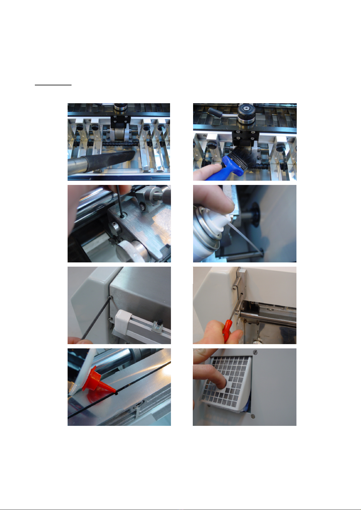
1. Open the safety cover to gain access to the paper feed section. Using a vacuum cleaner to
remove any build-up of dust. (Fig .1)
8
7
6
5
4
3
1
2

10 - Spedo 2600 Service Manual SP 007 011
Operator Maintenance procedures (continued)
2. With a soft hair bush, remove any compressed paper dust build-up on the drive wheel.
(Fig. 2) If the build-up of dust is so compressed that a soft hair brush alone will not
remove it, you can use a soft grade brass wire brush. NOTE: Do not use a steel wire
bush or any form of abrasive to clean the drive wheel surface.
3. Remove, and lubricate the edge trimmer oil wicks (one per edge trimmer) with light
machine oil. Refit the oil wicks once oil has soaked in. (Fig. 3) NOTE: Do not over oil
the wicks as this may cause marks on the edges of the forms.
4. Lubricate the drive wheel drive shaft bush. We recommend using light machine oil, in an
aerosol form to ease application. (Fig. 4)
5. Remove the blade guard. (Fig. 5) WARNING Exposed blades proceed with caution.
6. Loosen the two grub screws which retain the pressure head mount plate, (Fig. 6) and lift
the assembly clear of the machine.
7. Apply only one drop of light machine oil into each of the oil channels on the blade guide.
(Fig. 7) NOTE: Do not over oil the guide as this may cause marks on the end of the
forms.
8. Remove the fan filter, (Fig. 8) and clean using a vacuum cleaner. WARNING Do not
immerse the filter in water to clean.
11 - Spedo 2600 Service Manual SP 007 011
Service Engineer's Procedures
To prevent excess component wear and damage to motors and drivers, the tasks shown in the
service table must be completed at each 5,000,000 cycle interval
Please read this complete section before starting.
WARNING The machine must be isolated from its power supply before starting any
maintenance procedure
Section 1a – Edge Trimmer Unit removal
1
2
3
4
5
6
7
8
12 - Spedo 2600 Service Manual SP 007 011
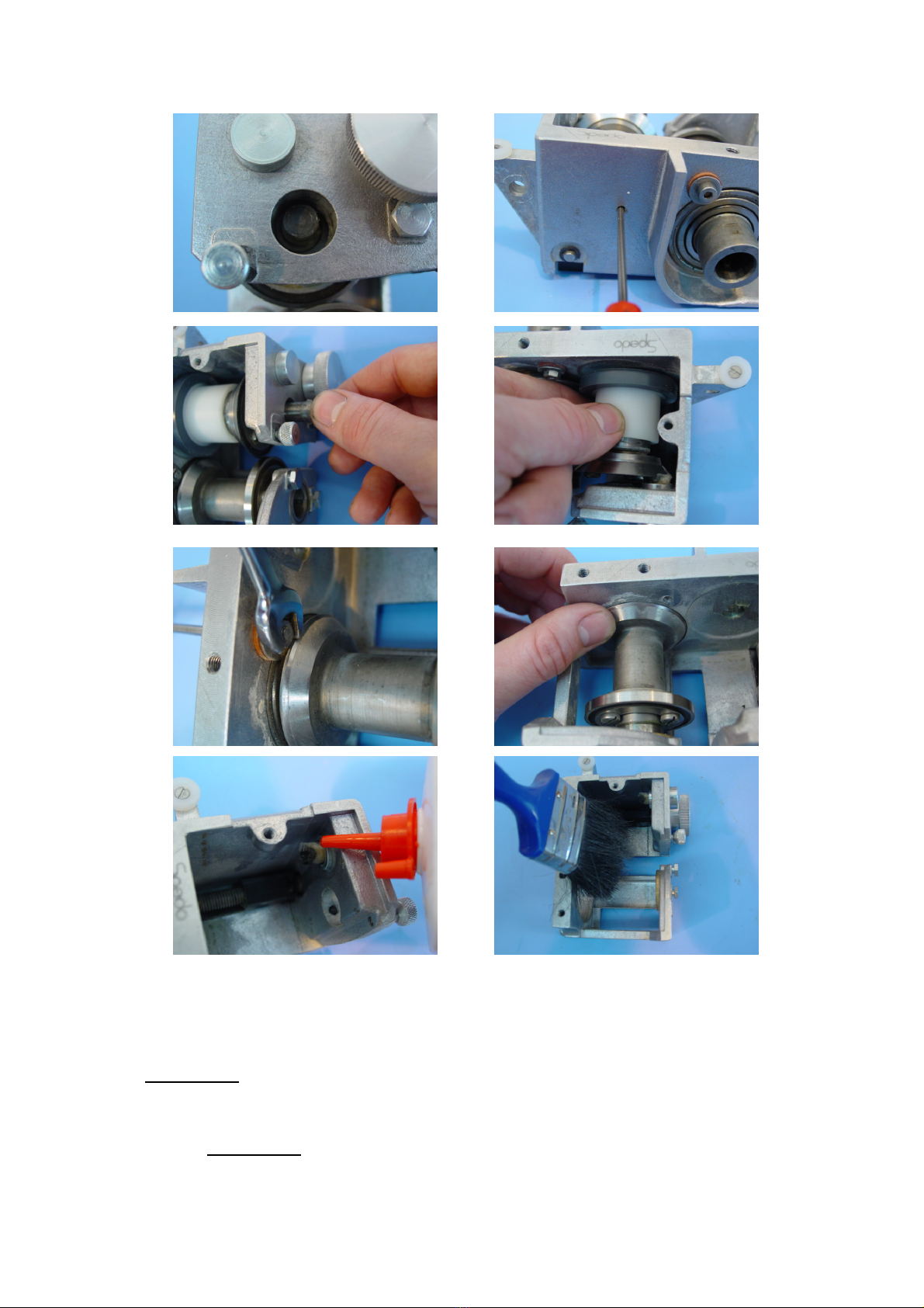
Section 1a – Edge Trimmer Unit removal (continued)
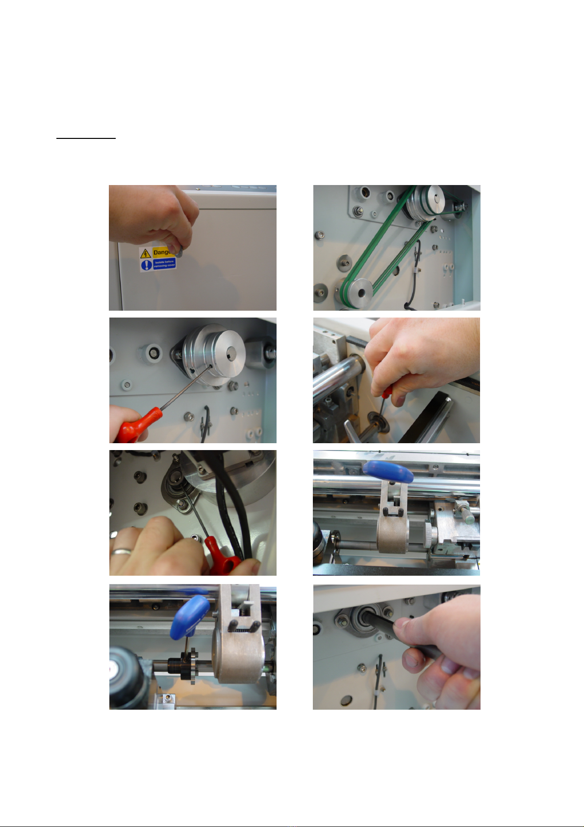
1. Remove the outer service door. (Fig. 1)
2. Remove the edge trimmer and kick-out roller drive belts (Fig. 2) and pulleys. (Fig. 3)
3. Loosen the grub screw that retains the edge trimmer shaft into the bearings, there is one
at each end of the shaft. (Fig. 4 & 5)
4. Loosen the grub screw that holds the centre cutter arm, slide the arm to one side allowing
clear access to the lower centre cutter hub. (Fig. 6)
5. Loosen the lower centre cutter hub and slide it clear of its support. (Fig. 7)
6. Carefully remove the edge trimmer drive shaft by gently pulling it towards you. The
edge trimmer units and centre cutter lower hub will need to be supported during this
process. Failure to do so may result in the shaft becoming difficult to remove. (Fig. 8)
WARNING Do not force the drive shaft in either direction. If the shaft is proving
difficult to remove, examine the shaft for damage.
Section 1b – Edge Trimmer Unit strip
1
2
3
4
5
6
13 - Spedo 2600 Service Manual SP 007 011
Section 1b – Edge Trimmer Unit strip (continued)
1. Remove the paper guide by loosening the knurled screw and push the guide out from the
rear. (Fig. 1 & 2)
2. Remove the paper deflector plate to expose the edge trimmer blades. (Fig. 3 & 4)
WARNING Even blades that have been used may still be sharp so proceed with
caution.
3. Loosen the grub screw in the front of the edge trimmer which retains the eccentric bush.
(Fig. 5) WARNING The eccentric bush is spring loaded so you must keep your thumb
over the top while removing the grub screw.(Fig. 6)
7
8
9
10
11
12
13
14

14 - Spedo 2600 Service Manual SP 007 011
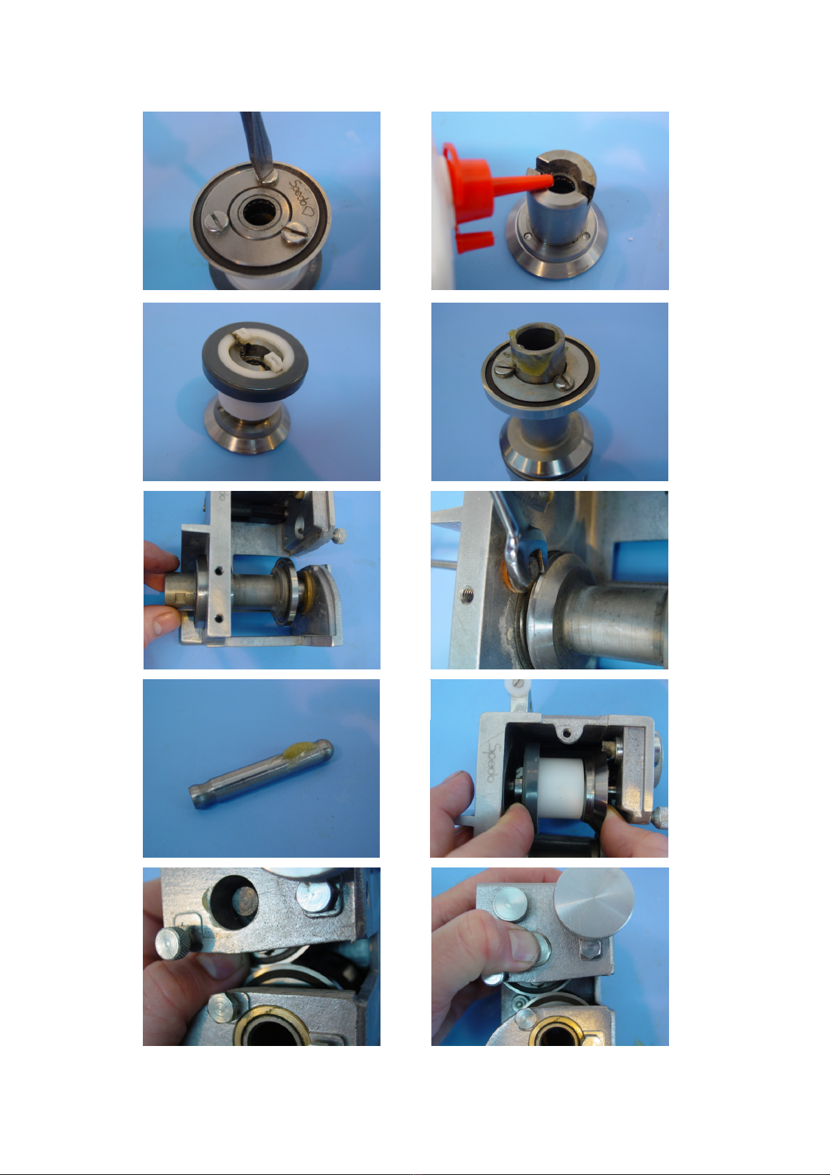
Section 1b – Edge Trimmer Unit strip (continued)
4. Once the eccentric bush and spring have been removed, you are able to see the upper hub
axle. (Fig. 7)
5. The axle is removed by pushing it out from the opposite end. You may have to apply a
small amount of pressure, using a pin punch. (Fig. 8)
6. Once the end of the axle is exposed you will be able to remove it from the edge trimmer
unit. (Fig. 9) WARNING The upper hub is no longer retained and may fall out.
7. Carefully remove the upper hub. (Fig. 10)
8. Remove the lower hub retainer and carefully remove the hub. (Fig. 11) You may need to
apply a small amount of pressure to the drive edge of the lower hub. (Fig. 12)
9. Apply a small amount of light machine oil to the blade wick. (Fig. 13)
10. Remove any dust build up in the casting with a soft hair brush, or airline. (Fig. 14)
Section 1c – Edge Trimmer Unit rebuild
1
2
3
4
5
6
15 - Spedo 2600 Service Manual SP 007 011
Section 1c – Edge Trimmer Unit rebuild (continued)
7
8
10
11
12
13
14
15
16
9
16 - Spedo 2600 Service Manual SP 007 011
Section 1c – Edge Trimmer Unit rebuild (continued)
1. Remove the lower edge trimmer blade. (Fig. 1) This blade has two cutting faces. If one face
is good, turn the blade so that the good face is to the inside. (Fig. 2)
2. Remove the friction hub, (Fig. 3) and the pressure springs. (Fig. 4) Then refit the friction
hub, (Fig. 5) this will give you something to hold as you undo the upper edge trimmer
blade. (Fig. 6) WARNING Hold the blade as shown, failing to do so may result in
injury.
3. Replace the upper blade. Always fit a new upper blade if you either turn, or replace the
lower blade (Fig. 7)
4. Apply a small amount of light machine oil to the upper hub wick. (Fig. 8)
5. Refit the springs and friction hub to the upper hub. (Fig. 9)
6. Apply HMP grease to the bearing surface of the lower hub. (Fig. 10)
7. Refit the lower hub and lower hub retainer. (Fig. 11 & 12)
8. Apply HMP grease to the upper hub axle. (Fig. 13)
17
18
19
20
21
22

17 - Spedo 2600 Service Manual SP 007 011
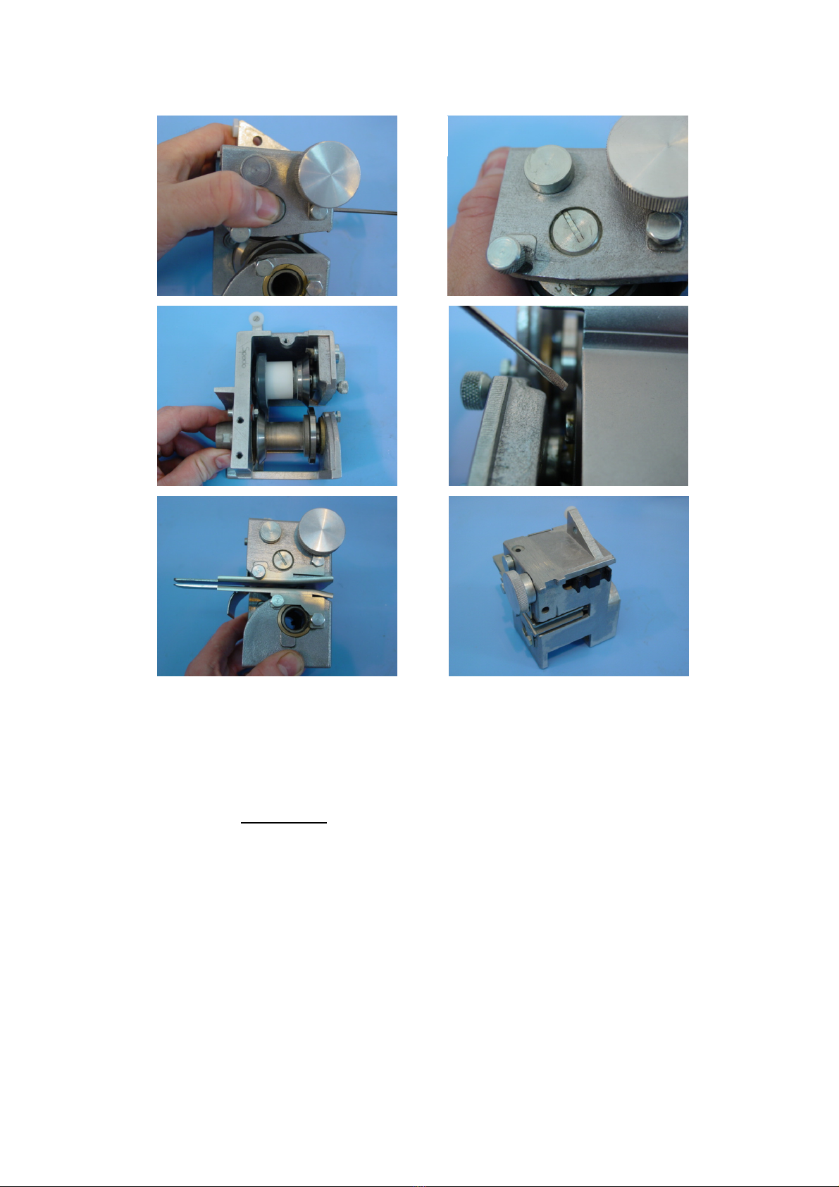
Section 1c – Edge Trimmer Unit rebuild (continued)
9. Compress the upper hub and fit into position within the edge trimmer housing. With the
upper hub still compressed insert the axle. This can be very tricky and may take several
attempts. (Fig. 14) WARNING The upper blade is very sharp. Care must be taken
when refitting the upper hub.
10. With the upper hub still compressed, move the upper hub down behind the lower hub to
create an overlap. (Fig. 15)
11. Refit the eccentric bush and spring. Once the bush is located into the edge trimmer housing,
you can release the upper hub. Keep your thumb over the eccentric bush as the spring will
try to dislodge it. (Fig. 16)
12. With your thumb still positioned over the eccentric bush, tighten into place. (Fig. 17)
13. Loosen the grub screw holding the eccentric bush by approximately ¼ turn. Then with a
screw driver adjust the eccentric bush to the position shown. Retighten the grub screw. The
head of the eccentric bush should now be approximately flush with the side of the edge
trimmer housing. (Fig. 18)
14. Cycle the edge trimmer unit by hand. There should be no binding or stiffness in the
operation. (Fig. 19) WARNING Keep your fingers clear as you cycle the blades.
15. Refit the paper deflector plate. (Fig. 20) NOTE the deflector should be positioned
approximately 1mm from the blade cutting edge.
16. Refit the paper guide. (Fig. 21)
17. The edge trimmer units can now be fitted back into the machine. To refit the edge trimmer
units complete Section 1a ‘Edge Trimmer Shaft Removal’ in reverse order. NOTE: It is
recommended that anti-fret compound is used on the shaft as it is reinserted into the
bearings either end of the drive shaft.
Section 2a – Centre cutter lower hub removal
Please read this complete section before starting.
WARNING The machine must be isolated from its power supply before starting any
maintenance procedure.
1. Remove the lower centre cutter hub by completing Section 1a ‘Edge Trimmer Shaft
Removal’
Section 2b – Centre cutter arm service
1
2
18 - Spedo 2600 Service Manual SP 007 011
Section 2b – Centre cutter arm service (continued)
3
4
5
6
7
8
9
10
11
12

19 - Spedo 2600 Service Manual SP 007 011
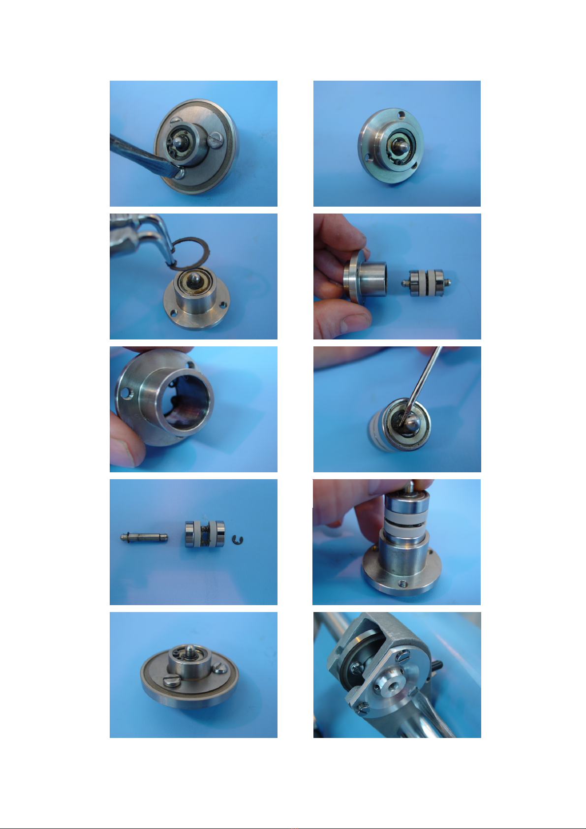
Section 2b – Centre cutter arm service (continued)
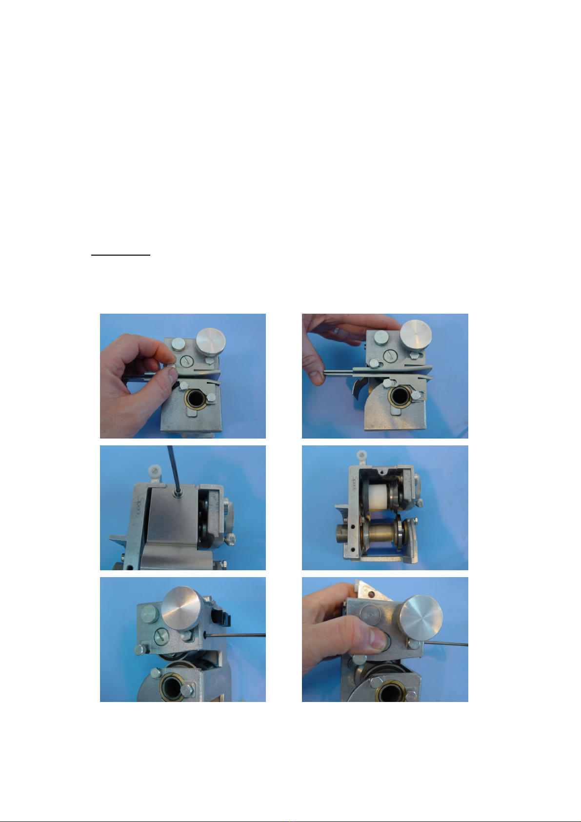
1. Remove the centre cutter adjustment plate. (Fig. 1) WARNING The upper hub is no
longer retained and may fall out.
2. Remove the upper centre cutter hub. (Fig. 2) WARNING Even blades that have been
used may still be sharp so proceed with caution.
3. Remove the centre cutter blade. (Fig. 3 & 4)
4. Remove one of the circlips on the upper centre cutter hub. (Fig. 5) WARNING Safety
goggles must be worn when removing circlips.
5. The bearing assembly should now slide out of the upper centre cutter hub. (Fig. 6)
6. Inspect the condition of the bearing surface on the inside of the upper centre cutter hub. It is
normal for there to be a small number of marks on the bearing surface. However if there are
any deep scores this will affect the centre cutter operation. (Fig. 7)
7. Remove the circlip from the bearing assembly, (Fig. 8) and remove the axle. (Fig. 9) Check
the bearings for signs of wear, then lubricate the springs and axle with HMP grease, and
reassemble into the hub. (Fig. 10)
8. Refit the centre cutter blade. This blade has two cutting faces. If one face is good, turn the
blade so that the good face is on the side that the centre cutter is adjusted to cut on. (Fig. 11)
See Section 2d ‘Set the Centre Cutter’ for instruction on how to change the side the centre
cutter cuts on.
9. Refit the centre cutter adjustment plate. If you haven’t changed any settings on the
adjustment plate, then you will be able to simply refit, without further adjustment. (Fig 12)
Section 2c – Centre cutter lower hub blade change
1
2
3

20 - Spedo 2600 Service Manual SP 007 011
Section 2c – Centre cutter lower hub blade change (continued)
1. Remove the blade from the lower centre cutter hub. Use a cloth to wrap the blade to protect
your hand. (Fig. 1 & 2) WARNING Even blades that have been used may still be sharp
so proceed with caution.
2. Refit the centre cutter blade. This blade has two cutting faces. If one face is good, turn the
blade so that the good face is on the side that the centre cutter is adjusted to cut on. (Fig. 3)
See Section 2d ‘Set the Centre Cutter’ for instruction on how to change the side the centre
cutter cuts on.
Section 2d – Centre cutter arm adjustment
1. To adjust the centre cutter arm to cut on the right side of the lower centre cutter blade. First
loosen the two grub screws marked (Fig. 1). Tighten the rear grub screw all the way in then
loosen by ¼ turn. Then retighten the two marked grub screws. This will angle the blade as
shown in Fig. 2.
2. To adjust the centre cutter arm to cut on the left side of the lower centre cutter blade. First
loosen the two grub screws marked (Fig. 3). Tighten the top grub screw all the way in then
loosen by ¼ turn. Then retighten the two marked grub screws. This will angle the blade as
shown in Fig. 4.
1
2
3
4
Other manuals for 2600
1
Table of contents
Other Spedo Cutter manuals


