KTM STREAMLINE SL-IV 100 Operation manual

Printed: 02/14/05
STREAMLINE HIGH PRESSURE
WATERJET PUMP
OPERATION and SERVICE MANUAL
SL-IV 100 hp
200-208v/3/50-60
Manual No. 05148267 Rev. 0
Original: August 2001
05148283

NOTICE
This document contains subject matter in which KMT Waterjet
Systems has proprietary rights. Recipients of this document shall
not duplicate, use, or disclose information contained herein, in
whole or in part, for other than the purpose for which this
manual was provided.
KMT Waterjet Systems believes the information described in this
manual to be accurate and reliable. Much care has been taken in
its preparation, however, the Company cannot accept any
responsibility, financial or otherwise, for any consequences
arising out of the use of this material. The information contained
herein is subject to change, and revisions may be issued to advise
of such changes and/or additions
KMT WATERJET SYSTEMS 2003
SL-IV/100
Version 1.0
December 1999
480 V 05113287
480 V 05121041 Proportional Control
100S SL-IV 480/400V
KMT Waterjet Systems
635 West 12th Street P.O.Box 231
Baxter Springs, Kansas 66713
Tel. (620) 856-2151
Tel. (800) 826-9274
FAX (620) 856-5050
05119516.doc

TABLE OF CONTENTS
SECTION 1 INTRODUCTION
1 SL-IV100hp Waterjet Pump General Information 1-1
1.1 Physical Description 1-1
1.1.1 Standard Equipment 1-2
1.2 Functional Description 1-3
1.2.1 Functional Features 1-3
1.3 Worldwide Product Support 1-4
1.3.1 Service Department 1-4
1.3.2 Spare Parts 1-4
1.3.3Questionnaire 1-5
1.4 Safety 1-7
1.4.1 Labels and Abbreviations 1-7
1.4.2 Safety Procedures 1-9
1.4.3 High Pressure (HP) Piping Safety 1-11
1.4.4 Emergency Medical Treatment 1-12
SECTION 2 INSTALLATION
2Installation 2-1
2.1 Installation Overview 2-1
2.1.1BuyerObligations 2-2
2.1.2 Seller Obligations 2-3
2.2 Installation Requirements (Utilities) 2-4
2.2.1 Equipment Location/Environment 2-4
2.2.2 Service Connections 2-5
2.2.3 Tools and Equipment 2-6
SECTION 3 OPERATION
3Operation 3-1
3.1 Operation Overview 3-1
3.2OperatorConsole 3-2
3.2.1 Component Description 3-2
3.2.2 Operating Procedures 3-4
3.2.3RemoteOperation 3-5
3.3 Initial Start-Up Procedure 3-5

3.3.1 Initial Pump Start Up Checks 3-6
3.3.2 Pump Operation 3-8
3.4 Shutdown Procedure 3-10
3.4.1 Normal Shutdown Procedure 3-10
3.4.2 Emergency Shutdown Procedure 3-10
3.4.3 Remote E-Stop Provisions 3-10
3.5 Fault Messages Overview 3-11
3.5.1 Water Supply Valve Reset 3-11
3.5.2 High Oil Temperature Shutdown 3-11
3.5.3 Low Oil Level Shutdown 3-12
3.5.4 High Booster Temperature Shutdown 3-12
3.5.5 High Pressure Leak Warning 3-13
3.5.6 Cutting Water Supply 3-14
3.5.7 Idle Shutdown 3-14
3.5.8 High Pressure Water Transducer 3-14
SECTION 4 MAINTENANCE
4Maintenance 4-1
4.1 Scheduled Maintenance 4-3
4.2 General Maintenance 4-4
4.3 Service Log Data 4-6
SECTION 5 TROUBLESHOOTING
5Troubleshooting 5-1
SECTION 6 LOW PRESSURE WATER SYSTEM
6 Low Pressure Water System 6-1
6.1 Oil Cooling Water Supply 6-1
6.2 Cutting Water Supply 6-2
6.2.1 Normal Operating Condition 6-2
6.2.2Operation 6-3
6.2.3 Boost Pump Pressure Adjustment 6-4
6.2.4 Low Pressure System Protection 6-4
6.3 Maintenance Overview 6-5
6.3.1 Water Filter Service 6-6
6.3.2 Boost Pump 6-7

SECTION 7 HIGH PRESSURE WATER SYSTEM
7 High Pressure (HP) Water 7-1
7.1 Components 7-1
7.2 Intensifier Disassembly and Reassembly 7-2
7.2.1 HP & LP Water Piping 7-3
7.2.2 HP Sealing Head 7-4
7.2.3HPCylinder 7-6
7.2.4 Hydraulic Seal Cartridge & Plunger 7-8
7.2.5 Hydraulic Cylinder Head and Hydraulic Piston 7-10
7.3 Intensifier Subassemblies Inspection and Repair 7-12
7.3.1 Discharge HP Check Valve 7-13
7.3.2 Inlet Check Valve 7-15
7.3.3 Sealing Head 7-16
7.3.4HPCylinder 7-17
7.3.5 Plunger 7-18
7.3.6 Hydraulic Seal Cartridge 7-19
7.3.7 Hydraulic Piston 7-21
7.3.8 Hydraulic Cylinder 7-23
7.4 HP Dump Valve 7-24
7.5 HP Attenuators 7-24
SECTION 8 ELECTRICAL SYSTEM
8ElectricalSystem 8-1
8.1 Electrical Overview 8-1
8.1.1 Motor Starter Circuit 8-1
8.1.2 Control Circuits and Logic 8-2
8.1.3Operation 8-3
8.2 Maintenance Overview 8-5
8.2.1 Proximity Switch Service 8-5
8.2.2 Optical Relay Switch Service 8-6
SECTION 9 HYDRAULIC SYSTEM
9HydraulicSystem 9-1
9.1 Overview 9-1
9.1.1 Features 9-2

9.1.2 Components 9-3
9.2Operation 9-4
9.2.1 Hydraulic Pressure Adjustment 9-4
9.2.2 Hydraulic System Pressure Protection 9-5
9.3 Motor/Hydraulic Service Maintenance 9-6
9.3.1 Motor Service 9-7
9.3.2ManifoldService 9-7
SECTION 10 RECIRCULATION SYSTEM
10 Recirculation System 10-1
10.1 Components 10-1
10.2 Operation 10-2
10.3 System Pressure Protection 10-3
10.4 Maintenance Overview 10-4
SECTION 11 SPECIFICATIONS
11 Specifications 11-1
11.1 Equipment Specifications 11-1
11.2 Torque Specifications 11-3
11.3 Cutting Water Specifications 11-4
11.4 Cooling Water Specifications 11-5
11.5 Orifice Support Capacity 11-5
SECTION 12 PARTS LIST
12 Parts List 12-1

SECTION 1
INTRODUCTION
Jan 2001 Page 1-1 05114566
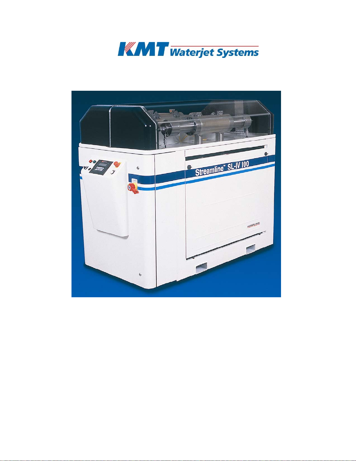
1SL-IV 100hp Waterjet Pump General Information
The Streamline SL-IV 100hp Waterjet Pump, maintains the level of component
reliability and ease of installation and maintenance that have made the KMT
Waterjet Streamline waterjet pumps the standard of the industry for both water
and Hydrobrasive™ applications.
The SL-IV 100hp Waterjet Pump uses low pressure water, which meets certain
quality requirements, and increases the pressure up to 3,800 bar (55,000 psi)
for ultra-high–pressure waterjet cutting, hydrobrasive cutting, cleaning, surface
preparation, etc.
This manual provides information for installation, operation, and maintenance
of the SL-IV100hp Waterjet Pump.
1.1 Physical Description
The 100hp waterjet pump is equipped with two simultaneously operating
hydraulic intensifiers, two high pressure attenuators, a motor/hydraulic pump
assembly, an electric starter panel, control sensors, solenoids and logic, control
interface panel, a low pressure water boost pump, and a low pressure water
filter.
It is enclosed in a frame with the dimensions of 77.75” length, 36.0” width, and
56.19” height. The high pressure system is conveniently mounted on a drip
pan. All service components are easily accessible from at least two sides
simplifying maintenance. The entire high pressure system can be removed from
the rest of the unit quickly for maintenance and serviceability.

SECTION 1
INTRODUCTION
Jan 2001 Page 1-2 05114566
1.1.1 Standard Equipment
Following is an overview of the standard equipment for the SL-IV100hp Waterjet
Pump:
•Variable displacement, pressure compensated hydraulic pump
•Water pressure boost and filtration system with 10-micron double-length
filter
•High efficiency heat exchanger in independent recirculation pump circuit
•Stand-alone unit with built-in Wye Delta motor starter
•High pressure safety dump valve
•Dual pressure compensator
•2 High pressure attenuators
•Microprocessor control with diagnostic capability
•Water inlet shut-off valve
•Boost pump
•Separate water and oil drip pans
•Electrical remote control interface

SECTION 1
INTRODUCTION
Jan 2001 Page 1-3 05114566
1.2 Functional Description
The SL-IV100hp Waterjet Pump meets the automotive and industrial markets
needs of low to high volume production of water jet pumps. The maximum HP
water pressure is limited by a hydraulic relief valve that is certified and sealed
by TUV. No HP rupture disk is required.
The HP intensifier is a reciprocating, double-ended hydraulic operated,
electrically shifted hydraulic piston type. The HP intensifiers work in parallel,
while the two HP attenuators reduce the routine fluctuations in the HP water
pressure signal. The compression ratio is 20:1 with a maximum hydraulic
pressure set at
3,100 psi.
The recirculation hydraulic loop for cooling and filtering oil runs continuously
whenever the motor is running.
1.2.1 Functional Features
Following is a list of SL-IV100hp Waterjet Pump features:
•4,150 bar (60,000 psi) design pressure
•3,800 bar (55,000 psi) operating pressure
•Electronic reversing
•24vdc safety control
•Standard high pressure water leak detection
•Standard dual pressure control facilitates hole piercing and kiss cut
applications
•Exclusive long slow stroke
•Cartridge type hydraulic seal
•Low pressure water boost pump and filtration
•Reduced cooling water requirements
•Choice of English, German, Spanish, French, Swedish and Italian readouts
as standard
•Meets CE requirements

SECTION 1
INTRODUCTION
Jan 2001 Page 1-4 05114566
1.3 Worldwide Product Support
The KMT waterjet Service Department serves the customer, by providing:
•Supervision of equipment installation, start up, and training for the number
of days specified in the quotation, and per approved project. Additional time
requested will be invoiced on a per diem basis, plus travel and normal living
expenses.
•Field Services: on-site technical support is available on request. These
services are invoiced on a per diem basis, plus travel, and normal living
expenses.
•Technical Assistance: the Service Department is available for technical
assistance by phone.
•Training: the Service Department conducts periodic training sessions at
KMT Waterjet designated training locations. On-site training is also
available.
1.3.1 Service Department
To contact the KMT Waterjet Service Department:
USA: Service Manager Europe: Technical Manager
KMT KMT Waterjet Systems GmbH
Waterjet Systems Wasserstrahl–Schneidetechnik
635 West 12th Street Auf der Laukert 11
Baxter Springs, KS 66713 D–61231 Bad Nauheim
USA Germany
Phone:(620) 856–2151 Phone:49–(0)6032–997–117
Fax: (620) 856–5050 Fax: 49–(0)6032–997–270
1.3.2 Spare Parts
KMT waterjet maintains a well stocked Spare Parts Department staffed by well
trained knowledgeable personnel. Emergency shipment is available.
Contact the Service Department of KMT Waterjet.
1.3.3 Questionnaire
The following equipment and service manual questionnaire will provide
information to allow us to serve you better. Please complete them at your
convenience and return to the applicable Service Department as shown above.

SECTION 1
INTRODUCTION
Jan 2001 Page 1-5 05114566
EQUIPMENT AND SERVICE MANUAL QUESTIONNAIRE
We have just installed a new SL-IV100hp Waterjet Pump at your location. We
are interested in your initial impressions of the unit and its installation. Please
take a few moments and answer the following questions.
1. General Appearance
Was unit received in good condition?
Comments:
Yes
No
2. Is the unit a convenient size?
Yes No
3. Controls
a. Are the controls user friendly?
b. Is the unit easy to operate?
Comments:
Yes
Yes
No
No
4. Performance
a. Does the unit perform smoothly and meet your
expectations?
b. Does the unit run quietly?
Comments:
Yes
Yes
No
No
5. Did installation and start-up go smoothly?
Comments:
Yes No
6. What feature(s) do you consider the most significant with this
unit?
Quiet Operation
Appearance
Performance (Operation)
Repair/Maintenance

SECTION 1
INTRODUCTION
Jan 2001 Page 1-6 05114566
Other
7. What areas need improvement?
Appearance
Servicability
Performance ________
Other

SECTION 1
INTRODUCTION
Jan 2001 Page 1-7 05114566
Manual Organization
1. Does the table of contents help you find topics easily?
Comments:
Yes No
2. Is the information well organized?
Comments:
Yes No
3. Is the page layout suitable for the material being presented?
Comments:
Yes No
Graphics
1. How do you rate the quality and quantity of the
photos/illustrations?
Comments:
Yes No
Text
1. Does the information in the manual adequately explain how to
operate and service the equipment?
Comments:
Yes No
2. Are there paragraphs or procedures you feel need clarification?
Please identify them by page number and add your comments.
Comments:
Yes No
3. Is there anything you would add or delete from the manual to
make it more useful?
Comments:
Yes No
4. Is there any information that should receive more emphasis?
Comments:
Yes No

SECTION 1
INTRODUCTION
Jan 2001 Page 1-8 05114566
Name: Title:
Company
Address:

SECTION 1
INTRODUCTION
Jan 2001 Page 1-9 05114566
1.4 Safety
Safety procedures and safe practices must be followed during installation,
operation, and maintenance of the waterjet pump. In this section we have
provided label and sign descriptions used in this manual, as well as
recommended safety procedures.
1.4.1 Labels and Abbreviations
The following describes hazard classifications of the waterjet pump.
Indicates the presence of a hazard, which can cause
personal injury, or property damage if the caution
instruction is ignored.
Indicates the presence of a hazard, which can cause
severe personal injury, death, or substantial property
damage if the warning instruction is ignored.
High pressure waterjet can cause eye injury. Wear eye
protection when operating or working near machine.
Hazardous noise can cause hearing loss.
Wear ear protection when operating or working near
machine.
Hazardous voltage within can cause injury or death.
Disconnect and lockout main power before opening
cabinet.
Malfunction
Hydraulic Intensifiers
Pressure Control
High Pressure
Low Pressure
Start/Control Power On
Stop
Run
!
W
ARNING
!
CAUTION
!

SECTION 1
INTRODUCTION
Jan 2001 Page 1-10 05114566
Rear of Waterjet Pump
•HP Water "OUT"
•Plant Air "IN"
•Cooling Water "IN"
•Cooling Water "OUT"
•Cutting Water "IN"
•Drain

SECTION 1
INTRODUCTION
Jan 2001 Page 1-11 05114566
1.4.2 Safety Procedures
Safety procedures must be observed while working on the pump, or any high
pressure part of the installation. Service should only be performed by
qualified personnel.
•The high pressure water, 3,800 bar (55,000 psi) in waterjet cutting systems
should not be a cause for concern. Users must have due respect for these
pressures and use proper SAFETY PROCEDURES and SAFE WORK HABITS.
•Everyone associated with the waterjet cutting system must realize that the
force of the waterjet cutting stream can penetrate many dense or strong
materials.
•Keep all untrained people away from the waterjet cutting area. Use barriers
or partitions if needed.
•Safety glasses must be worn at all times in the waterjet cutting area.
•All EMERGENCY STOP buttons must be checked periodically. The normal
operating position is pulled out.
•To check: turn on power and activate the EMERGENCY STOP buttons by
pushing them in to see if the power goes off. Each device should be checked
on a specified schedule. Each time the device is checked, it must function or
be replaced before operating the system.
•Apply High Purity Goop (P/N 10084440) to all threaded high pressure
connections. All tubing, fittings and bolted connections should be torqued to
recommended values. Do NOT attempt to tighten or loosen a HP water fitting
when the circuit is pressurized, see High Pressure (HP) Piping Safety.
•All high pressure leaks must be repaired immediately.
•Inspect all equipment on a scheduled basis.
•Before performing any maintenance on the unit, MECHANICALLY LOCK
THE MAIN CONTROL POWER OFF, and assure the high pressure has been
bled off.

SECTION 1
INTRODUCTION
Jan 2001 Page 1-12 05114566
Never do any work on the unit without making sure the
electrical panel disconnect is locked out with a padlock in
the OFF position.
Never work on any high pressure component, or loosen any
high pressure fittings without first bleeding the system and
assuring there is no high pressure water present.
Make sure the safety devices are operational. To panic stop
the pump and bleed the high pressure, the EMERGENCY
STOP buttons must be pushed in. The system pressure
dump valves must be open.
Do not attempt to touch or be exposed to high pressure
water. The high pressure water will penetrate all parts of
human body without exception.
The liquid stream or material ejected by these extreme
pressures can injure or kill.
W
ARNING
!
W
ARNING
!
W
ARNING
!
W
ARNING
!
W
ARNING
!

SECTION 1
INTRODUCTION
Jan 2001 Page 1-13 05114566
1.4.3 High Pressure (HP) Piping Safety
High pressure piping must be installed without torsional or bending stresses.
Proper supports and guides must be provided. 9/16” outside diameter HP
tubing and fittings are recommended between the pump and the cutting
station. This large tubing size will reduce vibration, strain and motion between
the pump piping and the cutting area. The larger piping diameter also reduces
pressure drop, and pressure pulsation.
Do not try to repair a leak in a HP water fitting when it is
pressurized. Always shut off the power and bleed the HP
water before doing maintenance on HP components. Weep
holes are provided to release HP water if leakage occurs at a
sealing surface. If a fitting is loosened with HP water
present, a jet of HP water will exit the nearest weep hole
with possible hazardous results.
Use extreme caution when handling high pressure
equipment. Possible failure from fatigue cracking or over-
pressurization can result in a hazardous high pressure
leak, or component failure.
A flexible ¼” HP tube (whip) is frequently used on the
cutting system to allow cutting nozzle movement. Supports
and guides for the whip must be used, anti-vibration
fittings and proper support must be provided to prevent
failures from external loads (non-water related stresses).
When tightening or loosening HP connections, always use a
supporting wrench to avoid bending forces or stress on the
connection. Do not exceed recommended torque values
High pressure piping and fittings designed to 4,100 bar
(60,000 psi) must always be used. Failure to do so may lead
to catastrophic component failure, which can cause
equipment damage, injury or even death.
W
ARNING
!
W
ARNING
!
W
ARNING
!
W
ARNING
!
W
ARNING
!

SECTION 1
INTRODUCTION
Jan 2001 Page 1-14 05114566
1.4.4 Emergency Medical Treatment
An information card to aid treating a waterjet injury is included in the binder of
each manual. The card is shown below. Contact the address shown for
additional cards.
(Front Side)
Medical Alert
This card is to be carried by personnel working with high pressure
Waterjet equipment. Obtain medical treatment
immediately for ANY high pressure waterjet injuries.
KMT WATERJET SYSTEMS
635 West. 12th Street
Baxter Springs, KS. 66713
(620) 856-2151
(Back Side)
This person has been working with water jetting at pressures to
55,000 psi (374MPa, 3740 bar, 3867 Kg/cm2) with a jet velocity
of 3,000 fps (914 mps). Foreign material (sand) may have been
injected with water. Unusual infections with microaerophilic
organisms occurring at lower temperatures have been reported,
such as gram negative pathogens as are found in sewage.
Bacterial swabs and blood cultures may therefore be helpful.
This injury must be treated as an acute surgical emergency and
be evaluated by a qualified surgeon. Circulation may be
compromised, therefore, DO NOT APPLY HEAT TO
INJURED PART. For first aid: (1) Elevate injured part (2)
Antibiotics (3) Keep injured person NPO.
Table of contents
Other KTM Industrial Equipment manuals
Popular Industrial Equipment manuals by other brands

Maretron
Maretron CLM100 user manual

Schatten Design
Schatten Design Model B Assembly instructions

Piranha
Piranha MegaFab P-110 Instruction And Repair Parts Manual

TEM
TEM PhaseLock manual

Flowserve
Flowserve Limitorque HBC Series User instructions

MDT Technologies
MDT Technologies RF-LK001.03 Technical manual