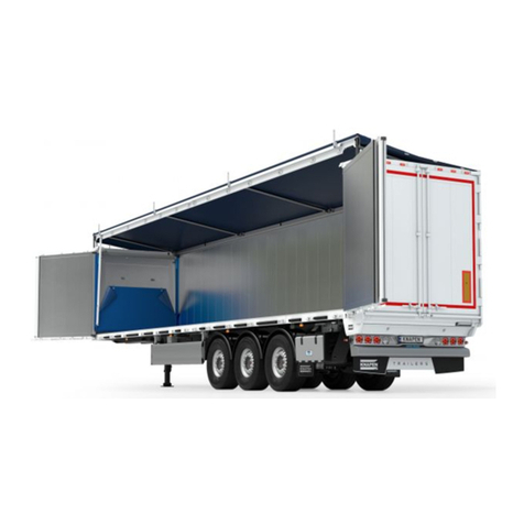
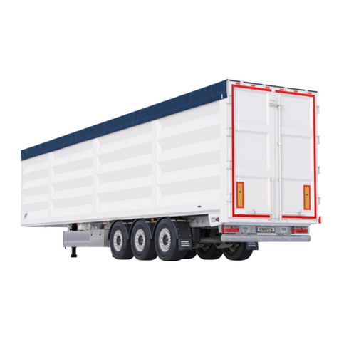
Knapen Trailers K200 User manual

USERS
MANUAL
Knapen Trailers
EN
knapen-trailers.eu
User Manual EN | v201906

2
Table of Contents
1 Introduction 5
1.1 General 5
1.2 Applicationofamovingoortrailer 6
1.3 Symbols in this manual 6
2 Vehicle identication 7
2.1 Trailer position indications 7
3 Safety 9
3.1 General safety rules 9
3.2 First check after receiving the trailer 9
3.3 Standard visual inspection before driving off 10
3.4 Safety instructions 11
3.5 Personal protective equipment 12
4 General use of trailer 13
4.1 Coupling 13
4.2 Uncoupling 14
4.3 Landing legs 15
4.4 Wheel wedges 16
4.5 Mudguards 16
4.6 Connectors 17
4.7 Control box air suspension/lift axle 19
4.9 Lift axle (option) 24
4.10 Brakes 25
4.11 Lighting 26
4.12 Toolbox / storage box 27
4.13 Self steering axle (option) 27
4.14 Towing eye (option) 28
5 Use moving oor trailer 29
5.1 General operation 29
5.2 Loading of bulk goods 34
5.3 Unloading of bulk goods 35
5.4 Loading pallets 36
5.5 Floor sheet (option) 38

3
User Manual EN | v201906
5.6 Operatingthemovingoor(Bcontrol) 41
5.7 Operatingthemovingoor(E-operation) 42
5.8 Use of the Knapen Trailers remote control 43
5.9 Use of the bars and upper beam 46
5.10 Use of sheeting systems 48
5.11 PowerSheet® (option) 51
5.12 Sidewall protection sheet (option) 53
6 Maintenance and cleaning 54
6.1 Trailer maintenance instructions 54
6.2 Cleaning the lighting system 57
6.3 Cleaning the outside 57
6.4 Pneumatic rear door locking device 58
6.5 Check compressed air 59
6.6 Cleaning the top rail 59
6.7 Cleaningthemovingoor 60
6.8 Maintenance of tyres and rims 62
6.9 Maintenance PowerSheet®(option) 64
6.10 Maintenance hydraulic system 64
7 Troubleshooting 65
7.1 Troubleshootingmovingoor 65
7.2 EmergencycontrolB-control 66
7.3 EmergencycontrolE-control 67
7.4 Troubleshooting PowerSheet 68
7.5 Troubleshooting Knapen Trailers remote control 72
8 Warranty 75
9 Technical data 76
9.1 Landing legs 76
9.2 Kingpin 76
9.3 Floor system 77

4

5
User Manual EN | v201906
1 Introduction
1.1 General
Dear driver,
Congratulationsonthepurchaseofyournewmovingoortrailer:Anindispensabletoolinyourdailywork.Our
greatest concern is with your safety. This manual plays an important role in this. Before using the trailer for the
rsttime,readtheusermanualcarefullytopreventaccidentsand/orseriousdamage.Ifyouhaveanyquestionsor
comments, please contact us via www.knapen-trailers.eu/contact.
Soonyouwillunloadwithyourtrailerfortheveryrsttime:Enjoythisspecialmoment!
#KnapenUnloading
Wewishyoumanysafekilometres!
Kind regards,
Knapen Trailers

6
1 Introduction
1.2 Application of a moving oor trailer
The Knapen Trailers moving oor is exceptionally suited for the transport of bulk goods.
With a moving oor trailer, you can transport the following products:
• Agricultural products
• Wood products
• Waste (household)
• Metal waste
• Pallets, big bags
• Paper waste/rolls bales
A trailer tted with a roll-up sheet can, among others, transport the following products:
• Glass
• Gravel
• Ores
• Sharp sand
• Fruit & Vegetables
• Other abrasive materials
Materials that may NOT automatically be transported:
• Abrasive materials with low grain size
• (Greasy) substances that can harden during transport.
• Materialsthataremutuallysubjecttogalvaniccorrosion(e.gbetweencopperandaluminium)
ampliedbythepresenceofmoisture.
When transporting these product categories, there is a risk of the oor planks getting stuck. In this case,
the moving oor must be completely dismounted. This is not covered by the warranty.
The oor is not suited for heavy point loads. A oor load can damage the oor planks and guides.
Point loads also have an effect on wear and tear or damage to the side wall.
For loading with a forklift or pallet truck, we refer to chapter 5.4
Forspecicquestionsorincaseofdoubtregardingtheproducttobetransported,weadviseyoutocontactyour
Knapen Trailers representative.
1.3 Symbols in this manual
Itisveryimportantthateveryonewhooperatesthetrailerreadsthemanualcarefully!
Theinstructionsinthismanualareessentialforusingyourtrailersafely.Inaddition,followingtheregulations
contributes to a longer lifespan of your trailer; Lowest Cost of Ownership.
Thismanualusesvarioussymbols:
Symbol Description
A safety instruction follows this symbol. Failure to follow this instruction correctly may result in
damagetoyourtrailer,injury,andinsomecasesdeath.
Additional information follows this symbol.
For example, a link to another document or a useful tip.
Reference to maintenance and/or cleaning
Reference in case of malfunctions

7
User Manual EN | v201906
2 Vehicle identication
2.1 Trailer position indications
NO Description Chapter
1 Type plate trailer
2 Landing legs / Type plate 4.3
3 Floor system / Type plate 5.1
4Controlvalveoorsystem
5 Axles / Type plate
6 Safety markings sticker 3.4
7 Kingpin plate/kingpin plate 4.1
8 Sheet stick
9 Wabco sticker 4.8
10 VINnumber
Positions may be different, depending on type and conguration
8
10
5
1
6
9
73
2
4
DATUM :
ORDERNUMMER :
KENMERK KLANT :
KLANTNAAM :
CONTACTPERSOON :
ORDERBEGELEIDER :
ONDERWERP :
MATERIAAL :
AANTAL :
AFMETINGEN :
KLEUREN :
BIJZONDERHEDEN :
NAAM :
DATUM :
Wilt u dit ontwerp z.s.m. terugzenden i.v.m. productieplanning en levertijd.
Akkoord Akkoord na correctie Nieuwe proef
Ekkersrijt201 0, 5692BA Son t: +31 (0) 499 - 49 61 81 f : +31(0) 499 - 49 61 82 e: info@dele tterspecialist.nl i: www.deletterspecialist.nl
07-06-2016
014236-002
-
Knapen Trailers BV
Mevr. N Zegers
Sandra Joosten
Sticker ‘30112629’
Avery 735 Silver Metallic vzv polymeer glans laminaat
1
275x141 mm
6/0: Process Black, PMS 2955 blauw, PMS process Cyan, PMS 485 rood,
PMS 123 geel, wit
-
Let op controle van opmaak, teksten en kleuren. Uw akkoord is bindend. Gelieve dit document rechtsonder ondertekend retour te zenden.Schaal 1:1
10
9
KNAPEN SERVICE BV
THE NETHERLANDS TEL: +31 (0)493 320 330
TEL: +31 (0)493 326 666
TYPGENEHMIGUNGSNR.
FAHRGESTELLNR.
LÄNDERCODIERUNG NL
GESAMTMASSE
42000 kg 42000 kg
KUPPLUNGSDRUCK
0-
15000 kg 0- 15000 kg
ACHSLAST MAX.
1-
9000 kg T 11- 9000 kg T 1
2-
9000 kg T 12- 9000 kg T 1
3-
9000 kg T 13- 9000 kg T 1
4- kg T 4- kg T
K200
BAUJAHR 2016
PO: 0
TYPE
TYP
YEAR OF CONSTRUCTION
WWW.KNAPEN-TRAILERS.EU
0
KNAPEN TRAILERS BV
TYPE-APPROVAL NO.
e4*2007/46*0302
IDEN TIFICATION NO.
XPNKAC20020120002
COUNTRY CODE
TOTAL MASS
KING PIN PRESSURE
AXLE MASS MAX.
1
6

8
2 Vehicle identication
NO Description Chapter
11 Electric/air connectors 4.6
12 Hydraulic connectors 4.6
13 Key for roof sheet 5.8
14 Platform 5.8
15 Roof sheet
16 Roof sheet support
17 Strap
18 Side guard
19 Receiver remote control 5.7
20 Toolbox/storage box 4.12
21 Control box air suspension 4.7
22 Operation pneumatic rear door locking device 5.1.6
23 Movable bulk head 5.1.2
24 Bars
25 Ladder
26 Protection plate
27 Pneumatic door locking device 5.1.6
28 Door lock 5.1.6
29 Pull-outladder 5.1.5
11
24
23
15
12 13 14
17
18
19
20
21
22
28
26
29
27
25
right
left
front
back
16

9
User Manual EN | v201906
3 Safety
Read this chapter carefully prior to using the trailer.
Always apply the following points of attention in the daily use of the trailer!
3.1 General safety rules
Do not Do
Standbehindthetrailerwhiletheoorinoperation(see5.1.7). x
Beunderthetrailerwhilethemovingoorisinoperation. x
Standontopofthetrailerwhilethemovingoorisinoperation. x
Enterthetrailerwhilethemovingoorisinoperation. x
Leavethetrailerunattendedwhilethemovingoorisinoperation. x
Block or bridge the emergency switches. x
Operatetheoorwithopenprotectioncovers. x
Operatethemovingoorwithclosedreardoors. x
Operate the trailer without proper instruction and reading this manual. x
Operate the pneumatic door locking device if someone is in the vicinity of the doors
(see 5.1.7). x
Switch off the PTO/Hydraulics system before and during service and maintenance. ✓
Switch off the PTO/Hydraulics system while moving the trailer. ✓
Adjustsystemwiththemovingoorswitchedoff. ✓
Switch off the hydraulic system and electricity before crawling under the trailer. ✓
Stay away from oil leaks. The oil pressure can be very high / hot. ✓
Wear correct and prescribed personal protective means. ✓
Check the safety stickers for legibility and condition. ✓
3.2 First check after receiving the trailer
Check all screw connections for tightness.
Checkwhetherthewheelnutshavebeensufcientlytightened.Fortherequiredtighteningtorque,seethe
documentation of the axles.
Wheel nuts must be checked for the correct tightening torque after 50 km and 150 km.
This also applies when replacing the wheel.
Checkwhetherthemovingoorisfunctioningproperlybyswitchingitonforapproximately15minutes(seeCh5.1).
Check whether the hydraulic system of the truck can supply a maximum working pressure of 250 bar.
Check if all moving parts are functioning properly.
Visualinspection:areallpartsmountedcorrectlyandproperly?
Check if the lighting works.
Check that all connections between trailer and truck are functioning and are not leaking (air, electricity and hydraulics).
Check if the tyre pressure is correct. According to recommendations of your tyre supplier (see Ch6.8 for maintenance).
Harmonise the brakes of the truck and the trailer. This provides optimum braking and prevents excessive wear to
the brake components. This harmonisation must be carried out by the truck supplier.

10
3 Safety
3.3 Standard visual inspection before driving off
The visual inspection prior to driving off is very important for the safety of the driver, bystanders, and fellow
road users.
Points for attention are:
Istheairsuspensionindrivingposition?
Istherehydraulicoilleakage?
Isthereanaudibleairleak?
Arealltoolssuchasladders,etc.,properlysecured?
Arethedoorsclosedandisthepneumaticdoorlockingdeviceswitchedon?
Isthesheetingsystemclosed?
Isthelightingvisible(protectionplatefoldedup),doesthelightingworkproperlyandisitclean?
Dothetyreshavethecorrectpressureandaretheyingoodcondition?
Aretheairbagsundamaged?
Isthelicenseplateproperlylegible?
Aretherenoloosepartsorothercircumstancesthatarenot"correct"?
Checktheconnectionbetweenthealuminiumoorboardsandtheoorsystemfortightnessoftheoorbolts.
Thischeckmusttakeplaceaftertherstloading/unloading,afterapproximately10timesloading/unloading
andafteramonth.Iftheboltmountingoftheoorplanksisnotcorrect,adifferencewilloccurintheforces
transmittedtotheoorsystembytheoorplanks,whichinturncanleadtodamagetothedriveunit.
Checking the oor plank mounting
Switchonthemovingooratnormalspeed.Placea
ngeronthetransitionbetweenthecountersunkbolt
andoorplankIftheboltisloose,youwillnoticethis
assoonastheoorplankmoves.
Replace the bolts if there is play. Check this a few days
afterreceivingthesemi-trailer,aftertenloadings/
unloadings and after one month.
Specication bolts oor plank
M12x30countersunkboltwithhexagonsocketcl.10.9galv.counters.DIN7991.
ApplyLoc-titetothebolts(Loc-tite®243cat.o.23286thread-locker).
The tightening torque is 140 Nm.
Attention: if a oor bolt is loose, there is no point in just tightening it again.
The bolt will become loose again and may cause damage to the system.
What to do with loose bolts
Completely remove the loose bolt and clean the cone of the mounting hole as well as the underlying thread. Mount
anewM12x30class10.9bolt,completelygrease-free,withLoc-tite(Loc-tite®243cat.o.23286thread-locker).
The tightening torque is 140 Nm.

11
User Manual EN | v201906
3.4 Safety instructions
Explaining the used stickers and positions.
No Icon Description No Icon Description
1, 2 Risk of crushing hands 1, 2 Danger
1, 2 Crush hazard 1, 2 Stop
1, 2 Burial hazard 2 Controlvalveoorsystem
1Falling hazard due to height
difference 3Warning for use of pressure
washer
1, 2 Keepsufcientdistance,at
least 10 metres 3 Emergency button
1, 2 Moving load hazard 4 Bar position
DATUM :
ORDERNUMMER :
KENMERK KLANT :
KLANTNAAM :
CONTACTPERSOON :
ORDERBEGELEIDER :
ONDERWERP :
MATERIAAL :
AANTAL :
AFMETINGEN :
KLEUREN :
BIJZONDERHEDEN :
NAAM :
DATUM :
Wilt u dit ontwerp z.s.m. terugzenden i.v.m. productieplanning en levertijd.
Akkoord Akkoord na correctie Nieuwe proef
Ekkersrijt 2010, 5692 BAS on t: +31 (0) 499 - 49 61 81 f : +31(0) 499 - 49 61 82 e: inf o@deletterspeciali st.nl i: www.deletterspecialist.nl
07-06-2016
014236-002
-
Knapen Trailers BV
Mevr. N Zegers
Sandra Joosten
Sticker ‘30112629’
Avery 735 Silver Metallic vzv polymeer glans laminaat
1
275x141 mm
6/0: Process Black, PMS 2955 blauw, PMS process Cyan, PMS 485 rood,
PMS 123 geel, wit
-
Let op controle van opmaak, teksten en kleuren. Uw akkoord is bindend. Gelieve dit document rechtsonder ondertekend retour te zenden.Schaal 1:1
3
1
4
2

12
3 Safety
3.5 Personal protective equipment
Always follow indicated safety markings of the location!
Most common safety markings
Safety goggles required Wearing a welding helmet is required
Face protection required Wearingauorescentsafetyvestisrequired
Hearing protection required Wearing safety shoes is required
Wearing a safety helmet is required Wearing work gloves is required
Respiratory protection mandatory

13
User Manual EN | v201906
4 General use of trailer
Make sure that nobody can get in between the trailer and the truck during coupling and uncoupling!
Useful tips for saving fth wheel grease and for ensuring that the landing legs continue
to rotate slightly can be found in the Knapen Trailers Driver tips no 12 "Coupling and
uncoupling". www.knapen-trailers.eu/downloads/tips-for-drivers
4.1 Coupling
Step Coupling
1Place the truck in a straight line in front of the
trailer, on a level surface
2
Use the parking brake and wheel wedges so that
the trailer cannot roll away (see 4.4).
Thekingpinlockingdeviceofthefthwheel
of the truck must be open
3
Drive the truck up to 20 cm in front of the kingpin
(fthwheelunderthetrailer).Dothiswithout
touching the trailer and without losing grease from
thefthwheel
4Liftthetrucksothatthefthwheelispractically
lying on the kingpin plate.
5
Drive carefully towards the trailer until the kingpin
boltsinthelockingdeviceofthefthwheelonthe
truck
6Lift the trailer so that the landing legs are 5 cm
clear of the ground
7
Check that the trailer is secured by carefully
moving forward and check the locking device on
thefthwheel
8Connect the couplings, hoses and electricity (see 4.6)
Next turn or lift the landing legs (see 4.3)
9Release the parking brake and remove the wheel
wedges. You are now ready to leave.

14
4 General use of trailer
4.2 Uncoupling
Only uncouple a trailer with a load if the load is positioned so that the trailer cannot tilt!
Step Disconnect
1
Place the truck in a straight line in front of the trailer,
on a level and solid surface. Lift the trailer up to the
maximum using the rear axle suspension of the truck.
2Lower the landing legs to 5 cm above the ground.
Lowerthesemi-trailer'sairsuspensioncompletely.
3Disconnect the couplings, hoses and electricity
(see 4.6)
4Place the wheel wedges in front of/behind the
wheels in the possible rolling direction.
5Releasethekingpinlockingdeviceonthefthwheel
of the truck and drive the truck 20 cm forward 20cm
6Lowerthetruck'srearaxledowntotheminimum
height
7
Now drive the truck completely from underneath
the trailer. Do this without touching the trailer and
withoutlosinggreasefromthefthwheel.
Prevent polution in the air lines
Correct Incorrect
All air lines have a air connection with a closing lid.
Always close after uncoupling the air connection on
the head board.
Hang up the air lines again after uncoupling. This
prevents sand/polution in the air connections, which
can enter the EBS modulator through the compressed
air.

15
User Manual EN | v201906
4.3 Landing legs
Landing legs can be divided into two types, namely spindle support legs and fall support legs.
Spindle support legs
The legs support the trailer when
the trailer is uncoupled and can be
usedtoadjusttheheightofthe
trailer for coupling and uncoupling.
The legs have two speed settings.
Fall support legs
The legs support the trailer when
the trailer is uncoupled. The height
canonlybeadjustedincoupled
state.
Warning: Avoid limbs becoming trapped between the ground and the landing legs when lowering the legs.
A level and solid surface is required.
4.3.1 Operation of the spindle support legs
• A slight turning movement makes switching easier.
• Be aware of a possible recoil of the crank.
• Payattentiontothemaximumheightposition(crankforceincreases)!
Description
Remove the crank from the hanging hook (1) and
position the support at axle height. 1
Use only to bridge ground clearance.
Fast extending and retracting the unloaded landing leg.
Pull the crank towards you.
Before the support foot touches the ground, switch over to
the low speed setting.
Slowly lift and lower both a loaded and an unloaded
vehicle, press the crank.

16
4 General use of trailer
4.3.2 Operation of fall support legs
Raise landing legs
Lift the front of the trailer so no tension is exerted on the landing legs
3
2
1
4
Repeat the above for the other side
Lower landing legs
3
2
1
4
Repeat the above for the other side
4.4 Wheel wedges
Warning: Do not forget to remove the wheel wedges
after the trailer has been coupled and place them in the
designated holders.
When the trailer is uncoupled, use of the wheel wedges is
highly recommended. Even when the trailer is uncoupled on a
level surface.
Place the wheel wedges in front of/behind the wheels in the
possible rolling direction.
4.5 Mudguards
The anti-spray mats of the mudguards must be cleaned on
a regular basis with a high pressure washer.
The mudguards are mounted per wheel where the last fender
must be equipped with an anti-spray mat.
If a fender is damaged, it must be replaced. This also prevents
polution to the underside of the oor, so that wear is reduced.

17
User Manual EN | v201906
4.6 Connectors
Tips for keeping hydraulic couplings clean can be found in the Knapen Trailers Driver Tips No 10
"Hydraulic couplings".
www.knapen-trailers.eu/downloads/tips-for-drivers
13
8
2
5
46
7
Connectors
1 Air connector red, supply line
2 Air connector yellow, control line
3EBSplugconnectionISO7638-1
4Whiteplugconnection-7-pole(ISO1185,24N)
5Plugconnection-15-pole(ISO12098)
6Blackplugconnection-7-pole(ISO3731,24S)
7 Hydraulic connector return pressure blue
8 Hydraulic connector pressure red
Iftheconnectors(1-2)arenotused,turnthelidsinfrontofthem(see4.2).
4.6.1 EBS plug connection
Pin1:Red-4.0mm2Pin2:black-1,5mm2
Pin3:Yellow-1,5mm2
Pin4:Brown-4.0mm2
Pin7:White/Brown-1.0mm2
Pin6:White/Green-1.0mm2
Pin5:White-1.5mm2
Pin 1 24v unswitched (solenoids)
Pin 2 24v ign. switched (ECU)
Pin 3 Ground for pin 2
Pin 4 Ground for pin 1
Pin 5 Warning lamp
Pin 6 CAN-High24v(ISO11992)
Pin 7 CAN-Low24v(ISO11992)

18
4 General use of trailer
4.6.2. Plug connection 7/15 pole
6
5
4
3
2
1
7
6
5FREE
FREE
3
2
7
4
„S“54G
54G
58L
L
54
„S“31
„S“31
58R
R
„S“58R
„S“R
„S“58L
„S“L
„S“54
1
1
2
3
4
8
7
6
5
12 14
15
FREE
10
11
9
13
FREE
L
R
„S“54G
„S“58R
„S“31
31
„S“54
„S“R
„S“L
54
58R
„S“58L
58L
Function 7-pole white
1185 24N
7-pole black
3731 24S
15-pole
ISO12098
Indicatorleft 3 1
Indicatorright 5 2
Fog light 7 3
Ground 1 4
Rear light left 2 5
Rear light right 6 6
Brake light 4 7
Reverse light 3 8
Constant power supply 4 9
Brake wear indicator* 10
Brake cylinder marking* 7 11
Axle lift (option) 6 12
Mass Data 1 13
FREE Free position 2 14
FREE Free position 5 15
* Not standard connected by Knapen Trailers
Pin Connections PIN 12 PIN 14 PIN 15 Reverse light
1 Traction help (axle 1)
Forced lowering (axle1)
< 5 sec.
> 5 sec.
2 Manoeuvre aid (axle 3)
Forced lowering (axle 3)
< 5 sec.
> 5 sec.
3 Working light
Deviating15-poleplugcongurationisshownbyblackdotsintheaccompanyingoverview
(see head board safety marking sticker Ch 2.1).

19
User Manual EN | v201906
4.7 Control box air suspension/lift axle
Warning: do not place any body parts under the lift axle while it is being lowered!
4.7.1 4.7.2 4.7.3
4.7.1 Manual height control
The trailer must be attached/connected in order to operate the height control.

20
4 General use of trailer
4.7.2 Control box
WiththeWABCOcontrolbox,theheightofthetrailercanbeadjustedandtheliftaxle(option)canbeoperated
Overview buttons and functions
Button Function
Lift the lift axle
Lift trailer
Bring trailer to driving level
Lower lift axle
Lower trailer
STOP Stop lifting/lowering
Operation light
4.7.3 Smartboard
ThismanualonlydescribesbasicfunctionsoftheWABCOSmartboard.Forthecompletemanual,seeWABCO's
manual.
Button Function
Select next menu item or next option
Conrmationand/orexecutionofcurrent
selection
One menu level back
Warninglightblinking:currentalert.The
warning light can be switched off in the
Event LED submenu.
Menusymbolblinking:detailsabout
alert
Table of contents
Other Knapen Trailers Utility Vehicle manuals
Popular Utility Vehicle manuals by other brands

Heil Trailer
Heil Trailer 1600 Owner's/operator's manual

Big Joe
Big Joe Joey J1 Series Operator's manual

Hawk
Hawk gk-150-Q owner's manual

American Landmaster
American Landmaster LS455EFI 2018 Assembly instructions

Humbaur
Humbaur Startrailer Plus Series Operating instructions manual

Toro
Toro MH-400 Operator's manual