Toro Workman 07347 User manual

FormNo.3371-290RevA
1/3AreaPlatformLift
Workman®Heavy-DutyUtilityVehicle
ModelNo.07347—SerialNo.311000001andUp
ToregisteryourproductordownloadanOperator'sManualorPartsCatalogatnocharge,gotowww.T oro.com.OriginalInstructions(EN)

Introduction
Readthisinformationcarefullytolearnhowtooperate
andmaintainyourproductproperlyandtoavoidinjury
andproductdamage.Youareresponsibleforoperating
theproductproperlyandsafely.
YoumaycontactTorodirectlyatwww .Toro.comfor
productandaccessoryinformation,helpndingadealer,
ortoregisteryourproduct.
Wheneveryouneedservice,genuineToroparts,or
additionalinformation,contactanAuthorizedService
DealerorToroCustomerServiceandhavethemodel
andserialnumbersofyourproductready.
Thismanualidentiespotentialhazardsandhassafety
messagesidentiedbythesafetyalertsymbol(Figure1),
whichsignalsahazardthatmaycauseseriousinjury
ordeathifyoudonotfollowtherecommended
precautions.
Figure1
1.Safetyalertsymbol
Thismanualuses2otherwordstohighlightinformation.
Importantcallsattentiontospecialmechanical
informationandNoteemphasizesgeneralinformation
worthyofspecialattention.
Contents
Introduction.................................................................2
Safety...........................................................................3
BeforeOperating.................................................3
WhileOperating...................................................3
Maintenance.........................................................3
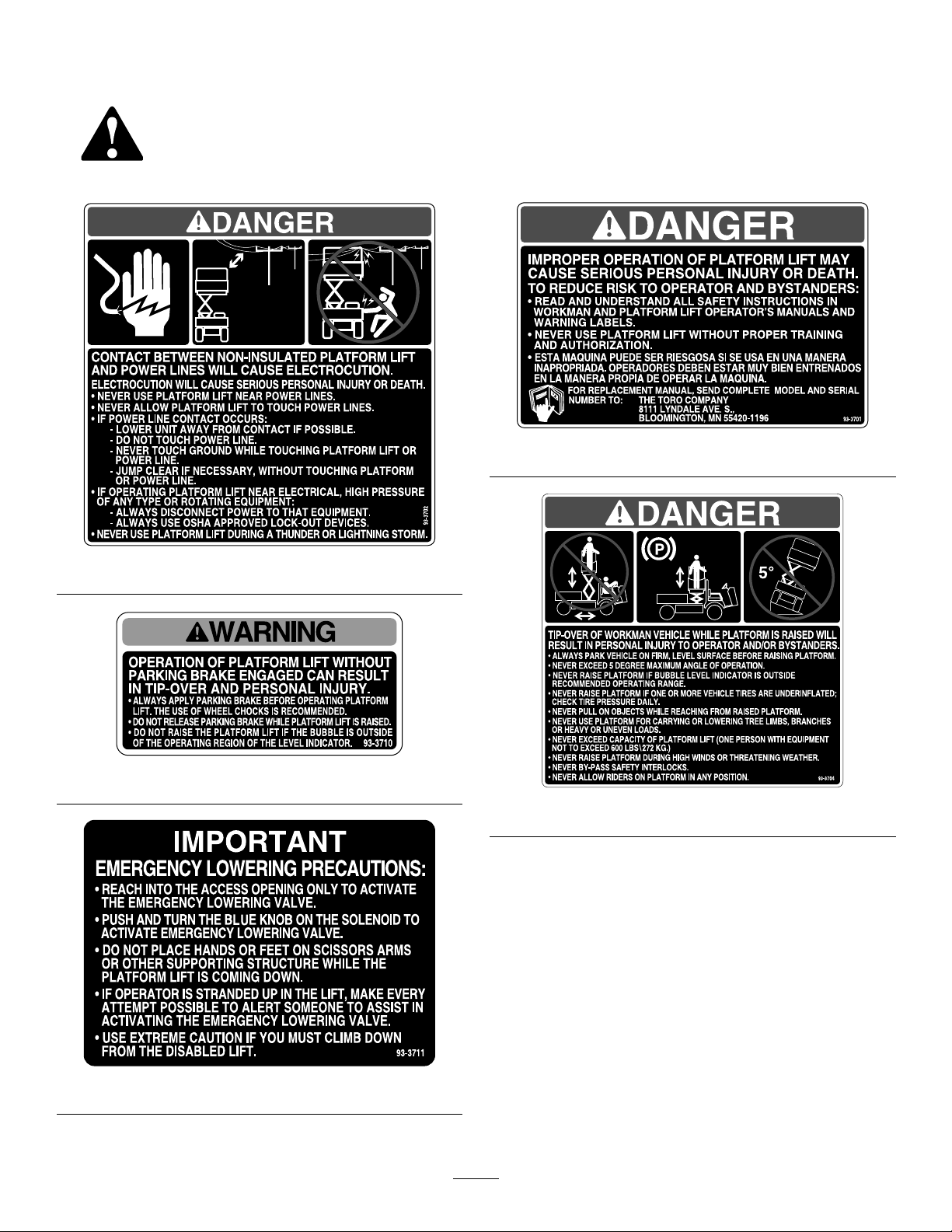
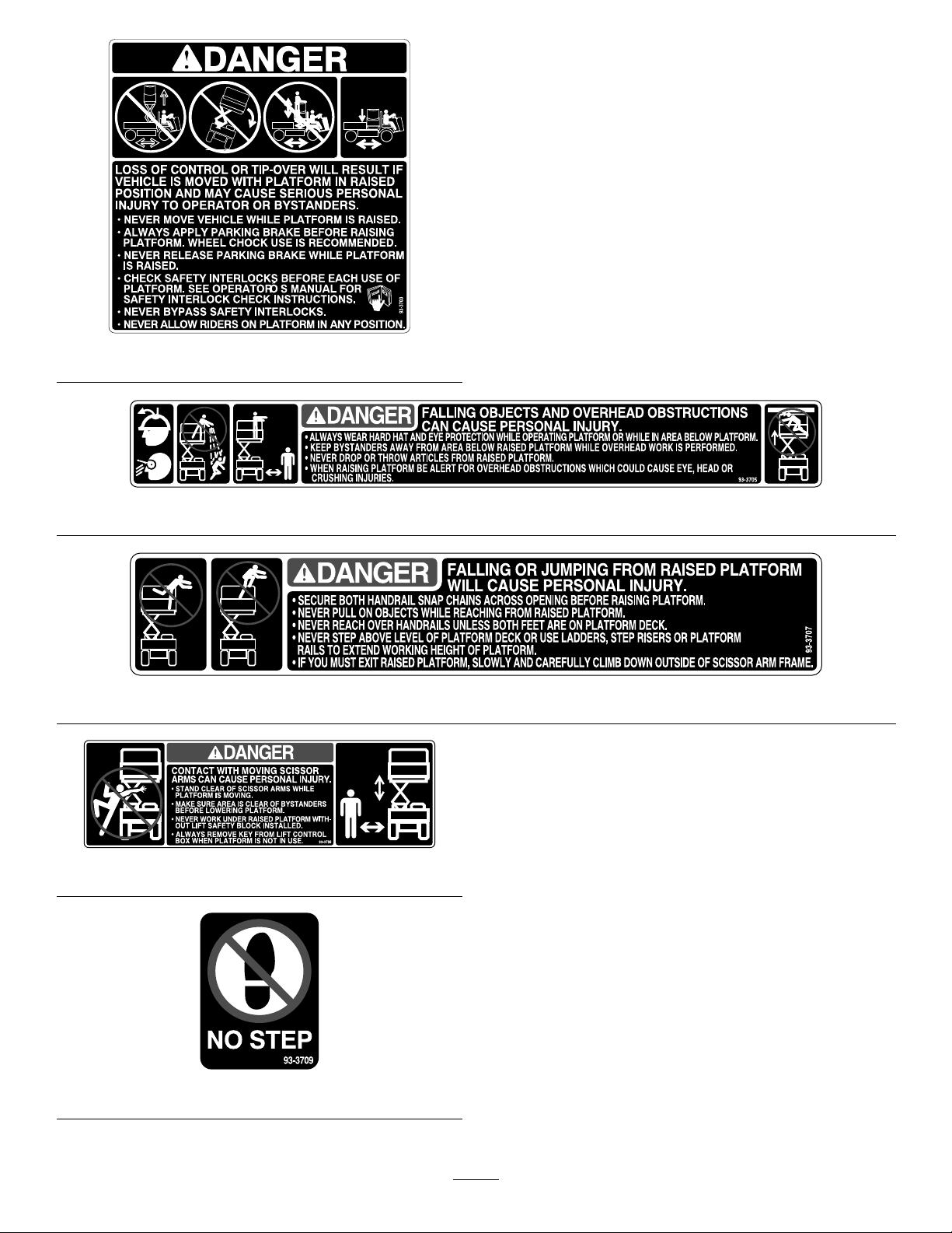
SafetyandInstructionalDecals.............................4
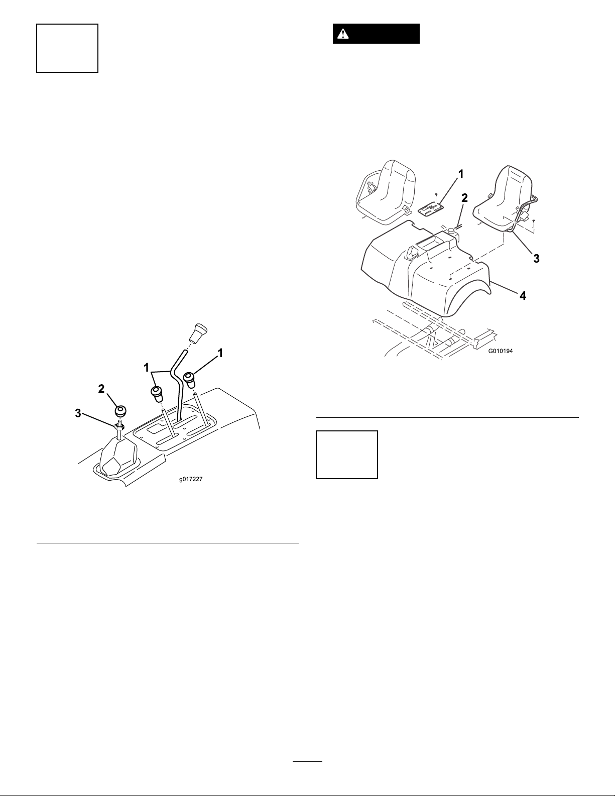
Setup...........................................................................6
1RemovetheSeat,ShroudandFender
Assemblies.......................................................7
2RemovingtheHood..........................................7
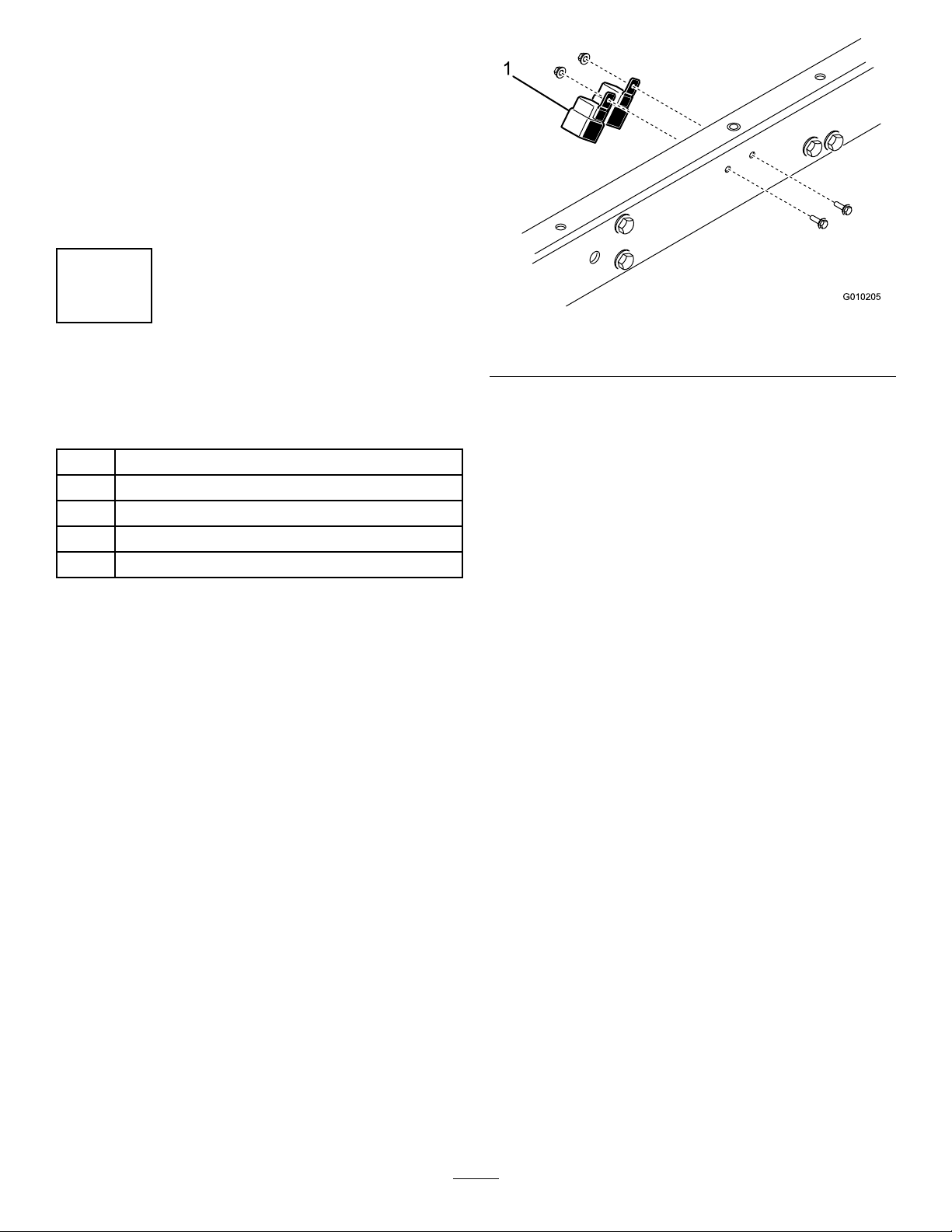
3InstalltheMainWireHarnessw/Relays..............8
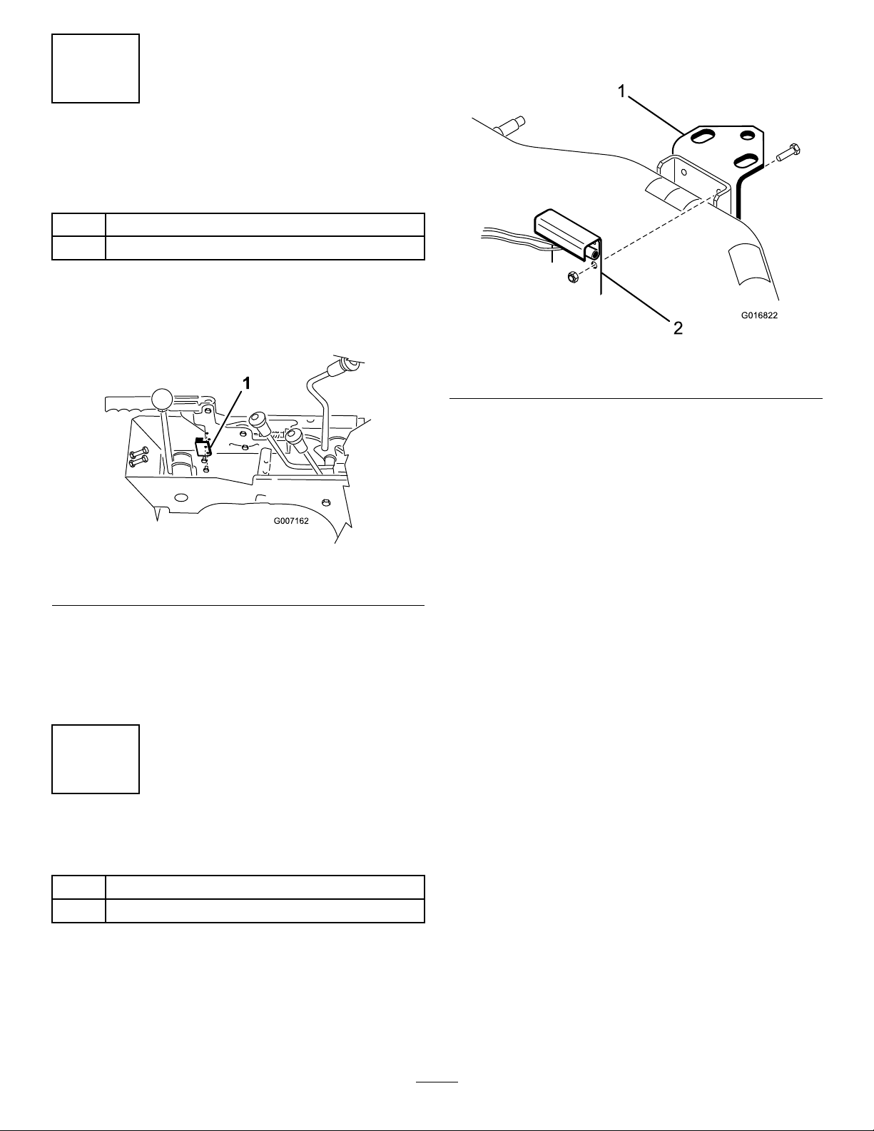
4MounttheParkingBrakeSwitch.........................8
5MountRearLevelSwitch...................................9
6ReinstallHood................................................10
7MountLiftontoVehicleFrame........................10
8ConnectWires.................................................11
9ReconnectBattery...........................................11
10MountCircularBubbleLevel..........................11
11InstallDecals.................................................12
ProductOverview......................................................13
Controls.............................................................13
Operation...................................................................14
CheckOilLevel..................................................14
CheckTirePressure............................................14
EngagingSafetyLocks........................................14
OperatingtheLift...............................................15
OperatingTips...................................................17
Maintenance...............................................................19
CheckSafetyCircuits..........................................19
BatteryCare.......................................................19
Schematics.................................................................21
©2011—TheToro®Company
8111LyndaleAvenueSouth
Bloomington,MN554202
Contactusatwww.Toro.com.
PrintedintheUSA.
AllRightsReserved

Safety
BeforeOperating
•Readandunderstandthecontentsofthismanual
beforeoperatingtheplatformlift.Becomefamiliar
withallcontrolsandknowhowtostopquickly.A
replacementmanualisavailableatwww.Toro.com.
•Donotallowchildrentooperatethelift.Donot
allowadultstooperateitwithoutproperinstruction.
•Keepallshieldsandsafetydevicesinplace.Ifa
safetydevice,shieldordecalmalfunctions,becomes
damagedorillegible,replaceitbeforeoperation
iscommenced.Toassureliftisinsafeoperating
condition,tightenloosenuts,boltsandscrews.
WhileOperating
•Donotusenearelectricalpowerlines.Neverallow
platformlifttotouchpowerlines.
•Donotuseplatformliftduringlightning,
thunderstorms,orhighwinds.
•Nevermovevehiclewhileplatformisraised.
•Alwaysapplyparkingbrakebeforeraisingplatform.
Wheelchockuseisrecommended.
•Neverreleaseparkingbrakewhileplatformisraised.
•Checksafetyinterlocksbeforeeachuseofplatform.
Seeoperator'smanualforsafetyinterlockcheck
instructions.
•Neverbypasssafetyinterlocks.
•Neverallowridersonplatforminanyposition.
•Alwaysparkvehicleonrm,levelsurfacebefore
raisingplatform.
•Neverexceed5degreemaximumangleofoperation.
•Neverraiseplatformifbubblelevelindicatoris
outsiderecommendedoperatingrange.
•Neverraiseplatformifoneormorevehicletiresare
underinated;checktirepressuredaily.
•Neverpullonobjectswhilereachingfromraised
platform.
•Neveruseplatformforcarryingorloweringtree
limbs,branchesorheavyorunevenloads.
•Neverexceedcapacityofplatformlift,oneperson
withequipmentnottoexceed600lbs.(272Kg).
•Alwayswearhardhatandeyeprotectionwhile
operatingplatformorwhileinareabelowplatform.
•Neverdroporthrowarticlesfromraisedplatform.
•Whenraisingplatformbealertforoverhead
obstructionswhichcouldcauseeye,headorcrushing
injuries.
•Standclearofscissorarmswhileplatformismoving.
•Makesureareaisclearofbystandersbeforelowering
platform.
Maintenance
•Alwaysremovekeyfromliftcontrolboxwhen
platformisnotinuse.
•Ensureliftisinsafeoperatingcondition.Keepnuts,
boltsandscrewstight.
•Neverworkunderraisedplatformwithoutliftsafety
blocksinstalled.
•Tobesureofoptimumperformanceandsafety,
alwayspurchasegenuineTororeplacementpartsand
accessories.Replacementpartsandaccessoriesmade
byothermanufacturerscouldbedangerous.Such
usecouldvoidtheproductwarrantyofTheToro®
Company.
3

SafetyandInstructionalDecals
Safetydecalsandinstructionsareeasilyvisibletotheoperatorandarelocatednearanyareaof
potentialdanger.Replaceanydecalthatisdamagedorlost.
93-3702
93-3710
93-3711
93-3701
93-3704
4

93-3703
93-3705
93-3707
93-3706
93-3709
5

Installation
LooseParts
Usethechartbelowtoverifythatallpartshavebeenshipped.
ProcedureDescriptionQty.Use
1Nopartsrequired–Removetheseat,shroudandfender
assemblies
2Nopartsrequired–Removethehood
MainWireHarnessw/Relays1
CableTie7
Screw,1/4x3/4inch2
Nut,1/4inch2
3
Fuse1
Installmainwireharnessw/relays
Parkingbrakeswitch1
4Screws2MounttheParkingBrakeSwitch
Rearlevelswitchbracket1
5Rearlevelswitchw/harness1Mountrearlevelswitch
6Nopartsrequired–Reinstallhood
ReinforcingPlate2
FlangeHD.Capscrew,3/8x1inch4
7Flangenut,3/8inch4
Mountliftontovehicleframe
8Nopartsrequired–Connectwires
9Nopartsrequired–Reconnectbattery
10CircularBubbleLevel1Mountcircularbubblelevel
OperationDecal1
11NoStepDecal2Installdecals
MediaandAdditionalParts
DescriptionQty.Use
Key1Usethekeytounlockthependantcontroltoauthorizethe
useoflift
OperatorsManual1Readbeforeoperatingthelift
PartsCatalog1Usetoreferencepartnumbers
The1/3platformliftisdesignedtobeusedonlywitha
WorkmanVehicleandmustbemountedwiththewiring
harness,level,decals,switchesandallinterlockswitches
installed.The1/3platformliftwillonlyworkon
Workman3000–4000seriesvehicleswithserialnumbers
240000001andupandallWorkmanHD,HDXand
HDX-Dvehicles.
6

1
RemovetheSeat,Shroudand
FenderAssemblies
NoPartsRequired
Procedure
1.Positionvehicleonaclean,levelsurface,stopengine,
engageparkingbrakeandremovekeyfromignition
switch.Disconnectpositivecablefrombattery.
2.Removethebedfromthevehicle,ifsoequipped.
Refertothevehicleoperator’smanualforthe
removalprocedure.
3.Unscrewandremoveallknobsfromconsolelevers
andfromthegearshiftlever(Figure2).Also,remove
thejamnutfromthegearshiftlever(Figure2).
g017227
3
Figure2
1.Consolelevers3.Jamnut
2.Gearshiftlever
4.Remove(6)screwssecuringoutsideedgeofcenter
consolecoverplatetoframeandremovecoverplate
(Figure3).
5.Disconnectthereservoirhosefromtheradiatorand
plugorclampittoretaincoolant(Figure3).Remove
theoperatorshieldfromtheROPS.
CAUTION
Pressurizedhotcoolantescapingcancause
seriousburns.
Allowenginetocoolenoughtotouchbefore
removingoverowtubeorradiatorcap.
6.Removethecapscrewssecuringtheseatsandshroud
tomountingbrackets(Figure3).Removetheseats
andshroud.
Figure3
1.Consolecoverplate3.Seat
2.Reservoirhose4.Shroud
2
RemovingtheHood
NoPartsRequired
ForWorkman3000–4000series
vehicleswithserialnumbers240000001
andup
1.Removethe(6)screwsandnutssecuringthebumper
tothevehicleframeandremovethebumper.
2.Removethe(7)screwssecuringthefronthoodto
thevehicleframeandremovethehood.
ForWorkmanHD,HDXandHDX-D
vehicles
1.Positionthevehicleonalevelsurface,stopthe
engine,engagetheparkingbrakeandremovethekey
fromtheignition.
7

2.Whilegraspingthehoodintheheadlightopenings,
liftuponthehoodtoreleasethelowermounting
tabsfromthebumperslots.
3.Pivotthebottomofthehoodupwarduntilthetop
mountingtabscanbepulledfromthedashslots.
4.Pivotthetopofthehoodforwardandunplugthe
wireconnectorsfromtheheadlights.
5.Removethehood.
3
InstalltheMainWireHarness
w/Relays
Partsneededforthisprocedure:
1MainWireHarnessw/Relays
7CableTie
2Screw,1/4x3/4inch
2Nut,1/4inch
1Fuse
ForWorkman3000–4000series
vehicleswithserialnumbers240000001
andup
1.Insertendofwireharness,withmaleandfemale
spadeterminalsonit,upthroughopeninginvehicle
oorboard,towarddashpanel,followingvehicle
wireharness.Secureharnesstovehiclewireharness
with(2)cableties.
2.Locatered/blackwireconnectedto"I"terminalof
ignitionswitch.Removewirefrom“I”terminaland
plugintoappropriatewireharnessterminal.Plug
remainingharnessterminalontoignitionswitch“I”
terminal.
3.Removefastenerssecuringwireharnesscoverto
undersideofvehicleoorandremovecover.
4.Routewireharnessrearwardtoconsolearea.
Harnessmustnotinterferewithanyhot(exhaust)or
movingparts.Securetheharnesswithcableties.
5.Mounttherelaystotheleftframechannelwith2(1/4
x3/4inch)screwsand(1/4inch)nuts(Figure4).
Note:Ifthevehicleisequippedwithhighow
hydraulics,locateanothersuitablemountinglocation.
Figure4
1.Relays
ForWorkmanHD,HDXandHDX-D
vehicles
1.Insertendofwireharness,withmaleandfemale
spadeterminalsonit,upthroughopeninginvehicle
oorboard.
2.Locateanemptyslotinthefuseblock.Ifnoempty
slotisavailable,anadditionalfuseblock(Toropart
no.92–2641)willhavetobeadded.
3.Inserttheincludedfuseintotheemptyfuseblock
slotandconnectthewireharnessspadeterminalto
thecorrespondingspadeterminalonthefuseblock.
4.Removefastenerssecuringwireharnesscoverto
undersideofvehicleoorandremovecover.
5.Routewireharnessrearwardtoconsolearea.
Harnessmustnotinterferewithanyhot(exhaust)or
movingparts.Securetheharnesswithcableties.
6.Mounttherelaystotheleftframechannelwith2(1/4
x3/4inch)screwsand(1/4inch)nuts(Figure4).
Note:Ifthevehicleisequippedwithhighow
hydraulics,locateanothersuitablemountinglocation.
8

4
MounttheParkingBrake
Switch
Partsneededforthisprocedure:
1Parkingbrakeswitch
2Screws
Procedure
1.Mounttheparkingbrakeswitchtotheparkingbrake
mountwithtwoscrewsasshowninFigure5.
Figure5
1.Switch
2.Plugswitchwireconnectorintoliftwireconnector
harness.
3.Removetheloopbackconnectorfromthevehicle
wireharnesslabeled1/3lift.Connecttheliftwire
harnesstothevehiclewireharness.
5
MountRearLevelSwitch
Partsneededforthisprocedure:
1Rearlevelswitchbracket
1Rearlevelswitchw/harness
ForWorkman3000–4000series
vehicleswithserialnumbers240000001
andup
1.Removethelocknutssecuringthetopofthehitch
platetorearaxle(Figure6).Usingtheuppersetof
mountingholes,mountthelevelswitchbracketto
rearaxlewiththelocknutspreviouslyremoved.
G016822
Figure6
1.Hitchplate2.Levelswitchbracket
2.Routeswitchharnessforward,alongdifferential
lockcabletoleftsideofmachine.Harnessmustnot
interferewithanyhot(exhaust)ormovingparts.
Secureharnesstodifferentiallockcablewithcable
ties.
ForWorkmanHD,HDXandHDX-D
vehicles
1.Removethecapscrewssecuringthehitchplatetothe
rearaxle(Figure7).Usingthelowersetofmounting
holes,looselymount2washersandlevelswitch
brackettorearaxlewiththecapscrewspreviously
removed.Thewashersaretobepositionedbetween
thehitchplateandaxle.Tightenallfourcapscrews.
9

G016821
Figure7
1.Hitchplate2.Levelswitchbracket
2.Routeswitchharnessforward,alongshiftcableto
leftsideofmachine.Harnessmustnotinterferewith
anyhot(exhaust)ormovingparts.Secureharnessto
shiftcablewithcableties.
6
ReinstallHood
NoPartsRequired
Procedure
1.Reinstallhoodtoframe.
2.ReinstallROPSshieldshroud,seats,seatframeand
consolecoverplate,ifapplicable.
3.Reinstalloverowtubetoradiator.Checkcoolant
levelandreplenish,ifrequired.
7
MountLiftontoVehicleFrame
Partsneededforthisprocedure:
2ReinforcingPlate
4FlangeHD.Capscrew,3/8x1inch
4Flangenut,3/8inch
1.Removeanyaccessoriesmountedtotopofframein
forwardpositionsuchasa1/3bed,powerplatform,
H.D.HitchFrameextensiontubes(Figure8),etc.
Figure8
1.Hitchframeextensiontube
2.Locateandremovethethreadedinsertfromthe
mountingholeinleftandrightvehicleframe
channels,asshowninFigure9.
Figure9
1.Vehicleframechannel2.Threadedinsert
Note:Topreventliftscissorarmsfromexpanding,
pickuptheplatformliftfromthebottomwhen
positioningonframe.
3.Positionliftontoframealigningmountingholeswith
holesinframe(Figure10).
10

Figure10
1.Lift2.Reinforcingplate
4.Mounteachsideoflifttoframechannelswith
areinforcingplateand(2)3/8-16x1inchlarge
angeheadcapscrewsandangenuts(Figure10).
Reinforcingplatestobeusedinrearmountingholes
only.
Note:OnHD,HDXandHDX-Dmodels,theframe
isequippedwithweldnutssotheangenutsarenot
requiredtosecurethefrontofthelifttotheframe
channels.
8
ConnectWires
NoPartsRequired
Procedure
1.Plugtheconnectorsfromthefrontandrearharness’
intotheliftharness.
2.Locatetheoilpressureswitchontheengineand
unplugthewireconnectedtotheswitch.
3.Routethegreenwirefromthefrontharnessand
connectittotheoilpressureswitch.
4.Plugthewirepreviouslyremovedfromtheoil
pressureswitchintotheharnesspiggyback
connector.
5.Connectgroundwirefromlifttoengineground.
6.Removethenutfromthepositivebatteryclamp
(Figure11).
7.Insertthepositivewirefromtheliftandthering
terminalendoftheredwirefromthefrontharness
ontothecableclampscrewandlooselysecureitwith
thenutremoved(Figure11).
1
2
3
g017228
Figure11
1.Positiveliftwire3.Redwirefromfront
harness
2.Positivebatterycable
clamp
8.Makesurewiringisclearofallhotorrotatingparts.
Securewithcabletiesasrequired.
9
ReconnectBattery
NoPartsRequired
Procedure
1.Reinstallpositivebatterycabletobattery.
2.Sliderubberbootoverpositiveterminaltoprevent
possibleshort-outfromoccurring.
11

10
MountCircularBubbleLevel
Partsneededforthisprocedure:
1CircularBubbleLevel
Procedure
Afxcircularleveltotopofconsolecoverpositioningas
showninFigure12.
G01681 1
Figure12
1.Circularlevel2.Operationdecal
11
InstallDecals
Partsneededforthisprocedure:
1OperationDecal
2NoStepDecal
ForWorkman3000–4000series
vehicleswithserialnumbers240000001
andup
1.Afxoperationdecaltotopofconsolecover
positioningasshowninFigure12.
2.Afxa"NoStep"decaltotopofeachfueltank
mountingstrap,asshowninFigure13.
Figure13
1.No—Stepdecal
ForWorkmanHDXandHDX-Dvehicles
1.Afxoperationdecaltotopofconsolecover
positioningasshowninFigure12.
2.Afxthe"NoStep"decalstotopofradiator,as
showninFigure14.
G01021 1
1
Figure14
1.No—Stepdecal
12

ProductOverview
Controls
UpButton
Press"UP"buttontoraiselift(Figure15).
DownButton
Press"DOWN"buttontolowerlift(Figure15).
KeySwitch
Rotatekeyswitchtoauthorizeuseoflift.Removekey
fromliftpendantcontrolswitchtopreventoperation
whenunattended.(Figure15).
1
2
3
4
G016810
Figure15
1.Pendantcontrol3.DOWNbutton
2.UPbutton4.Keyswitch
EmergencyLoweringValveKnob
Pushtheblueknobinward,rotateit90degrees
counterclockwise,andpullitouttoactivatethe
emergencyloweringvalve(Figure16).Tostopthelift
andreturnittonormaloperation,pushtheblueknob
inward,rotateit90degreesclockwiseandpullitout.
1
G016809
Figure16
1.Emergencyloweringvalveknob(blueknob)
13

Operation
CheckOilLevel
Theliftreservoirislledatthefactorywith5W30oil.
Checklevelbeforeliftisrstoperatedandevery8
hoursordaily,thereafter.Capacityofsystemis1.5qt.
1.Positionthevehicleonalevelsurface.
2.Raiseliftandengagethesafetylocks.Refertothe
EngagingSafetyLockssectionandtheOperation
chapter.
Note:Ifliftcannotberaisedduetothelackofoil
inthereservoir,itmayberaisedwithahoistand
safetylocksengaged,toexposereservoirbreather
cap.
3.Theoillevelcanbeviewedthroughthereservoir.If
theoillevelislow,proceedtonextstep.
4.Cleanareaaroundreservoirbreathercap(Figure17).
1
G016812
Figure17
1.Reservoircap
5.Unscrewbreathercapfromtopofreservoir.
6.Fluidshouldbewithin2inchesfromtopof
reservoir.Iflevelislow,addenough5W30oilto
achievetheproperlevel.DONOTOVERFILL.
CheckTirePressure
Checktirepressureevery8hoursordailytoassure
properlevels.
Refertothevehicleoperator'smanualforpropertire
inationspecication.
EngagingSafetyLocks
1.Positionthevehicleonalevelsurface.
2.Setparkingbrakeandchockwheels.
3.Rotatevehiclekeyswitchto"Off"position.
4.Whilestandingnexttomachine,grasppendant
controlandrotateliftkeyswitchto"On"position.
Checkoverheadclearanceandforanyobstructions.
5.Press"UP"buttontoraiselifthighenoughto
engagesafetylocks.Standclearofscissorarms
whileplatformismoving.
DANGER
Contactwithmovingscissorarmscancause
personalinjury.
•Standclearofscissorarmswhileplatform
ismoving.
•Makesureareaisclearofbystandersbefore
loweringplatform.
•Neverworkunderraisedplatformwithout
liftsafetylocksengaged.
•Alwaysremovekeyfromliftcontrolbox
whenplatformisnotinuse.
6.Rotateboththesafetylocks,fromtheirstorage
positions,untiltheyrestinsidethebaseframe,thus
inthepathofthescissorsrollers(Figure18).
14

1
2
G016813
Figure18
1.Safetylock(2)2.Scissorsroller(2)
DANGER
Platformliftcancrushandcausepersonal
injury.
•Neverworkunderraisedplatformwithout
liftsafetylocksengaged.
•Neverusesafetyblockstosupportaload
onlift.
7.Press"DOWN"buttononpendantcontroland
lowerliftuntilrollersgentlycontactsafetylocks.
Oncethelocksarefullyengagedwiththescissors
rollers,continuetoholdthe“DOWN”buttonfor
5-10secondstorelievethepressurewithinthe
hydrauliccircuit
8.Toremovesafetylocks:
•Raiseliftslightly.
•Returnsafetylockstostorageposition.
OperatingtheLift
The1/3platformliftisdesignedtobeusedonlywith
aWorkmanVehicleandmustbemountedwiththe
wiringharness,level,decals,switchesandallinterlock
switchesinstalled.
DANGER
Improperoperationofplatformliftmaycause
seriouspersonalinjuryordeath.Toreduceriskto
operatorandbystanders:
•Readandunderstandallsafetyinstructions
inWorkmanandPlatformLiftOperator's
Manualsandwarninglabels.
•Neveruseaplatformliftwithoutpropertraining
andauthorization.
Theelectricalcontrolsystemoftheliftrequiresthe
vehicletobeparkedonaslopeoflessthana5degree
angle,parkingbrakeengagedandthevehiclekeyinthe
“ON”positionwiththeengineoffinordertoactivate
theliftcircuit.
Operating
1.Setparkingbrakeandchockwheels.
2.Rotatevehiclekeyswitchto"ON"positionwith
theengine“OFF”.
3.Climbintoplatformandsecuresafetychainsacross
entry.
4.Grasppendantcontrolandrotateliftkeyswitchto
"On"position.
5.Press"UP"buttontoraiselift;"DOWN"button
tolowerlift(Figure19).
Note:Iftheoilinthevehicleengineiscold,itmay
takeseveralsecondsfortheengineoilpressureto
bleeddownaftertheengineisturnedoff.Thelift
willnotoperateuntiltheoilpressureindicatorlight
ison.
WARNING
Operationofplatformliftwithoutparkingbrake
engagedcanresultintip-overandpersonal
injury.
•Alwaysapplyparkingbrakebeforeoperating
platformlift.Theuseofwheelchocksis
recommended.
•Donotreleaseparkingbrakewhileplatform
liftisraised.
•Donotraisetheplatformliftifthebubbleis
outsideoftheoperatingregiononthelevel
indicator.
15

1
2
3
4
G016810
Figure19
1.Pendantcontrol3.Downbutton
2.UPbutton4.Keyswitch
DANGER
Lossofcontrolortip-overwillresultifvehicle
ismovedwithplatforminraisedpositionand
maycauseseriouspersonalinjurytooperator
orbystanders.
•Nevermovevehiclewhileplatformisraised.
•Alwaysapplyparkingbrakebeforeraising
platform.Wheelchockuseisrecommended.
•Neverreleaseparkingbrakewhileplatform
israised.
•Checksafetyinterlocksbeforeeachuseof
platform.Seeoperator'smanualforsafety
interlockcheckinstructions.
•Neverbypasssafetyinterlocks.
•Neverallowridersonplatforminany
position.
Ifliftdoesnotoperate:
•Makesurevehiclekeyandliftkeyarein"ON"
position.
•Makesurevehicleisparkedonlessthana5
degreeangleslope.
•Makesurevehicleparkingbrakeis"On".
•Makesurevehicleengineis“OFF”andtheoil
pressurelightis“ON”
6.Whennishedwithworkoperation,lowerliftallthe
waydowntostopsandremovekeyfromliftpendant
controltopreventoperationwhenunattended.
Important:Ifenginekillswhenreleasing
parkingbrake,itmayindicatethatliftisnot
completelylowered.Vehiclecannotbedriven
withliftraisedatanyheight.
DANGER
Contactbetweennon-insulatedplatformlift
andpowerlineswillcauseelectrocution.
•Electrocutionwillcauseseriouspersonal
injuryordeath.
•Neveruseplatformliftnearpowerlines.
•Neverallowplatformlifttotouchpower
lines.
•Ifpowerlinecontactoccurs:
–Lowerunitawayfromcontactifpossible.
–Donottouchpowerline.
–Nevertouchgroundwhiletouching
platformliftorpowerline.
–Jumpclearifnecessary,withouttouching
platformliftorpowerline.
•Ifoperatingplatformliftnearelectrical,high
pressureoranytypeofrotatingequipment:
–Alwaysdisconnectpowertothat
equipment.
–AlwaysuseOSHAapprovedlock-out
devices.
•Neverusetheplatformliftduringathunder
orlightningstorm.
Lowertheplatformliftandavoidopenareas
intheeventofthreateningweather.
EmergencyLowering
1.Pushtheblueknobinward,rotateit90degrees
counterclockwise,andpullitouttoactivatethe
emergencyloweringvalve(Figure20).
16

DANGER
Contactwithmovingscissorarmscancause
personalinjury.
•Standclearofscissorarmswhileplatform
ismoving.
•Makesureareaisclearofbystandersbefore
loweringplatform.
•Neverworkunderraisedplatformwithout
liftsafetyblocksinstalled.
•Alwaysremovekeyfromliftcontrolbox
whenplatformisnotinuse.
1
G016809
Figure20
1.Emergencyloweringvalveknob(blueknob)
2.Tostoptheliftandreturnittonormaloperation,
pushtheblueknobinward,rotateit90degrees
clockwiseandpullitout(Figure20).
DANGER
Fallingorjumpingfromraisedplatformwill
causepersonalinjury.
•Securebothhandrailsnapchainsacross
openingbeforeraisingplatform.
•Neverpullonobjectswhilereachingfrom
raisedplatform.
•Neverreachoverhandrailsunlessbothfeet
areonplatformdeck.
•Neverstepabovelevelofplatformdeckor
useladders,steprisersorplatformrailsto
extendworkingheightofplatform.
•Ifyoumustexitraisedplatform,slowlyand
carefullyclimbdownoutsideofscissorarm
frame.
OperatingTips
Theelectricalsystem,batteryandhydraulicliftcylinder
arenotdesignedforcontinuoususe.Allowsome
time,approximately1-1/2to2minutes,betweenlift
operationstomaintainoperatingtemperatures.
Frequentusewithouttheenginerunningoridling,
betweenliftuse,maydischargethebattery.Ifengine
operationisnotpossibletokeepbatterycharged,it
maybenecessarytosupplementoperationwithanover
nightbatterycharger.
Checkthespecicgravityoftheuidinthebatteryto
assureitisfullycharged.RefertoBatteryCaresection.
DANGER
Tip-overofWorkmanVehiclewhileplatformis
raisedwillresultinpersonalinjurytooperator
and/orbystanders.
•Alwaysparkvehicleonrm,levelsurfacebefore
raisingplatform.
•Neverexceed5degreemaximumangleof
operation.
•Neverraiseplatformifbubblelevelindicatoris
outsiderecommendedoperatingrange.
•Neverraiseplatformifoneormorevehicletires
underinated;checktirepressuredaily.
•Neverpullonobjectswhilereachingfrom
raisedplatform.
•Neveruseplatformforcarryingorlowering
treelimbs,branchesorheavyorunevenloads.
•Neverexceedcapacityofplatformlift(one
personwithequipmentnottoexceed600lbs.)
•Neverraiseplatformduringhighwindsor
threateningweather.
•Neverby-passsafetyinterlocks.
•Neverallowridersonplatforminanyposition.
Note:Toprailofplatformliftishigherthanvehicle
ROPSsobealerttolowoverheadareaswhen
transporting(driving)vehicle.
17

DANGER
Fallingobjectsandoverheadobstructionscan
causepersonalinjury.
•Alwayswearhardhatandeyeprotectionwhile
operatingplatformorwhileinareabelow
platform.
•Neverdroporthrowarticlesfromraised
platform.
•Whenraisingplatformbealertforoverhead
obstructionswhichcouldcauseeye,heador
crushinginjuries.
18

Maintenance
CheckSafetyCircuits
Theelectricalsafetycircuitsoftheliftrequirethevehicle
tobeparkedonaslopeoflessthan5degrees,parking
braketobeengagedandtheignitionkeyoffinorder
toactivatetheliftcircuit.
Toverifyparkingbrakeswitch
operation:
1.Positionthevehicleonalevelsurface,setparking
brakeandchockwheels.
2.Withtheengine“OFF”,rotatethevehiclekey
switchtothe"ON"position.Whilestandingnextto
machine,grasppendantcontrolandrotateliftkey
switchto"On"position.Press"UP"buttonand
raiseliftafewinches.Releasebutton.
3.Releaseparkingbrakeandtrytoraiseliftagain.Lift
mustnotrise.Ifliftdoesnotraise,safetycircuitis
operatingcorrectlyandproceedtonextstep.Iflift
risesthereisamalfunctionintheelectricalcircuit
thatmustberepairedbeforeoperatinglift.
4.Withtheplatformpartiallyraisedandparkingbrake
released,trytostartengine.Ifenginedoesnot
startandremainrunning,safetycircuitisoperating
correctly.Lowerliftallthewayandproceedtonext
step.Ifenginestartsandremainsrunningthereis
amalfunctionintheelectricalcircuitthatmustbe
repairedbeforeoperatinglift.
Toverifyrearaxlelevelswitch
operation:
1.Positiononesideofvehicle(rearaxle)onaslope
greaterthan5degrees(oorjack,moundofmaterial
orsmallhill).
2.Setparkingbrakeandchockwheels.
3.Withtheengine“OFF”,rotatethevehiclekey
switchtothe"ON"position.Whilestandingnextto
machine,grasppendantcontrolandrotateliftkey
switchto"On"position.Press"UP"buttonand
trytoraiselift.Ifliftdoesnotraise,safetycircuitis
operatingcorrectly.Raiseoppositesideofmachine
andrepeatprocedure.Ifliftrises,witheithersideof
machineinraisedposition,thereisamalfunction
intheelectricalcircuitthatmustberepairedbefore
operatinglift.Lowerliftimmediately.
BatteryCare
1.Batteryelectrolytelevelmustbeproperlymaintained
andthetopofthebatterykeptclean.Ifthemachine
isstoredinalocationwheretemperaturesare
extremelyhigh,thebatterywillrundownmore
rapidlythanifthemachineisstoredinalocation
wheretemperaturesarecool.
2.Keeptopofbatterycleanbywashingperiodically
withabrushdippedinammoniaorbicarbonateof
sodasolution.Flushthetopsurfacewithwaterafter
cleaning.Donotremovethellcapwhilecleaning.
3.Batterycablesmustbetightonterminalstoprovide
goodelectricalcontact.
4.Ifcorrosionoccursatterminals,removebattery
cover,disconnectcables,negative(-)cablerstand
scrapeclampsandterminalsseparately.Reconnect
cables,positive(+)cablerstandcoatterminalswith
petroleumjelly.
5.Checktheelectrolytelevelevery50operatinghours
or,ifmachineisinstorage,every30days.
6.Maintaincelllevelwithdistilledordemineralized
water.Donotllcellsabovethebottomofthell
ringinsideeachcell.
7.Ifthemachinewillbestoredformorethan30
days,removethebatteryandchargeitfully.Either
storeitontheshelforonthemachine.Leavethe
cablesdisconnectedifstoredonthemachine.Store
thebatteryinacoolatmospheretoavoidquick
deteriorationofthechargeinthebattery.Toprevent
batteryfromfreezing,makesureitisfullycharged.
Thespecicgravityofafullychargedbatteryis
1.250.
DANGER
Batteryelectrolytecontainssulfuricacidwhichisa
deadlypoisonanditcausessevereburns.
•Ifyoucarelesslydrinkelectrolyteyoucoulddie
orifitgetsontoyourskinyouwillbeburned.
•Donotdrinkelectrolyteandavoidcontactwith
skin,eyesorclothing.
•Wearsafetyglassestoshieldyoureyesand
rubberglovestoprotectyourhands.
•Fillthebatterywherecleanwaterisalways
availableforushingtheskin.
•Followallinstructionsandcomplywithallsafety
messagesontheelectrolytecontainer.
19

WARNING
CALIFORNIA
Proposition65Warning
Batteryposts,terminals,andrelated
accessoriescontainleadandleadcompounds,
chemicalsknowntotheStateofCalifornia
tocausecancerandreproductiveharm.
Washhandsafterhandling.
WARNING
Chargingthebatteryproducesgassesthatcan
explode.
Neversmokenearthebatteryandkeepsparksand
amesawayfrombattery.
WARNING
Batteryterminalsormetaltoolscouldshortagainst
metalcomponentscausingsparks.Sparkscan
causethebatterygassestoexplode,resultingin
personalinjury.
•Whenremovingorinstallingthebattery,donot
allowthebatteryterminalstotouchanymetal
partsofthemachine.
•Donotallowmetaltoolstoshortbetween
thebatteryterminalsandmetalpartsofthe
machine.
WARNING
Incorrectbatterycableroutingcoulddamagethe
machineandcablescausingsparks.Sparkscan
causethebatterygassestoexplode,resultingin
personalinjury.
•Alwaysdisconnectthenegative(black)battery
cablebeforedisconnectingthepositive(red)
cable.
•Alwaysconnectthepositive(red)batterycable
beforeconnectingthenegative(black)cable.
20
Other manuals for Workman 07347
1
Table of contents
Other Toro Utility Vehicle manuals

Toro
Toro Dingo TX 525 Manual

Toro
Toro Groundsmaster 7200 Series User manual

Toro
Toro 7205 User manual

Toro
Toro 7359 User manual

Toro
Toro Workman GTX User manual

Toro
Toro 07324 User manual

Toro
Toro Workman MDX-D User manual

Toro
Toro Workman HD 07369 User manual

Toro
Toro 07211TC User manual

Toro
Toro 07352 User manual

Toro
Toro 09833 User manual

Toro
Toro Groundsmaster 7210 User manual

Toro
Toro Workman 07170 User manual

Toro
Toro 07297 User manual

Toro
Toro 07390H Workman HDX-Auto User manual

Toro
Toro 7280 User manual

Toro
Toro 07277 Workman 2110 User manual

Toro
Toro Workman 137-2883 User manual

Toro
Toro MH-400 User manual

Toro
Toro Workman UTX User manual