Montageanleitung
Seite 3/4
WALCO V 60
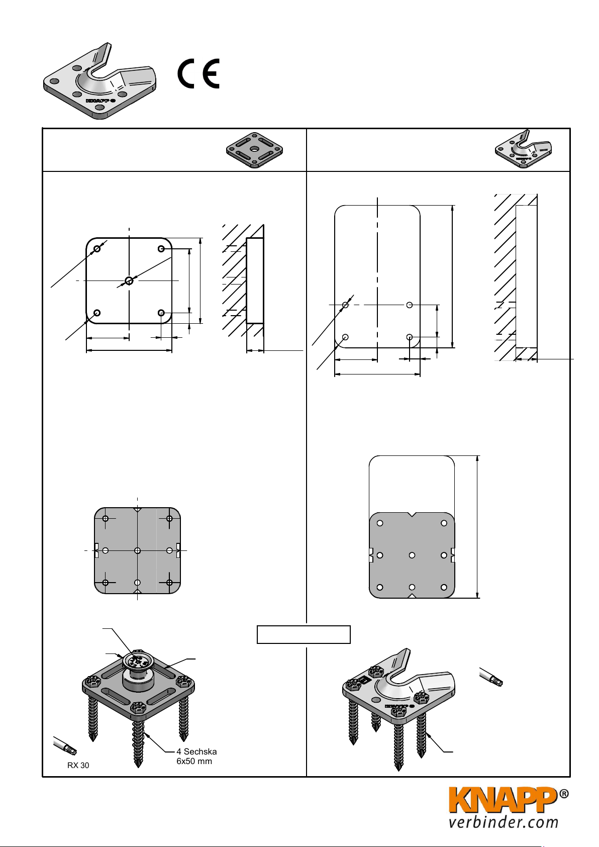
TORX 30
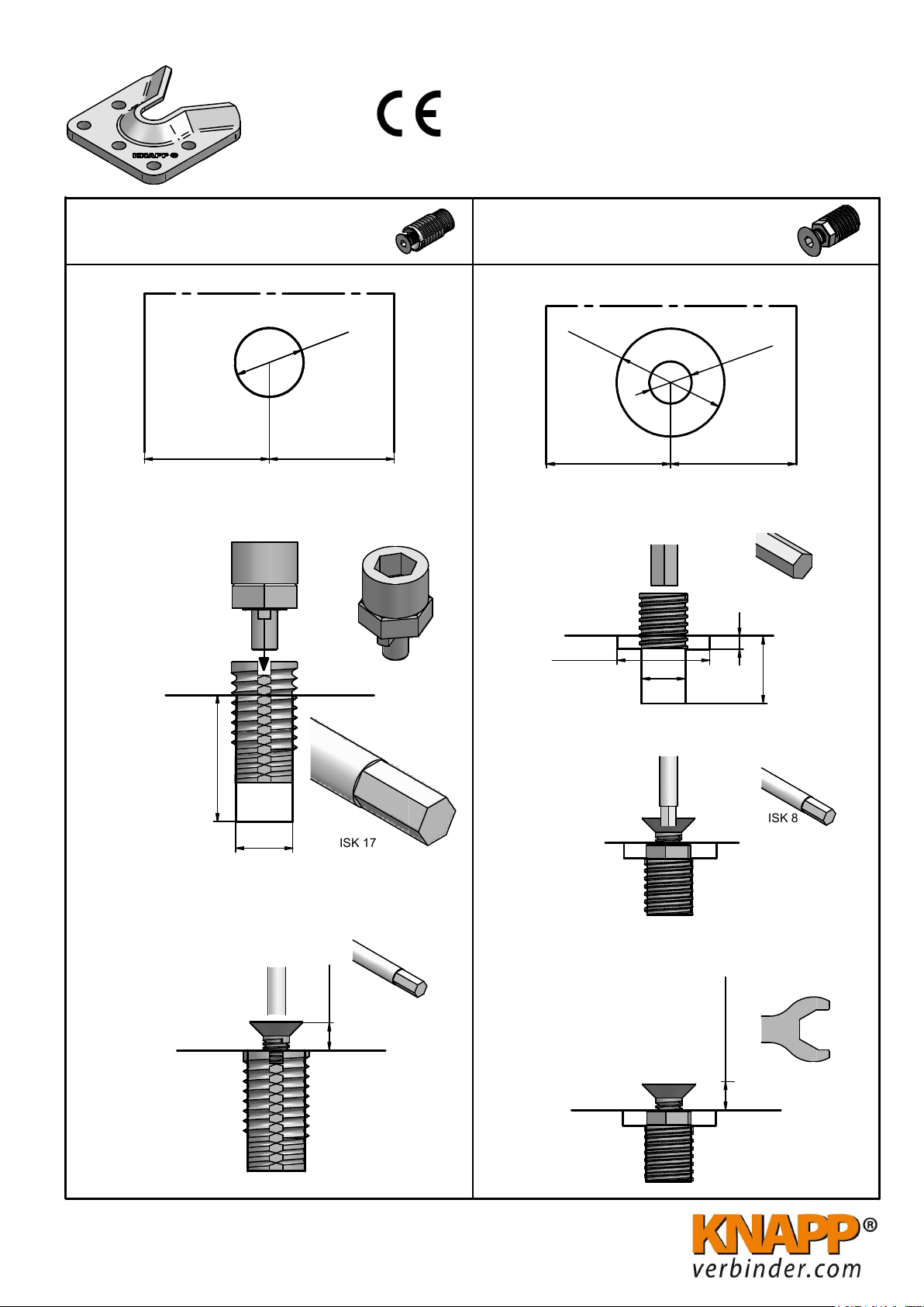
Verschraubter Kragenbolzen
Art. - Nr. K108
TORX 40
Hinweis:
Die Vollgewindeschraube kann auch mit einem Æ 5 mm
Bohrer vorgebohrt werden!
Wenn der Verbinder in der Beplankungsebene montiert
wird, kann durch Verwendung einer zusätzlichen DIN 125
M12 Unterlegscheibe an eine 15mm Beplankung angepasst
werden.
Frästiefe:
13 mm für fugenlose stramme Montage
11 mm für leichtes Einhängen (mit 2 mm Fuge)
Wandverbinder
1. Bohren
2. Eindrehen der Schraube in den Kragenbolzen
Positionierbohrung
Tiefe 50 mm
3. Verbinder montieren
1. Ausfräsung herstellen
3 Sechskant-
schrauben 6x50 mm
2. Verbinderposition mit Anreißschablone anreißen
O
5
40 40
Diese Zeichnung ist Eigentum der Knapp GmbH
WALCO® V 60 VK D12
SK 8x80
1169
VK D12
60
7,5
A
A
10060100
A-A
R7,5
7,5
Frästiefe
Art. - Nr. K578
© Knapp GmbH. Alle Maße in mm - Irrtümer, Druckfehler und Änderungen vorbehalten / all measures in mm - Errors excepted. VERSION 25. 03. 2021
Ø 4 Tiefe 50mm
alternativ Ø 5 Tiefe 10mm
Mindest- Ausfräsmaße (Alternativ kann der Verbinder auch in der
Beplankungsebene 13mm oder 15mm untergebracht werden.)