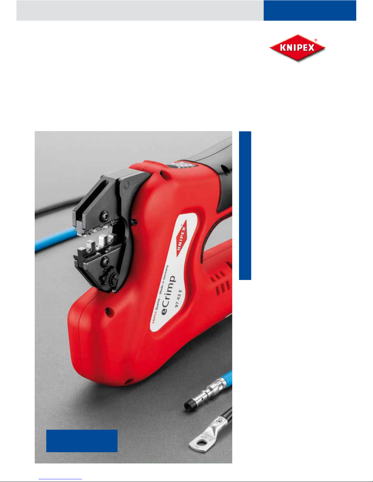
KNIPEX eCrimp 97 43 E User manual

Manual eCrimp (97 43 E)
Table of Contents
1. Intended use 2
2. General safety instructions 2
3. Terminology used 3
4. Symbols used on the equipment
and rating plate details
3
5. Scope of delivery 4
6. Technical specications 4
7. Brief description of the crimping
tool
5
8. First use and operation 7
9. Cleaning, maintenance and repair 10
10. Disposal 12
11. Warranty 12
12. EC Declaration of Conformity 12
KNIPEX-Werk
C. Gustav Putsch KG
Oberkamper Strasse 13
42349 Wuppertal
GERMANY
Tel.: +49 (0) 202 – 47 94-0
Fax: +49 (0) 202 – 47 74 94
www.knipex.de
Read these
Operating Instructions
before starting work!
Rev.: 2013-08-29

2
Rev.: 2013-08-29
Manual eCrimp (97 43 E)
1. Intended use
The crimping tools are designed exclusively for use with die sets that
are either distributed by KNIPEX or which KNIPEX has declared as being
compatible. The tools and the die sets must be used solely for the purpose
as envisaged by KNIPEX. The tool is not intended for use in different or
more specialised applications. Any work performed with this tool that is
not in line with its intended use can cause damage to the crimping tool, its
accessories and the crimped contacts.
KNIPEX accepts no liability for losses resulting from
the use of unsuitable crimping die sets or crimping die sets from other
manufacturers; or
the use of the tool in applications that are outside the scope of the
tool’s intended use.
Using the tool “as intended” also implies following the Operating
Manual, performing inspections and maintenance work as instructed and
compliance with all applicable safety provisions in their latest published
version.
Read this Operating Manual carefully!
Follow all safety instructions as provided!
Ensure compliance with national safety standards!
Read and follow all safety instructions and guidelines! Any failure to
follow the safety instructions and guidelines as given can cause electrical
shock, re and/or serious injury. Accordingly: Ensure that you retain all
safety instructions and guidelines for future use and always include these
when passing the equipment on to others.
2. General safety instructions
Icons are used to mark sections of text as described below. Ensure you
follow these instructions and take especial care in such situations. Also
provide other users and technicians with a full set of health and safety
instructions!
Danger of injury from airborne fragments.
If the tool is used incorrectly, or if worn or damaged
die sets and crimping tools are used, the operator risks
injury from airborne fragments.
Accordingly:
Crimping tools must be used solely by qualied personnel.
Maintenance must be performed at the required intervals.
Before each use, inspect the crimping tools and die sets for
cracks and other signs of wear.
Crimping tools and die sets with material aws or other signs
of wear must be taken out of service immediately and no
longer used.
Only use crimping tools and die sets if they are in perfect
working order.
If crimping tools or die sets have been used incorrectly, they
must be removed from service and inspected by an authorised
service centre.
Damage to/malfunctioning of the crimping tool and die
set as a result of improper handling.
Accordingly:
Do not continue to use worn crimping tools – replace
them immediately.
For transportation and storage, use the carrying case
and store the crimping tools and die sets in a dry
place.
Ensure all damage is inspected without delay by an
authorised service centre.
Observe the safety instructions for detergents and
corrosion protection agents used.
The information in this section is of particular relevance
to the description of a function or an operating
procedure.
Please note
For working and installation instructions for crimp contacts,
consult the documents as supplied by the manufacturer.
Please note
Read all safety warnings and all instructions. Failure
to follow the warnings and instructions may result
in electric shock, re and / or serious injury. Safe all
warnings and instructions for further reference.
Warning
Warning
This section cautions the reader about a potentially
dangerous situation that can lead to minor or moderate
physical injury and/or damage to property.
Caution
Caution

3
Rev.: 2013-08-29
Manual eCrimp (97 43 E)
3. Terminology used
4. Symbols used on the equipment and rating plate details
VVolt
AAmpere
Hz Hertz
WWatt
kW Kilowatt
gGram
kg Kilogram
Bj Year of manufacture
Ah Amp-hour
db(A) Decibel (soundpressure)
bar Bar
°C Degrees Celsius
kN Kilonewton
A.C. Alternating current
D.C. Direct current
FForce
ØDiameter
hHour
min Minute
sSecond
m/s2Metres per second squared
(acceleration)
No. Number
Symbol Meaning
Maintenance sticker, shows date of next service.
Located in the battery compartment. To read the sticker, pull out
the battery.
Explanation of possible rating plate icons used
Certication mark, Canada and USA CE mark – product security in Europe
Certication mark, Russia Read the Operating Manual
Certication mark, Australia
Rating plate details
1Manufacturer logo with address
2Model designation for the tool
3Serial no.
4Permitted voltage range in volts
5Country of manufacture
6Article no.
7Year of manufacture
8Power consumption
KNIPEX-Werk
42349 Wuppertal
Oberkamper Str. 13
GERMANY
www.knipex.de
eCrimp – 97 43 E
Nr. BJ.
12V d.c. 240W
KNIPEX Quality – Made in Germany
1
2
3
4
5
8
7
6
XXXXX MM/JJ

4
Rev.: 2013-08-29
Manual eCrimp (97 43 E)
5. Scope of delivery
The standard scope of delivery includes:
eCrimp (97 43 E) crimping tool, incl. Operating Manual
Charger, incl. operating instructions
12 V DC battery, 1.5 Ah
Carrying case
Information about other accessories – such as die sets, positioning guides
(locators), wirestops, etc. – can be obtained online at www.knipex.de or
from your dealer.
6. Technical specications
Rated voltage / battery 12 V DC (lithium-ion) / 1.5 Ah / 3.0 Ah
Power consumption 240 W
Height Approx. 142 mm
Length Approx. 274 mm with 1.5 Ah battery;
approx. 300 mm with 3.0 Ah battery
Width Approx. 50 mm
Net weight Approx. 2.0 kg (with 1.5 Ah battery)
Crimping range Conductor inner cross-section: 0.08 mm² to 50 mm²
Max. sound power level 83 db(A) (measurement uncertainty 3 db(A))
Sound pressure level at operator ear 70 db(A) (measurement uncertainty 3 db(A))
Vibration level <2.5 m/s² (measurement uncertainty 1.5 m/s2)
Protection class IP20
Operating temperature range -10 °C to +50 °C
The vibration emission gure stated has been measured using
a standard test procedure and can be utilised when making
comparisons with other equipment. The gure can also be used for
an initial estimation of exposure levels.
For information about charger operation and functionality, please
consult the operating instructions enclosed for the charger.
During actual use of the equipment, the vibration
emission gure can differ to the value stated, depending
on the specic application for which the equipment
is being used. Depending on the actual operations
conditions experience (exposure while working), it
may be necessary to draw up safety precautions for
operating personnel.
Caution

5
Rev.: 2013-08-29
Manual eCrimp (97 43 E)
$
1LED
The LED (1) illuminates the working area. This LED lights up
when the crimping tool is ready for use.
2Allen key
An Allen key (2) is required for changing the die sets. This key
is clipped to the crimping tool. The key (2) is removed for use
and then pressed back into the clip holder.
3Key ring
The crimping tool is equipped with a key ring (3) to which a
carry strap or catch mechanism can be attached.
4Red LED
The LED lights up or ahes ( reason see 8.2)
5Green LED
The LED lights up or ashes (reason see 8.2)
6Green LEDs
The LEDs light up (reason see 8.2)
7Start button
8Reset button
7.1 Operation
Press the Start Button (7) and release again to switch the tool. Press and
hold the Start button (7) to close the jaws of the crimping tool. If the Start
button (7) is released, the tool halts immediately at its current position.
When the tool reaches its nal position and nishes crimping, the jaws
automatically open again.
7.2 Reset button
After interrupting a crimping process, the electronics of the crimping tool
are reset or the crimping tool is turned off using the Reset button (8).
7.2.1 Cancelling a crimping operation
Thecrimping operationcan be interrupted by releasing the Start button (7).
This will halt the tool at its current position.
To return, briey press the Reset button (8) and then press the Start
button again.
The tool returns to its starting position.
7.2.2 Switching off the crimping tool
Press and hold the Reset button (8).
All LEDs go out and the crimping tool switches itself off.
or
The tool switches itself off automatically if not used for approx. 5 min.
7. Brief description of the crimping tool

6
Rev.: 2013-08-29
Manual eCrimp (97 43 E)
7.3 Battery
7.4 eCrimp (97 43 E) battery usage
Behaviour of the crimping tool after prolonged
non-use or on battery change
The crimping tool switches itself off if it is not used for a while or if its
battery is removed. No LED is illuminated. To switch on the crimping tool,
press the Start button (1).
Behaviour of the crimping tool when battery is empty
If the green LED (5) ashes, the battery is empty and crimping is not
possible. The battery must be recharged.
Removing the battery (Figure 2)
Depress (1) both unlocking buttons (A) and then pull out the battery (2).
Inserting the battery (Figure 3)
Push the battery into the tool as shown until it locks into place.
Battery status indicator
The 4 green LEDs (6) show the battery’s charge level. The number of LEDs
illuminated indicates the charge level. If the LED (5) ashes, the battery is
empty and crimping is not possible.
The batteries are not charged at the factory.
Accordingly: Charge the battery before rst using
the tool.
Specic temperatures apply to charging performance
and battery storage.
Accordingly: Ensure you follow the charger’s
operating manual.
The eCrimp (97 43 E) crimping tool must be powered
by a 12 V lithium-ion rechargeable battery.
Please notePlease note
Figure 2
Figure 3

7
Rev.: 2013-08-29
Manual eCrimp (97 43 E)
8 First use and operation
8.1 Preparing the eCrimp (97 43 E)
8.1.1 Fitting die sets without additional locators
e.g. for insulated/non-insulated cable connectors, butt and coax
connectors, wire-end sleeves, RJ plugs, etc. (Figure 5, 6)
1. Select the crimping die set as appropriate (e.g. insulated connectors or
wire-end sleeves). For mounting the upper and lower piece of the die
set use the bolts M4x11.
2. Push the assembled crimping die set – as shown in Figure 5 – into
the slot of the crimping tool until the lower piece of the die set can be
loosely secured in position by locking the M4x11 bolt.
3. Press the Start button on the crimping tool briey to close it so the
upper part of the die set can be bolted into place using a bolt M4x11
(gure 6).
4. Now tighten both bolts.
Do not work with the crimping tool on life wires!
Always verify the workpiece is not energized.
Finger crush hazard when operating the tool without
crimping die sets. (Figure 4)
Risk of damaging the crimping tool and the die sets.
The crimping tool is not intended as a substitute for a
stationary crimping machine.
Please note
Without a die set inserted, the operator’s ngers can slip between the
jaws of the tool. Starting the tool would then crush the operator’s ngers.
Accordingly:
Never operate the tool without a die set. Keep ngers out of the jaws of
the tool.
The crimping tool and the die sets can be damaged by
assembling non-matching upper and lower die set parts; and by
failing to assemble the die set parts properly.
Accordingly:
Ensure that you only assemble and t matching die set parts.
Ensure that you assemble the die set parts properly when tting them.
Figure 4
Figure 5 Figure 6
WarningCautionCaution

8
Rev.: 2013-08-29
Manual eCrimp (97 43 E)
8.1.2 Fitting die sets with additional positioning guides
8.1.2.1 Examples: non-insulated open plug connectors, D-sub
plugs, etc. (Figure 7)
A positioning guide can be used to position the connectors. For use
without a positioning guide, assemble as shown in Section 8.1.1.
1. Select the crimping die set as appropriate (e.g. insulated connectors
or wire-end sleeves) and make sure to use the proper screws: for
mounting the upper piece of the die set use the bolt M4x11; for
mounting the lower piece of the die set together with the locator use
the bolt M4x16.
2. Push the assembled crimping die set – as shown in Figure 5 – into
the slot of the crimping tool until the lower piece of the die set can be
loosely secured in position by locking the M4x16 bolt.
3. Press the Start button on the crimping tool briey to close it so the
upper part of the die set can be bolted into place using a bolt M4x11
(gure 6).
4. Now tighten both bolts.
5. Push the locator onto the M4x16 bolt as shown in Figure 7 and secure
using the nut (AF 7).
8.1.2.2 Example for rotated contacts (Figure 8, 9)
A locator can be used to position the connectors. For use without a
positioning guide, assemble as shown in Section 8.1.1.
1. Select the crimping die set as appropriate and make sure to use the
proper screws: for mounting the upper piece of the die set use the bolt
M4x11; for mounting the lower piece of the die set together with the
locator use the bolt M4x16.
2. Push the assembled crimping die set – as shown in Figure 5 – into
the slot of the crimping tool until the lower piece of the die set can be
loosely secured in position by locking the M4x16 bolt.
3. Press the Start button on the crimping tool briey to close it so the
upper part of the die set can be bolted into place using a bolt M4x11
(gure 6).
4. Now tighten both bolts.
5. Place the locator onto the M4x16 bolt as shown in Figure 8 and secure
using the threads in the locator. (Figure 9)
0[
Figure 7
Figure 8
Figure 9
1
2
2
AF 7

9
Rev.: 2013-08-29
Manual eCrimp (97 43 E)
8.2 LED display meanings (see Figure 1)
8.3 Crimping
There is a risk of crush injuries to ngers and hands.
Accordingly:
During crimping, keep all parts of the body and other objects away from
the die set jaws.
8.3.1 Die sets for insulated/non-insulated cable
connectors, butt and coax connectors, wire-end sleeves,
RJ plugs (Figure 10)
1. Check that the connector parameters match those for the crimping
die set.
2. Insert the connector into the die set as appropriate for its
cross-section.
3. Press the Start button briey, so as to close the die set far enough to
hold the connector straight.
4. Insert a stripped cable into the connector.
5. Press the Start button and keep it pressed until crimping is complete.
6. After crimping has nished, remove the connector from the
crimpingtool.
LED display Status/cause Action
No LEDs illuminated The tool is switched off. Press the Start button (see Section 7.4).
Green LED (5) is illuminated The tool is ready for use.
Green LED (5) not illuminated (jaws opening) The crimping tool is returning automatically
to its starting position.
Green LED (5) ashes Battery charge level insufcient. Recharge or replace the battery.
Green LEDs (6) Battery charge level indicator.
Red LED (4) is ashing Tool outside operating temperature range. The tool operates within the temperature
range of -10 °C to +50 °C: if the red LED
is ashing, the tool must be moved to a
warmer/cooler environment. You can use
non-load runs to warm the tool up to its
operating temperature.
Red LED (4) is illuminated The crimping tool has not returned to its
starting position after switching off.
Briey press the Reset button (8). Then
press the Start button: the crimping tool
returns to the start position.
Red LED (4) is illuminated An excessive level of power draw has been
detected – overcurrent protection
Check the combination of die sets/crimp
contacts. Clean crimping tool as required.
If the fault persists, return the crimping
tool to a service centre.
Red (4) and green (5)
LEDs are ashing alternately
Maintenance interval of 25,000 operations
reached.
Return the crimping tool for service.
Red LED (4) illuminated and all other LEDs ashing Tool malfunction. Return the crimping tool to a service
centre.
Crush hazard!
Figure 10
Caution

10
Rev.: 2013-08-29
Manual eCrimp (97 43 E)
8.3.2 Die sets for non-insulated open plug connectors, D-sub
plugs (Figure 11)
1. Check that the connector parameters match those for the crimping
die set.
2. Insert the connector into the die set and positioning guide as
appropriate for its cross-section.
3. Insert a stripped cable into the connector.
4. Press the Start button and keep it pressed until crimping is complete.
5. After crimping has nished, remove the connector
8.3.3 Die sets for turned contacts (Figure 12, 13)
1. Check that the connector parameters match those for the crimping
die set.
2. If required, pull out the locator and rotate it in order to position it
correctly. (Figure 12)
3. Insert the connector into the die set and locator as appropriate for its
cross-section.
4. Insert a stripped cable into the connector.
5. Press the Start button and keep it pressed until crimping operation
is complete.
6. After crimping has been nished, remove the connector from the
crimping tool.
Figure 12
Figure 13
Figure 11
9. Cleaning, maintenance and repair
All maintenance and repair work must always be performed by RENNSTEIG
or by a service centre authorised by RENNSTEIG.
Service addresses
Rennsteig Werkzeuge GmbH
An der Koppel 1
98547 Viernau
Germany
Enquiries about addresses for servicing and repair work outside
D/A/CH can be optained from your KNIPEX dealer or directed to KNIPEX
at www.knipex.de or to Rennsteig at www.rennsteig.com.
Danger of injury during cleaning or repair by
accidentally pressing buttons on the tool.
Accordingly:
Follow safety instructions during cleaning,
maintenance or repair work and always remove the
battery beforehand.
The next service due is specied by an inspection
label placed on the crimping tool. This service must be
performed at least once every 2 years or at the point
in time indicated by the LED display (see Section 8.2,
“LED display meanings”).
Please note
1
2
2
Caution

11
Rev.: 2013-08-29
Manual eCrimp (97 43 E)
Display (LED 6) Figure 1 Number of cycles remaining
All 4 battery LEDs illuminated 25,000 to 20,000 crimp operations
Lower 3 battery LEDs illuminated 20,000 to 15,000 crimp operations
Lower 2 battery LEDs illuminated 15,000 to 10,000 crimp operations
Lower 1 battery LED illuminated 10,000 to 5,000 crimp operations
No battery LEDs illuminated 5,000 to 500 crimp operations
All 4 battery LEDs ashing 500 to 0 crimp operations
Figure 14
Setting the crimp height (Figure 15)
If the results of crimping do not meet the specications set by the
connector manufacturer (crimp height, extraction force), this may have the
following causes:
Crimping die set worn:
to avoid damage, the crimping die set must be replaced.
Normal usage of the tool has resulted in wear:
the crimping force can be recalibrated.
Procedure of recalibration see gure 15
Setting the crimp height shall only be carried out
when the tool is in a totally open position (i. e. basic
position, g. 15) and the battery unplugged. Never
operate the tool with unsecured adjusting disc ( e.g.
missing screw A, g. 15).
To avoid damage to the tool and crimping die sets,
please ensure that the adjusting disc is always only
rotated step-wise by a half-notch each time. This is
achieved by repositioning the screw (A) in the next
free threaded hole to secure the adjusting disc in
place.
The crimp height should be checked regularly by
qualied personnel and recalibrated as required using
the method described below.
Please note
Cycles display within a service interval
With the crimping tool switched off, you can check the number of
cycles remaining before the next service by completing the steps as
given below:
Press and hold the Reset button (8) (Fig.1).
Then press and hold the Start button (7) (g.1).
As soon as LED (4) and (5) (g.1) are ashing simultaneously,
release both buttons.
The mode “service display” is active.
The four green LED lights (6) (g.1) show the remaining cycle
time (crimp operations) until
next service is due (see table below).
To exit service display mode, press the Reset key (8) or the Start
key (7) (Figure 1).
The crimping tool must be inspected regularly (before use, at the
start of a working day) for externally recognisable damage, cracks in
the material and other signs of use. The tool must not be used and
must be repaired if defects are present. (Figure 14)
Caution

12
Rev.: 2013-08-29
Manual eCrimp (97 43 E)
Tool setting example: (Figure 15)
1. Before this adjustment is started, the jaws/dies of the crimping tool
must be in totally open position (basic position).
2. Remove screw (A) from the threaded hole (1).
3. Turn the adjusting disc a half-notch:
– To achieve higher crimping force and/or lower crimp hight =
rotate clockwise (notch Y over threaded hole 2)
– To achieve lower crimping force and/or higher crimp hight =
rotate anti-clockwise (notch Z over threaded hole 2)
4. Insert screw (A) into threaded hole (2) and tighten.
Always rotate only half notch wise, because otherwise the change to the
crimping dimensions and/or force would be much too great. This could
result in damage to the tool and the crimping die sets.
10. Disposal
Do not dispose of the tool or its accessories in household waste. For
disposal of the battery and the charger, please follow the information
given in the charger’s operating instructions. KNIPEX recommends using
a licensed waste management company to handle disposal. Alternatively,
the tool and its accessories can be returned to KNIPEX or a service centre.
11. Warranty
In addition to the full statutory warranty, KNIPEX provides a 24 month or
4 servicing cycle warranty on its crimping tools. The warranty period
always commences with delivery and in case of doubt can be established
on the basis of the purchase documents..
Within the warranty period, the product warranty covers the rectication
of all damage or faults affecting the tool, where such damage or faults are
traceable to defects in material or manufacturing.
Items not covered by the warranty:
Damage caused by improper use or inadequate maintenance.
Damage caused by the application of products that KNIPEX has not
approved for use with its crimping tools.
Damage caused by the crimping of unsuitable cables or connectors.
KNIPEX offers no product warranty on replacement parts.
While services rendered under the terms of the warranty are free of charge,
the equipment owner must bear the costs of carriage in both directions.
Complaints will be recognised only if the equipment is returned in its fully-
assembled state to RENNSTEIG or an authorised service centre.
Any repair or exchange of the equipment conducted under the terms of the
warranty does not extend the warranty period. Repair or exchange always
involves the supply of as-new parts, whose function matches that of the
old parts. All defective – and therefore replaced – parts are the property
of the manufacturer.
12. EC Declaration of Conformity
In accordance with EU Directives 2004/108/EC; 2006/42/EC
We hereby declare that the eCrimp (97 43 E) crimping tool conforms to
the relevant general safety and health regulations in terms of its design
and type, and in terms of the model as placed by us on the commercial
market.The validity of this Declaration is rendered void if the product is not
used as intended or if it is modied in ways that we have not approved
beforehand.
Applicable standards:
EN 55014-1; EN 55014-2; EN 60745-1; EN ISO 12100
Wuppertal, 15.05.2013
Figure 15
i. V. Jürgen Steinhauer
-Produktmanager-
KNIPEX-Werk
C. Gustav Putsch KG
Oberkamper Strasse 13
42349 Wuppertal
GERMANY
Tel.: +49 (0) 202 – 47 94-0
Fax: +49 (0) 202 – 47 74 94
www.knipex.de
%
$
Threaded hole 1
Notch Y
Notch Z
Threaded hole 2
Table of contents
Other KNIPEX Crimping Tools manuals