Knoll Antenna Workspaces User manual

Antenna™Workspaces
Installation Instructions
and Parts Manual

Contents
INTRODUCTION
Using the Antenna®Telescope™Workspaces
Installation Instructions and Parts Manual 4
Installation Gauge (YBIG- Package Qty of 5) 5
DESKS AND TABLES
Desk (Inset Legs) 10
Table Desk (Flush Legs) 12
Desk with Return (Inset Leg on Return) 14
Table Desk with Return (Flush Leg on Return) 16
Table Desk or Desk with Bridge 18
Desk with Extension Top or Cabinet (With Legs Under Worksurface) 20
Desk with Above Desk Extension Cabinet (With Legs under Cabinet) 22
Back-to-Back Desks 24
Linked Desks 27
Big Table with Inset Intermediate Leg 29
Big Table with Intermediate Leg (Non-Inset) 34
Mid Span Support Leg for Center Beam for 36"D Big Table 38
Center Beam End Caps 40
Beam Mounted Finger Bracket for Hinged Access Tops 42
Big Table with Return 43
Big Table with Back-to-Back Returns 45
Big Table with Extension Top or Cabinet 48
Sapper Monitor Arm and Cantilever Shelf: Center Beam Attachment 51
Electrical Components
Electrical Components: Power for Desk Rail 55
Electrical Components: Power for Big Table Center Beam 57
Electrical Components: Surface Mounted Plugmold Raceway 59
Vertical Wire and Infeed Manager 61
Electrical Components: Communications Mounting Box 63
Electrical Components: Desktop Outlet Center Module and Desk Mounted Shroud 65
12" Deep Big Table Cable Basket and 6" Deep Data Cable Basket 67
Cable Management: Wire Basket Cover (pair) and End Cap (pair) 70
Fence
Fence-Antenna Leg & Stabilizer Foot 73
Desk Supported by 25"H or 28 ½"H Fence 75

Contents
Screens
Modesty Panels for Desks 78
End Panels for Desks, Returns, or Back-to-Back Desks 81
End Panels for Single Sided and Double Sided Big Tables 83
Desk Screens 86
Big Table Fabric Screens 87
Markerboard, Glass, Laminate or Veneer Big Table Screens 89
Fabric Intermediate Screens- Full Depth for Use with Tops without Hinged Access 90
Hard Surface Intermediate Screens - Full Depth for Use with Tops without Hinged Access 92
Fabric Intermediate Screens - Partial Depth for Use with Tops with Hinged Access 94
Hard Surface Intermediate Screens - Partial Depth for Use with Tops with Hinged Access 96
Fabric Desktop End Screens 98
Hard Surface Desktop End Screens 101
Fabric Fence Screens 104
Markerboard, Glass, Laminate or Veneer Fence Screens 106
Floorstanding L Screen Without Pedestal 108
Floorstanding L Screen With Pedestal 109
S S c r e e ns 111
Storage
Desk Supported by 22 ½" High Template Storage 115
Desk Supported by 25" High Storage 117
Pedestal Positioning Brackets 119
Desk Supported by 28" High Template Storage 121
Big Table with 22"H Template End Support 124
Big Table with 25"H Template End Support 126
Laptop Drawer and Cable Net 128
Desk, Table Desk, or Big Table with Suspended Storage 132
Keyboard Tray Mount Kit 133
CPU Holder Mount Kit 134
Stanchion Mounted Storage for Big Table 135
Stanchion Mounted Storage for Fence: Cabinet or Platform 138
Wall Mounted Cabinets 140
Wall Mounted Overhead Cabinet Sliding Doors 143
Antenna Telescope Single Sided Table Bases
Standard Electric and Extended Electric
Planning Guidelines and Specfications 147

Using the Antenna®Telescope™Workspaces
Installation Instructions and Parts Manual
An Overview
Each section of the Installation Instructions
and Parts Manual contains information to
guide you through Antenna™ Workspaces
installations and to help you determine which
parts you may need to order as replacements
or to supplement reconfigurations.
Each page contains the following sections:
The Parts List section contains a lettered
list of the essential component parts required
for the application’s installation. Items required
that may vary in size, (i.e. worksurfaces or
rails), have not been lettered, and replacements
should be ordered directly from the Price List.
The Tools Needed section contains
a list of the installation tools that will be
required on site for the proper installation
of the application or configuration.
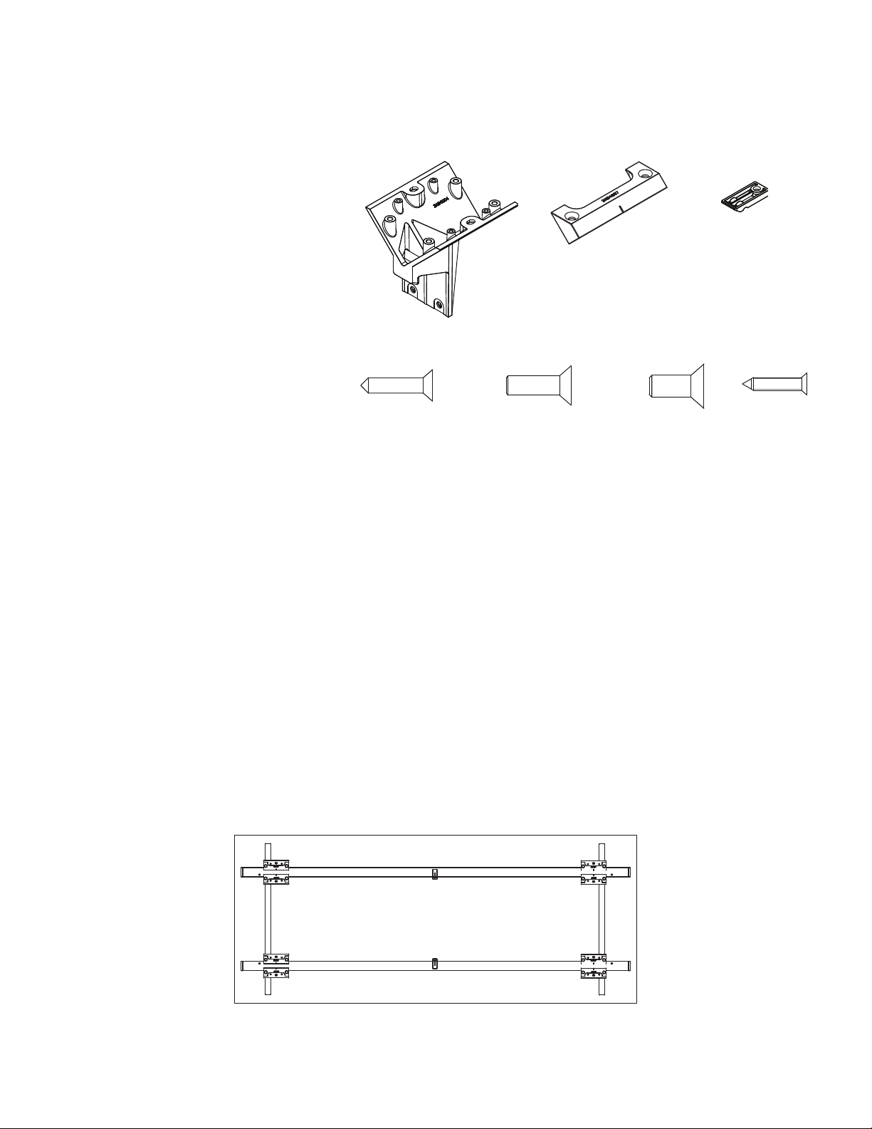
A Graphic Section has been included, to
the right of the Parts List, depicting images of
the component parts with lettered codes that
correspond to those in the Parts List. Each part
is shown with its associated part number above.
NOTE: Part numbers with an asterisk, i.e. *,
after the number require a paint finish code
to be added to the end of the pattern number
to be orderable as a replacement part.
Please refer to the Finish Code listing at the
end of this page for the available codes.
NOTE: Part numbers with empty brackets, i.e. (_),
after the pattern number indicate that a laminate
or veneer finish code must be added to the
end of the pattern number to be orderable as a
replacement part. Please refer to the Finish Code
listing in the Antenna™ Workspaces Price List for
the available finish codes for those products.
Please note that not all parts are available
in all finishes. Finish options available for
component parts match those available when
ordered with the complete items’ pattern number
per the Antenna™ Workspaces Price List.
The Steps section details step-by-step
instructions for the installation of the application
selected. Each step includes references to the
lettered items noted in the Parts List at the
top of the page and in the graphic section.
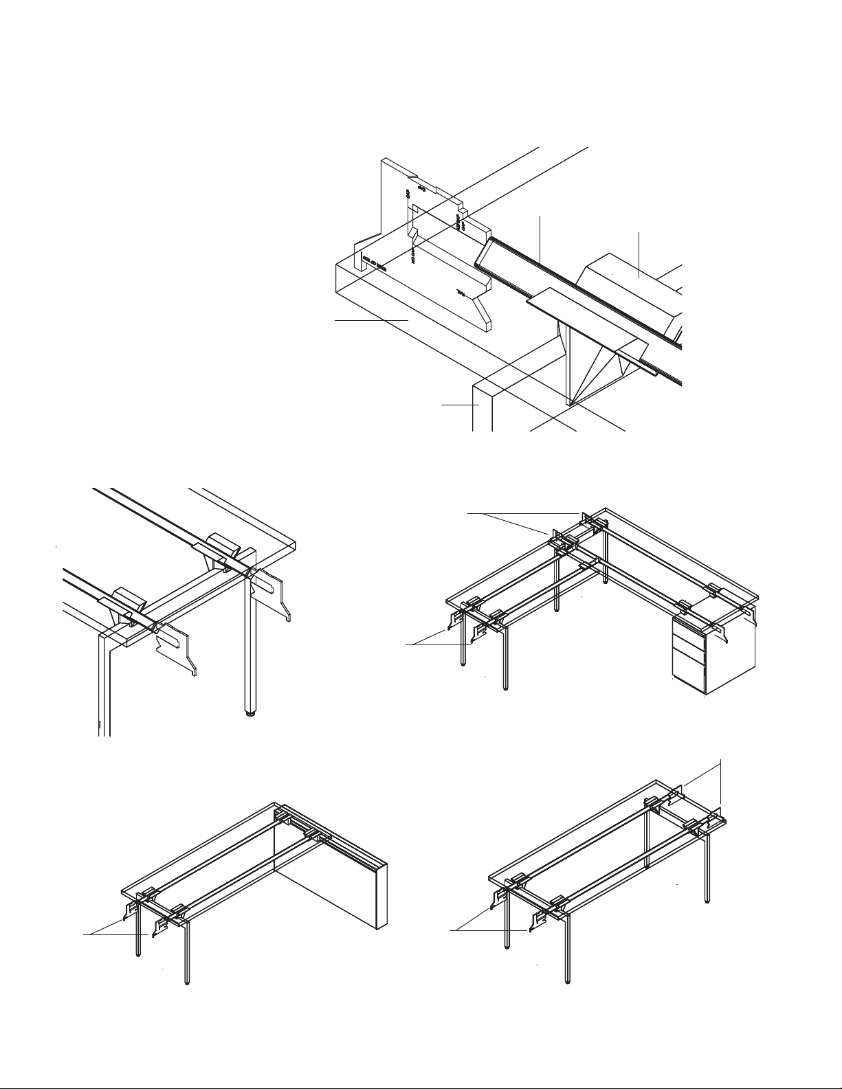
A Drawings section follows the steps section
providing detailed assembled and exploded
drawings to further assist in installation and
in determining replacement parts required.
How to Order Parts
1. Look in this document’s bookmarks to locate
the configuration which best fits the application.
2. Go to the page where that application
is described and thoroughly review all
installation instructions to determine
the part number(s) needed.
3. Unless otherwise noted, the standard package
quantity is one (1). When ordering products
where the quantity per package is listed,
please indicate the number of packages
required in the quantity column of your order.
4. Be sure to add "KR" to the beginning
of each part number.
5. Be sure to include any finish codes required
to complete the pattern number(s).
6. Complete a Knoll Service order,
which can be sent to your Knoll
Customer Service Representative.
If you have any questions about the
contents of this manual, please call
your Customer Service Representative
or Field Service at 800-343-5665.
Paint Finish Codes:
111T - Jet Black
112T - Brown
113T - Dark Grey
114T - Folkstone Grey
115T - Medium Grey
116T - Sandstone
117T - Soft Grey
118T - Bright White
611T - Beige Metallic Mist
612T - Medium Metallic Grey
613T - Silver
130T - Dark Red
131T - Slate Blue
Introduction

Installation Gauge (YBIG- Package Qty of 5)
Pattern Numbers Represented:
Installation Gauge, YBIG
Overview:
The installation gauge is a tool used to help
create accurate, consistent Antenna Workspaces
installations. The tool can be used in four different
ways while installing Antenna Workspaces
desks or big tables. (See following drawings)
Antenna Installation Gauge Showing 4 Applications

Installation Gauge (YBIG- Package Qty of 5)
Application #1:
Used to position tops over rails. Can also be used
to position rail locations over peds, and rails at
Fence brackets, both relative to the top position.
V cutout in guide sits snug to the side of the rail,
while the edge of the top tab aligns with the edge
of the desk top. Only works when the legs are
table desk legs that match the depth of the top
OR desk legs that are 3" smaller than the depth
of the top. The designated distance is 6 5/8" from
the edge of the top to the centerline of the rail.
Typical Application
Position 1 Detail
Rail
Worksurface
Front Edge
Desk with Return
Freestanding Desk Desk to Fence

Installation Gauge (YBIG- Package Qty of 5)
Application #2:
Used to position the leg assembly from the end of
the rail, when the design is to have the leg inset
5 ½" from the end of the desk top. Recessed
part of the guide sits up against the end of a
rail (with or without end cap) and the end of the
guide sits against the outside edge of the cradle.
Can also be used for big tables if there are no
extension tops or extension cabinets. Cannot
be used for legs that are under a "linked" desk
(the shared leg), tables with extension tops or
cabinets, or desk ends where returns or bridges
are located. Will not work with table desk legs.
Desk with Return
Desk to Fence Freestanding Desk
Cradle
Gauge
Gauge
Gauge
Gauge
Gauge
Support Leg
Position 2 Detail
Typical Application

Installation Gauge (YBIG- Package Qty of 5)
Application #3:
Rail end cap is designed to sit proud of the cradle
by approximately 1/16", so that the end of the rail
and leg are 1 ½" from the end of the top. Guide
is used to dimension from the outside of the rail
end cap to the outside edge of the cradle. Must
be used when the leg is placed at 1 ½" from
the edge of the top, such as when a bridge or
return is to be used to ensure the right location
for the return/bridge rails. Will also locate the
outside edge of the rail and spacer in the Fence
end support bracket (YBAFE25 & YBAFE28).
Position 3 Detail
Typical Application
Desk with Return
Desk to Fence
Cradle
Worksurface
Edge Support Leg
Gauge
Gauge
Rail

Installation Gauge (YBIG- Package Qty of 5)
Application #4:
Used to position the leg assembly from the
end of the rail, when the design is to have the
leg inset 5 ½" from the end of the desk top.
Desk with Return
Freestanding Desk
Position 4 Detail
Typical Application
Cradle
Gauge
Gauge
Gauge
Gauge
Gauge
Worksurface
Edge
Support Leg
Rail
Desk to Fence

STEPS:
1. Attach desk cradles (A) to legs, (2) per leg, using
(2) ¼-20 x 1" machine screws (E) per cradle (A).
2. Attach (1) pair of horizontal rails to cradles
(A) by first fastening (2) cradle clamp
brackets (B) loosely to each cradle (A)
using (4) ¼-20 x 5/8" machine screws (F).
NOTE: Rails are typically 3" shorter than top
width. ie: 72" wide tops use 69" wide rails.
Install (4) end caps into the ends of the rails
using the rubber mallet. Slide one end of each
rail into the cradle/clamp assemblies on one
leg, with rail paint holes facing up and toward
the center of the table desk assembly.
NOTE: If a glass top is being used,
holes are to face down and toward
center of the table desk assembly.
Position the outer edge of each cradle
(A) 4" from the end of the rail. Use gauge
to properly position rails. See Install
Gauge Guidelines. Tighten the screws
(F) in the cradle clamp brackets (B).
3. Attach other ends of the rails to the (2) cradles
(A) in the other leg assembly as noted in step 2.
4. If applicable, attach suspended storage,
returns and/or electrical components at this
time. (see suspended storage, table desk with
return and electrical installation instructions)
5. Surfaces 48" wide and greater require a spacer
(C) for additional support. When necessary,
a spacer (C) should be placed between the
top of each rail and the underside of the top,
centered on the width of the top. Spacers
(C) are attached to the top using (1) #12 X
¾" black wood screw (D) per spacer.
6. Lay top on base assembly. Use gauge to
properly position top. See Install Gauge
Guidelines. Attach top using (2) #14 x 1" FH
wood screws (G) per cradle (A) into pre-
drilled holes in the underside of the top.
7. Adjust glides as needed to level desk.
3AB4004
Desk (Inset Legs)
Pattern Numbers Represented:
Legs for Desks or Returns
(Desk or Standing Height), YEL__
Starter Rails with End Caps, YBRS_
Part List:
Horizontal Rail Cradle (A)
Cradle Clamp Bracket (B)
Spacer (C)
#12 X ¾" Black Wood Screw (D)
¼-20 x 1" Machine Screw (E)
¼-20 x 5/8" Machine Screw (F)
#14 x 1" FH Wood Screw (G)
Rails
Desk End Legs
Top
Tools Needed:
Drill
Install Gauge
Phillips #2 and #3 bits
Rubber mallet
7434100
Screw, SM, FLP 14 X 1 Type A CAD or Zinc
G.) 74 34100F) 7189140D.) 7196440 E.) 7194140
3AB4012
B.) 3AB4007*A.) 3AB4004* C.) 3AB401252
3AB4040
Screw, Mach, FLP 1/4-20 X 1
Desk Assembly Plan View
Desks and Tables

ANTENNA 06 O
ANTENNA 06 O
Desk (Inset Legs)
Rail
Cradle Clamp
Brackets (B)
Cradle Clamp
Bracket (B)
Horizontal Rail
Cradle (A)
Horizontal Rail
Cradle (A)
Desk End Leg
End
Caps
Desk End Leg
Step 1 & 2
Step 7
Desk Cradle Connection to End Leg Assembly Detail Exploded Table Desk Cradle Connection to End Leg Detail
Exploded Desk Assembly
¼-20 x 5/8"
Machine Screw (F)
#14 x 1" FH
wood screw (G)
¼-20 x 1" Machine Screw (E)

Table Desk (Flush Legs)
Pattern Numbers Represented:
Legs for Table Desks (Desk Height), YELS__
Starter Rails without End Caps, YBRT_
Part List:
Table Desk Cradle (A)
Cradle Clamp Bracket (B)
Spacer (C)
#12 X ¾" Black Wood Screw (D)
¼-20 x 1" Machine Screw (E)
¼-20 x 5/8" Machine Screw (F)
#14 x 1" FH Wood Screw (G)
Rails
Table Desk End Legs
Top
Tools Needed:
Drill
Phillips #2 and #3 bits
STEPS:
1. Attach table desk cradles (A) to
legs, (2) per leg, using (2) ¼-20 x 1"
machine screws (E) per cradle (A).
2. Attach (1) pair of horizontal rails to cradles
(A) by first fastening (2) cradle clamp
brackets (B) loosely to each cradle (A)
using (4) ¼-20 x 5/8" machine screws (F).
NOTE: Rails are 3" shorter than top width.
ie: 72" wide tops use 69" wide rails.
Slide one end of each rail into a cradle/clamp
assembly, with rail paint holes facing up and
toward the center of the table desk assembly.
NOTE: If a glass top is being used,
holes are to face down and toward
center of the table desk assembly.
NOTE: End of rail must be fully inserted
against (not on top of) the "fins" at the
back of the cradle. No endcaps are required.
Tighten the screws (F) in the cradle clamp
brackets (B).
3. Attach other ends of the rails to the (2) cradles
(A) in the other leg assembly as noted in step 2.
4. If applicable, attach suspended storage,
returns and/or electrical components at this
time. (see suspended storage, table desk with
return and electrical installation instructions).
5. Surfaces 48" wide and greater require a spacer
(C) for additional support. When necessary,
a spacer (C) should be placed between the
top of each rail and the underside of the top,
centered on the width of the top. Spacers
(C) are attached to the top using (1) #12 X
¾" black wood screw (D) per spacer.
6. Lay top on base assembly. Attach top using (2)
#14 x 1" FH wood screws (G) per cradle (A) into
pre-drilled holes in the underside of the top.
7. Adjust glides as needed to level table desk.
3AB4069
3AB4012
7434100
Screw, SM, FLP 14 X 1 Type A CAD or Zinc
3AB4040
Screw, Mach, FLP 1/4-20 X 1
A.) 3AB4069* B.) 3AB4007* C.) 3AB401252
G.) 74 34100F.) 7189140E.) 7194140D.) 7196440
ANTENNA 02 F
ANTENNA 02 G
Table Desk Assembly Plan Table Desk Assembly

ANTANNA 02 E
Table Desk (Flush Legs)
Steps 1, 2 and 6
Step 3
Step 7
Step 5
Table Desk End Leg
Cradle Clamp
Brackets (B)
Table Desk Cradle (A)
Exploded Table Desk Assembly Detail
Exploded Table Desk Cradle Connection to End Leg Detail
#14 x 1" FH Wood Screw (G)
¼-20 x 5/8" Machine
Screw (F)
¼-20 x 1" Machine
Screw (E)
#12 X ¾" Black Wood Screw (D)

Desk with Return (Inset Leg on Return)
Pattern Numbers Represented:
Legs for Desks or Returns
(Desk or Standing Height), YEL__
Return Rails for Desk, YBRR_
Part List:
Horizontal Rail Cradle (A)
Cradle Clamp Bracket (B)
Spacer (C)
Return Rail Hook Top Bracket (D)
Return Rail Clamp Bottom Bracket (E)
W-Bracket (F)
#12 X ¾" Black Wood Screw (G)
¼-20 x 1" Machine Screw (H)
¼-20 x 5/8" Machine Screw (I)
#14 x 1" FH Wood Screw (J)
Rails
End Caps
Desk End Leg
Return Top
Tools Needed:
Drill
Install Gauge
Phillips #2 and #3 bits
Rubber mallet
STEPS:
1. Build table desk assembly (see table
desk assembly instructions).
NOTE: that the Horizontal Rail Cradles (A)
at the end of the desk receiving a return
must be repositioned so they are
at the end of the desk rails.
2. Attach (2) cradles (A) to desk end leg using (2)
¼-20 x 1" machine screws (H) per cradle (A).
3. Attach 1 return rail (YBRR_ _) to each
cradle (A) by first fastening 2 cradle clamp
brackets (B) loosely to each cradle using
(4) ¼-20 x 5/8" machine screws (I).
NOTE: Return rails are 3" longer than the return
top width when connected to a 24"d main top.
Return rails are 6" longer than the return top
width when connected to a 27"d main top.
Return rails are 9" longer than the return top
width when connected to a 30"d main top.
NOTE: Rails are an ADDITIONAL 12"
long when return is connected to an
extension top or cabinet on free end.
For both rails, slide rail into cradle/clamp
assembly with rail paint holes facing up and
toward center of table desk assembly. Use
install gauge to locate the leg position on the
rail. See Install Gauge Guidelines. Tighten the
screws (I) in the cradle clamp brackets (B).
4. Insert (1) end cap onto each
rail with rubber mallet.
5. Install return rail hook top brackets
(D) to other end of each return rail.
6. Attach return rail hook top brackets (D)
perpendicular to and on top of main table
desk rail. Attach a return rail clamp bottom
bracket (E) with (1) ¼ -20 X 1" machine screw
(H) to each return rail hook top bracket (D).
NOTE: The horizontal rail cradles (A) at
the end of a desk receiving a return may
need to be repositioned; The outside
edge of the cradles (A) must be flush with
the end of the desk rails. This repositioning
is unnecessary for table desk cradles as they
are already positioned at the end of the rails.
NOTE: Main table desk top may need to
be loosened to allow clamp to be installed.
7. If applicable, add suspended storage
units at this time. (see suspended
storage installation instructions)
8. Position a W-bracket (F) on each return rail
halfway under the main table desk top.
9. Surfaces 48" wide and greater require a spacer
(C) for additional support. When necessary, a
spacer (C) should be placed between the top
of each rail and the underside of the return
top, centered on the width of the return top.
Spacers (C) are attached to the return top using
(1) #12 X ¾" black wood screw (G) per spacer.
10. Lay return top on return rail/leg assembly. Use
gauge to properly position top. See Install
Gauge Guidelines. Attach return top using (2)
#14 x 1" FH wood screws (J) per cradle into pre-
drilled holes in the underside of the return top.
11. Secure main table desk top and return top
to return rail W-brackets (F), using (4) #14
x 1" FH wood screws (J) per W-bracket.
12. Adjust glides as needed to level return.
3AB4012
3AB4008
3AB4009
3AB4011
7434100
Screw, SM, FLP 14 X 1 Type A CAD or Zinc
3AB4040
Screw, Mach, FLP 1/4-20 X 1
A.) 3AB4004* B.) 3AB4007* C.) 3AB401252
D.) 3AB4008* E.) 3AB4009* F.) 3AB4095*
J.) 743 410 0I.) 7189140H.) 7194140G.) 7196440
3AB4004

Desk with Return (Inset Leg on Return)
Return Rail Clamp
Bottom Bracket (E) Return Rail
Hook Top
Bracket (D)
W-Bracket (F)
Return Rail
Desk
Assembly
Return
Assembly
Desk
End Leg
Exploded Return Assembly Detail
Desk with Return Plan View Exploded Return Assembly Plan View
Cradle Clamp
Bracket (B)
Horizontal
Rail
Cradle (A)
Steps 2, 3 and 10
Step 12
Step 4
Steps 8 and 11
Steps 5 and 6
Aligned (Use
install gauge to
properly locate.
See Install
Gauge
Guidelines.)
Horizontal
rail cradle on
desk must be
positioned at
end of rail.
¼-20 x 5/8" machine
screw (I)
¼-20 x 1" Machine Screw (H)
#14 x 1" FH Wood Screw (J)
¼-20 x 1" Machine Screw (H)
#14 x 1" FH Wood
Screw (J)

Table Desk with Return (Flush Leg on Return)
Pattern Numbers Represented:
Legs for Table Desks (Desk Height), YELS_ _
Return Rails for Desk, YBRR_
Part List:
Table Desk Cradle (A)
Cradle Clamp Bracket (B)
Spacer (C)
Return Rail Hook Top Bracket (D)
Return Rail Clamp Bottom Bracket (E)
W-Bracket (F)
#12 X ¾" Black Wood Screw (G)
¼-20 x 1" Machine Screw (H)
¼-20 x 5/8" Machine Screw (I)
#14 x 1" FH Wood Screw (J)
Rails
Table Desk End Leg
Return Top
Tools Needed:
Drill
Phillips #2 and #3 bits
Install Gauge
STEPS:
1. Build table desk assemblies (see table
desk assembly instructions).
2. Attach (2) table desk cradles (A) to the
table desk end leg that will be used
under the return top using (2) ¼-20 x 1"
machine screws (H) per cradle (A).
3. Attach 1 return rail (YBRR_ _) to each
cradle (A) by first fastening 2 cradle clamp
brackets (B) loosely to each cradle using
(4) ¼-20 x 5/8" machine screws (I).
NOTE: Return rails are 3" longer than the return
top width when connected to a 24"d main top.
Return rails are 6" longer than the return top
width when connected to a 27"d main top.
Return rails are 9" longer than the return top
width when connected to a 30"d main top.
Slide rail into cradle/clamp assembly
with rail paint holes facing up and toward
center of table desk assembly.
NOTE: End of rail must be fully inserted
against (not on top of) the "fins" at the back
of the cradle. No endcaps are required.
Tighten the screws (I) in cradle
clamp brackets (B).
4. Attach return rail hook top brackets
(D) to other end of each return rail.
5. Locate return rail hook top brackets (D)
perpendicular to and on top of main table
desk rail. Attach a return rail clamp bottom
bracket (E) with (1) ¼ -20 X 1" machine screw
(H) to each return rail hook top bracket
(D). Main table desk top may need to be
loosened to allow clamp to be installed.
6. If applicable, add suspended storage
units at this time. (see suspended
storage installation instructions)
7. Position a W-bracket (F) on each return rail
halfway under the main table desk top.
8. Surfaces 48" wide and greater require a spacer
(C) for additional support. When necessary, a
spacer (C) should be placed between the top
of each rail and the underside of the return
top, centered on the width of the return top.
Spacers (C) are attached to the return top using
(1) #12 X ¾" black wood screw (G) per spacer.
9. Lay return top on return rail/leg assembly. Use
gauge to properly position top. See Install
Gauge Guidelines. Attach return top using (2)
#14 x 1" FH wood screws (J) per cradle into pre-
drilled holes in the underside of the return top.
10. Secure main table desk top and return top
to return rail W-brackets, using (4) #14 x 1"
FH wood screws (J) per W-bracket (F).
11. Adjust glides as needed to level return.
3AB4069
7434100
Screw, SM, FLP 14 X 1 Type A CAD or Zinc
A.) 3AB4069*
D.) 3AB4008*
B.) 3AB4007* C.) 3AB401252
E.) 3AB4009* F.) 3AB4095*
J.) 743 410 0I.) 7189140G.) 7196440
3AB4008
3AB4009
3AB4011
3AB4040
Screw, Mach, FLP 1/4-20 X 1
H.) 7194140
3AB4012

Table Desk with Return (Flush Leg on Return)
ANTENNA 01 C
ANTENNA 01 B
Return Rail Clamp
Bottom Bracket (E)
Return Rail Hook
Top Bracket (D)
W-Bracket (F)
Return Rail
Table Desk Assembly
Return Assembly
Table Desk End Leg
Exploded Return Assembly Detail
Table Desk with Return Plan View
Exploded Return Assembly Plan View
Cradle Clamp Brackets (B)
Table Desk Cradle (A)
Steps 2, 3 and 9
Step 11
Steps 7 and 10
Steps 4 and 5
¼-20 x 5/8" Machine
Screw (I)
¼-20 x 1" Machine
Screw (H)
#14 x 1" FH
Wood Screw (J)
¼-20 x 1" Machine Screw (H)
#14 x 1" FH Wood
Screw (J)

STEPS:
1. Build desk or table desk assemblies (see
desk or table desk assembly instructions).
2. Attach return rail hook top bracket (B)
to both ends of each bridge rail.
3. Locate return rail hook top brackets (B)
perpendicular to and on top of main table
desk rails. Attach a return rail clamp bottom
bracket (C) with (1) ¼-20 x 1" machine screw
(F) to each return rail hook top bracket
(B). Main table desk top may need to be
loosened to allow clamp to be installed.
NOTE: Bridge rail length varies
according to application.
For example: Rail length will be
6" longer than bridge width when
attached to (2) 24"d main tops.
Rail length will be 9" longer than bridge width
when attached to (1) 24"d and (1) 30"d main top.
4. If applicable, add suspended storage
units at this time. (see suspended
storage installation instructions)
5. Place a W-bracket (D) on each
return rail, positioned halfway under
each main table desk top.
6. Surfaces 48" wide and greater require a spacer
(A) for additional support. When necessary, a
spacer (A) should be placed between the top
of each rail and the underside of the bridge
top, centered on the width of the bridge top.
Spacers (A) are attached to the bridge top using
(1) #12 X ¾" black wood screw (E) per spacer.
7. Lay bridge top on bridge rail assembly. Use
gauge to properly position top and adjust
rail position. See Install Gauge Guidelines.
Secure main table desk tops and bridge top
to bridge rail W-brackets (D), using (4) #14
x 1" FH wood screws (G) per W-bracket.
8. Adjust glides as needed to level
completed assembly.
Table Desk or Desk with Bridge
Pattern Numbers Represented:
Bridge Rails, YBRB_
Part List:
Spacer (A)
Return Rail Hook Top Bracket (B)
Return Rail Clamp Bottom Bracket (C)
W-Bracket (D)
#12 X ¾" Black Wood Screw (E)
¼-20 x 1" Machine Screw (F)
#14 x 1" FH Wood Screw (G)
Rails
Bridge Top
Tools Needed:
Drill
Phillips #2 and #3 bits
Install Gauge
7434100
Screw, SM, FLP 14 X 1 Type A CAD or Zinc
G.) 74 34100F.) 719414 0
3AB4012
A.) 3AB401252 B.) 3AB4008* C.) 3AB4009* D.) 3AB4095*
E.) 7196440
3AB4008
3AB4009
3AB4011

ANTENNA 03 H
ANTENNA 03 I
Table Desk or Desk with Bridge
Table Desk
Assembly
Step 6
Steps 5 and 7
Steps 2 and 3
W-Bracket
(D)
W-Bracket
(D)
Bridge
Top
Spacer (A) Bridge
Rail
Return Rail
Hook Top
and Clamp
Bracket (B & C)
Return Rail
Hook Top
and Clamp
Bracket (B & C)
Table Desk
Assembly
Exploded Bridge Assembly Detail
Table Desks with Bridge Plan View
#14 x 1" FH
Wood Screw (G)
¼-20 x 1" Machine
Screw (F)
#12 X ¾" Black
Wood Screw (E)
#14 x 1" FH Wood Screw (G)
#14 x 1" FH
Wood Screw (J)
¼ -20 X 1"
Machine
Screw (H) ¼-20 x 1" Machine
Screw (F)

STEPS:
1. Attach desk cradles (A) to legs, (2) per leg, using
(2) ¼-20 x 1" machine screws (E) per cradle (A).
2. Attach (1) pair of horizontal rails to cradles
(A) by first fastening (2) cradle clamp
brackets (B) loosely to each cradle (A) using
(4) ¼-20 x 5/8" machine screws (F). NOTE:
Rails are 12" longer than top width for extension
applications. ie: 72" wide tops use 84" wide
rails. Install (2) standard end caps (I) into the
ends of the rails not receiving an extension
top or cabinet with the rubber mallet. Slide
one end of each rail into the cradle/clamp
assemblies, with rail paint holes facing up and
toward the center of the table desk assembly.
NOTE: If a glass top is being used,
holes are to face down and toward
center of the table desk assembly.
Position the outer edge of the cradles (A)
4" from the end of the rail on the side of the
assembly that is not to be extended. For the
side that is to be extended, the outer edge of
the cradles (A) should be inset 12" from the end
of the rails. Use gauge to help properly position
legs. See Install Gauge Guidelines. Tighten the
screws (F) in the cradle clamp brackets (B).
3. Attach other ends of the rails to the (2) cradles
(A) in the other leg assembly as noted in step 2.
4. If applicable, attach suspended storage,
returns, and/or electrical components at this
time. (see suspended storage, table desk with
return and electrical installation instructions).
5. Surfaces 48" wide and greater require a spacer
(C) for additional support. When necessary,
a spacer (C) should be placed between the
top of each rail and the underside of the top,
centered on the width of the top. Spacers
(C) are attached to the top using (1) #12 X
¾" black wood screw (H) per spacer.
6. Lay top on base assembly. Use gauge to
properly position top. See Install Gauge
Guidelines. Attach top using (2) #14 x 1"
FH wood screws (G) per cradle (A) into
predrilled holes in the underside of the top.
7. Secure main table desk top and extension top
or cabinet using W-brackets (D) and tabbed end
caps (J) included in connector kit YBCDE. Use
(4) #14 x 1" FH wood screws (G) per W-bracket,
and (1) #14 x 1" FH wood screw per end cap.
7a. For extension top applications, attach
15" wide extension top using (4) #14 x
1" FH wood screws (G) per W-bracket.
Extended rail should be 4 ½" inset from
the outer edge of the extension top.
7b. For above desk extension cabinet applications,
place cabinet on top of rails with (4) #14
x 1" FH wood screws (G) per W-bracket.
Extended rail should be 4 ½" inset from
the outer edge of the extension cabinet.
7c. For below desk extension cabinet applications,
slide cabinet on rails and attach with (4) #14 x
1" FH wood screws (G) per W-bracket. The top
of this cabinet should be on an even plane with
the main top. Extended rail should be 4 ½" inset
from the outer edge of the extension cabinet.
8. Adjust glides as needed to level desk assembly.
OPTIONAL STEP FOR FABRIC INSERTS:
9. Remove paper backing from double sided
adhesive tape. Place fabric insert in the recess
behind the back of the extension cabinet,
pressing the four corners firmly to attach.
3AB4004
Desk with Extension Top or Cabinet (With Legs Under Worksurface)
Pattern Numbers Represented:
Connector Kit for Desk Extension Tops, YBCDE
Connector Kit for Above or Below Desk
Extension Cabinets, YBCDE
Legs for Desks or Returns (Desk or Standing Height), YEL__
Starter Rails with End Caps, YBRS_
Fabric Inserts for Above Desk Extension Cabinets, YSDXFB_
Part List:
Horizontal Rail Cradle (A)
Cradle Clamp Bracket (B)
Spacer (C)
W-Bracket (D)
¼-20 x 1" Machine Screw (E)
¼-20 x 5/8" Machine Screw (F)
#14 x 1" FH Wood Screw (G)
#12 X ¾" Black Wood Screw (H)
Standard End Cap (I)
End Cap with Support Tab (J)
Rails
Desk End Legs
Top
Fabric Inserts
Tools Needed:
Drill
Install Gauge
Phillips #2 and #3 bits
Rubber Mallet
7434100
Screw, SM, FLP 14 X 1 Type A CAD or Zinc
G.) 74 34100
3AB4012
B.) 3AB4007*A.) 3AB4004*
D.) 3AB4095*
C.) 3AB401252
E.) 7194140
I.) 3AB4000*
F.) 7189140
J.) 3AB4014*
H.) 7196440
3AB4040
Screw, Mach, FLP 1/4-20 X 1
3AB4011
Table of contents
Popular Office Equipment manuals by other brands

Pauli + Sohn
Pauli + Sohn EVERYSPACE installation instructions

Jason.L
Jason.L Sapphire Meeting Table Assembly instructions

BENE
BENE NOOXS THINK TANK Assembly instructions

Topaz Systems
Topaz Systems SignatureGem T-S261-HSB user guide

Ricoh
Ricoh Aficio MP 9000 operating instructions

Spectrum Industries
Spectrum Industries Inspiration Keyboard Tray Assembly instructions